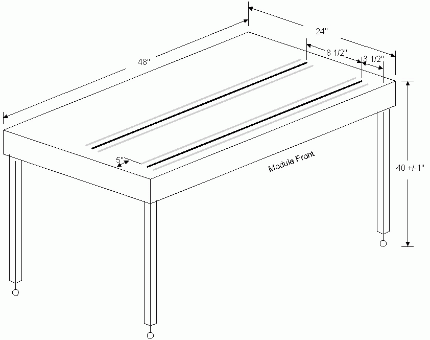
Basic module size is 24" x 48". Optional widths are 30" and 36"; optional
lengths in multiples of 48" although other lengths are permissible if two modules
of the same length are supplied.
Height from floor to railhead is 40" with legs adjustable plus or minus one inch.
Track should be Lionel O-Gauge tinplate tubular (or equal) in new condition.
Each module has at least two main lines, the first line has the center rail 3 1/2"
from the front of the module. the second line is 8 1/2" off center from the first.
Mainline tracks end 5" from each end of the module. Each operator is to supply
two connecting 10" sections (called bridge tracks), one for each main line, all
of O-gauge straight track.
Each module should have an electrical bus running its length consisting of four
wires no smaller than 16-gauge, preferable 14-gauge. It is recommended that the
wire be soldered as follows: 1 = white for the front main, 2 = red for the
second main, 3 = black for common, and 4 = orange for fixed voltage. Each main
line on the module should be connected to the bus around the middle of the
module. (Note prefabricated wiring harnesses are available from the club at a modest cost).
Modules electrically connect to each other by a female socket (TRW Cinch S304AB)
at each end of the rear of the module, with a separate bridge cable having a male
plug at end end (TRW Cinch P304-CCT). The bridge cable should be a minimum of
24". An alternative is two pigtails on the module, one ending in a male plug
and the other in a female socket. From the inside of the module facing out, the
female socket is to your right following the wise old adage "The Female is Always
Right". An optional 4-pin socket can also be supplied as a convienient
connection for a transformer.
Modules structurally connect by C-clamps. Each operator should supply one
2 1/2" C-clamp for each module.
Each module has a plexi-glass shield along the outside edge that is 4.5 to 6 inches high. This shield is
to prevent equipment from falling onto the floor in case of derailments. It also discourages the public
from touching the trains. The plexi-glass shield is held in place by a piece of base trim board attached
to the module with two bolts and wing nuts. This piece of base trim board also contains a velcro strip to
attach skirts to the module.
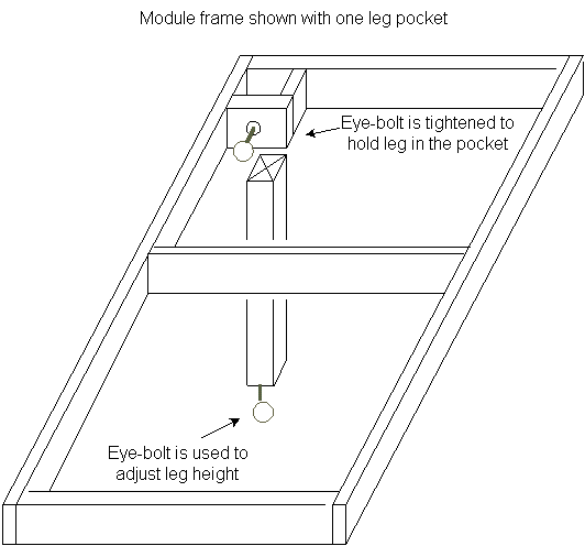
Leg Construction:
Legs can be attached in a number of ways. The simplest and fastest method for set-up
and take-down", is to use "leg pockets". The legs are 1 1/2" x 1 1/2" square and
38" long. A hole is drilled in the center of one end. A 1/4" tee-nut is inserted
into the hole and an eye-bolt screwed into the tee-nut. This is the bottom of the leg.
The eye-bolt can be screwed in and out to adjust the module height.
Pockets are formed in each of the module corners with inside dimensions slightly
larger than the legs. A hole is drilled in one side of each pocket and an eye-bolt
screwed into a tee-nut is inserted into the hole to act as a pin to hold the leg in
place.
The above illustrations were used with the permission of the Crescent Hi-Railers and modified for Tinplate Tracker Standards