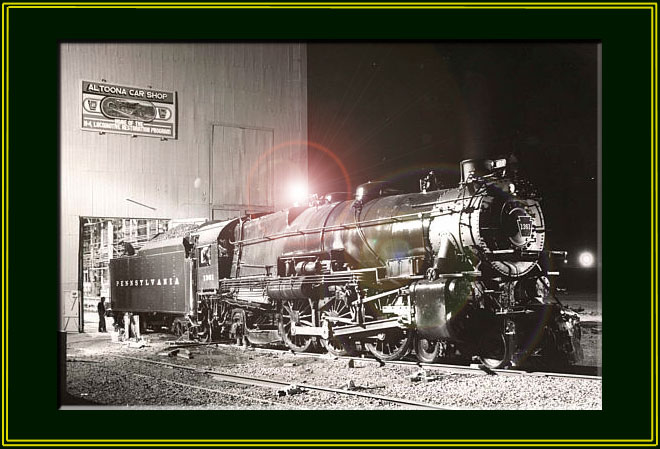
The PRR K-4s #1361
Steam Locomotive Restoration Project
Page 7
(This site is provided as a courtesy of the Altoona Railway Museum Club)
Project Summary (by Brian J. Behe)
The following project summary was composed by Brian J. Behe, who had the opportunity to work full time on the K-4 Restoration project (along with Jeff Miller and several volunteers). The project, from April 2001 through December 2001, is described. Brian also took most of the photographs.
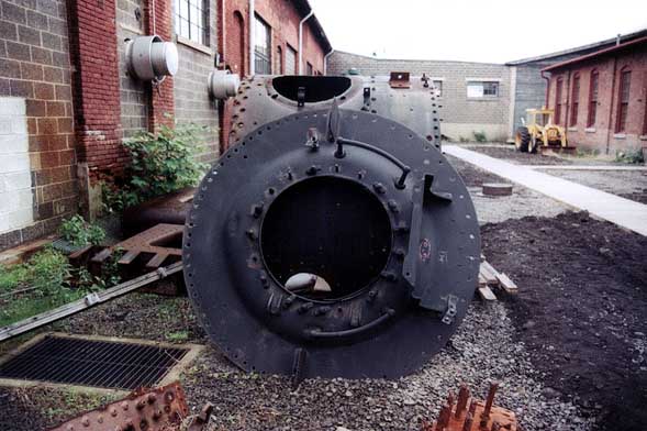 |
Original smokebox with smokebox door. (C. Behe) May 2001 | 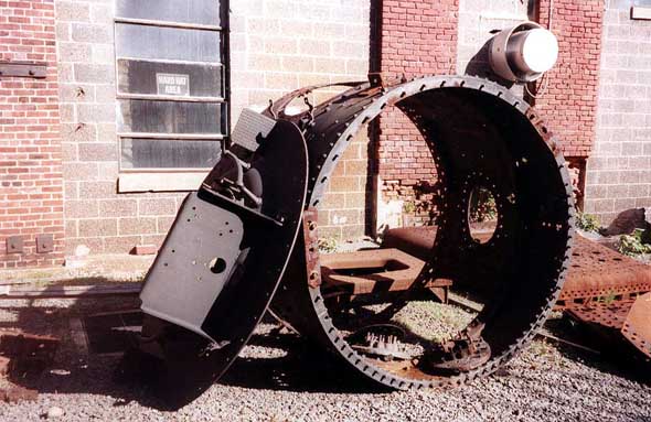 |
Original smokebox with smokebox door, original backhead on ground to the right. |
 |
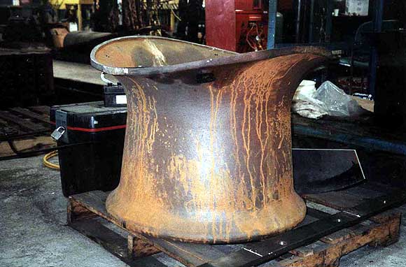
Front- Section of boiler cut out due to cracks. Replaced by patch.
Rear-Original backhead removed due to deterioration |
|
Front- Section of boiler cut out due to cracks. Replaced by patch.
Rear-Original backhead removed due to deterioration |
|
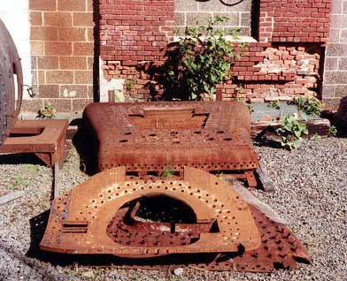
Removed firebox plates with cut stay bolts exposed. |
Washout Flanges
Stud bolts were fabricated and installed onto the two washout flanges located on the belly of the boiler.
The stud bolts were fabricated by first cutting bar stock to length.
The cut bar stock was chamfered on both ends, then the thread was cut onto the bar stock on both ends with an unthreaded section in the middle of the bar stock. (April 16 and 17, 2001) The rear washout flange was riveted into place with the assistance of volunteers Larry Yingling and Stuart Albright. (June 7, 2001)
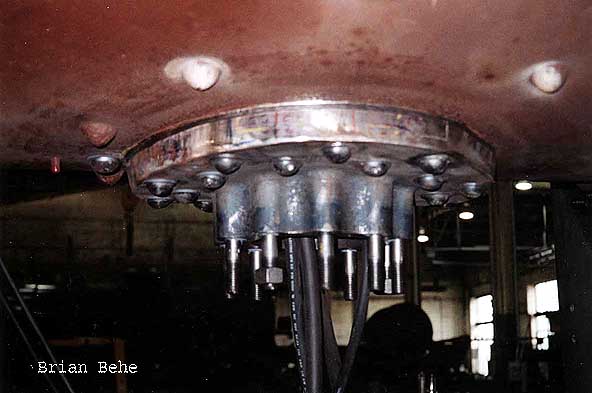 |
Front Washout Flange in belly of boiler | 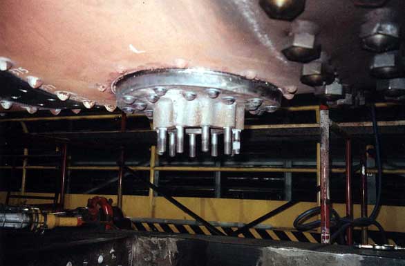 |
Rear washout flange (handhold) without bottom plate. |
Caps for the washout flanges in the belly of the boiler were machined and drilled to fit onto the stud bolts of the flanges. (April 21 and 22, 2001)
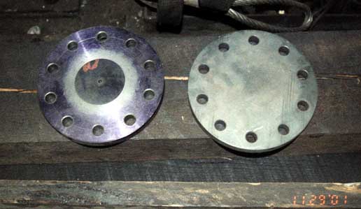 |
Washout Flange caps. (C. Behe) November 2001 | 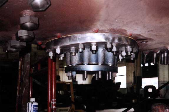 |
Rear washout flange in belly of boiler (with cap loosely fit). |
Smokestack Replacement
Bottom edge of smokestack was ground in preparation for a rough fit on the smokebox. (April 15, 2001)
New smokestack was fabricated due to cracks around bolt holes in original smokestack. (To date, smokestack has not been rough fit on smokebox.)
 |
New smoke stack. | 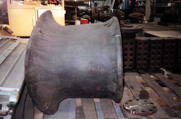 |
Original smokestack laying on its side. Removed due to cracks around bolt holes. |
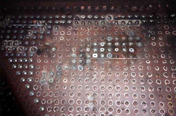
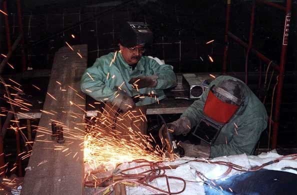
Due to being welded over on the inside of the firebox or being damages due to age, a number of rigid stay bolts and some flexible stay bolts, needed to be replaced.
The process of replacing the stay bolts began with the excess weld being ground off the inside of the firebox on both the left and right sides of the engine.
Once the grinding of all excess was complete, removing the stay bolts to be replaced began.
Removing the rigid stay bolts to be replaced started with grinding the caps off the stay bolts so that the stay bolt is flush with the side sheet of the firebox.
The next step is to burn out the stay bolt with a cutting torch, taking care not to gouge the side sheet. (Volunteer Wayne Laepple assisted in the burning out of the stay bolts.)
The remaining pieces of stay bolt are then knocked free of the hole using a hammer and chisel.
 |
Rigid stay bolts being replaced on inside (right) of firebox. | 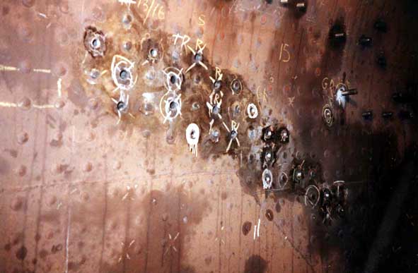 |
Rigid stay bolts being replaced on inside (left) of firebox. |
 |
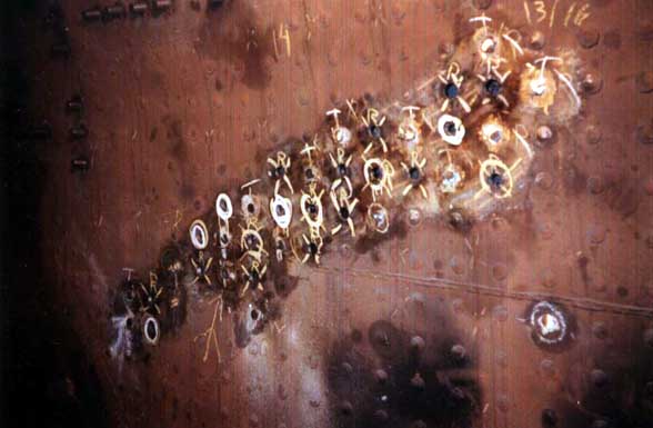
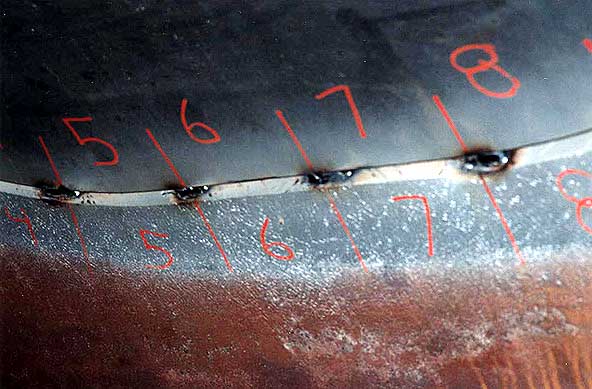
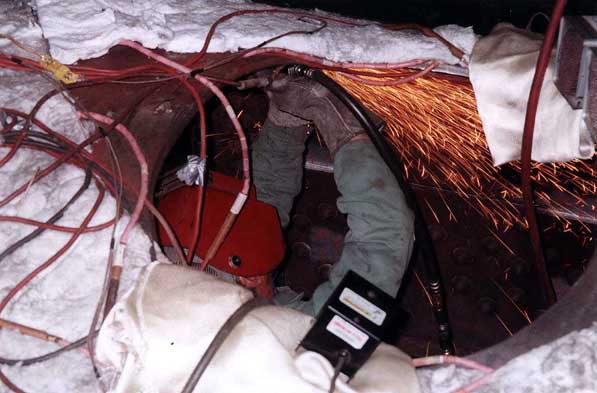
Closeup of rigid stay bolts being replaced on outside (left) of firebox. | 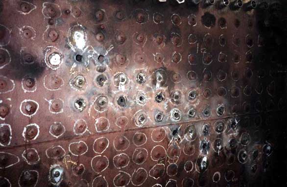 |
Closeup of rigid stay bolts being replaced on outside (right) of firebox. |
After the stay bolts were removed, the original threads in the stay bolt are reamed out using various reamers and an air motor until the hold is smooth. The holes are then welded to reduce the size the hole or to repair a crack in the metal, if necessary. Once welded, the weld is ground down flush with the sheet. The holes are then reamed out to a slightly smaller diameter than the replacement stay bolts.
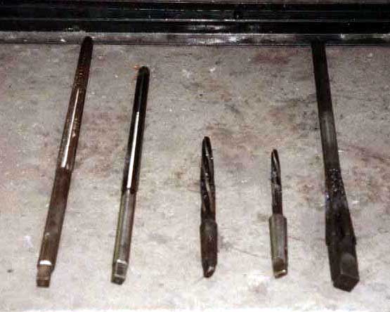 |
Reamers used for rigid stay bolt holes. | Air motor used for reaming holes. |
The stay bolt holes, once reamed out, are tapped out to the diameter of the replacement stay bolt. (Volunteer Wayne Laepple assisted in tapping out the holes.)
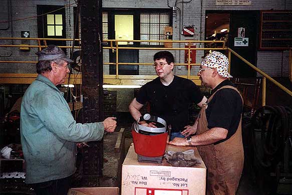
After the stay bolt holes are tapped out, the stay bolts are then screwed into place. (Photo 14; Volunteer Jim Ward assisted in making new stay bolts.) The stay bolts are screwed in until ¼ is extending past the side sheet on the outside of the firebox. The excess stay bolt on the inside of the firebox is cut off with a torch then ground down to ¼. (Volunteer Gary Creighton assisted in the grinding off of stay bolts.)
The final step of stay bolt replacement is to use an air hammer and a bucking tool (Photo 15) to hammer the stay bolts down to 1/8 . If hammering flexible stay bolts, a collar with a piston fits onto the flexible stay bolt sleeve to prevent the weld holding the sleeve from cracking. (Volunteers Gary Creighton, Walter Elridge, Tim Barney, and Adam Counterman assisted in hammering stay bolts.)
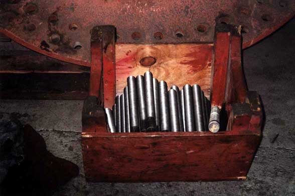 |
Photo 14. Box of rigid stay bolts for firebox. |  |
"Bucking" tool for hammering stay bolts after installation. |
 |
Left side (inside) of firebox - completed stay bolt replacement. |  |
Left side (outside) of firebox - completed rigid and flexible stay bolt replacement. |
Boiler Patch Project (May 14 June 8, 2001)
 |
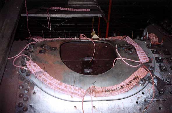
Boiler in area of Steamdome, Prior to being patched. May 2001. (C. Behe) |
Due to the discovery of cracks between the rivet holes on the boiler when the steam dome was removed (date unknown), it was determined to replace the cracked section of boiler with a six-by-six patch of one inch thick steel.
 |
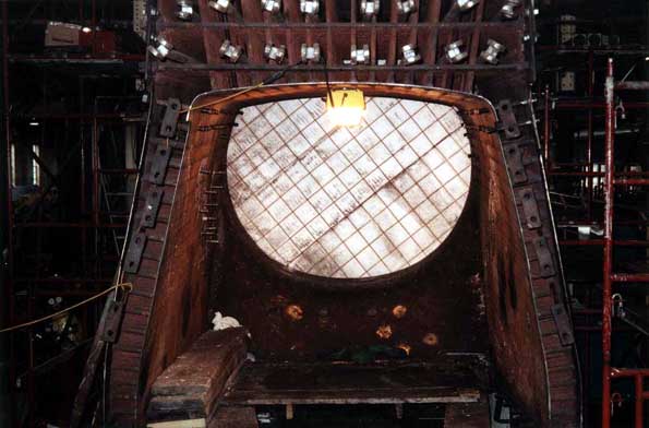
Ceramic heating pads to heat patch to 200 degrees F. Placed along inside and outside of the grove. 5/14/01 |  |
Top of Firebox. Ceramic heating pads in the foreground. 5/14/01 |
Inside the boiler, a platform was erected to provide a surface for the welders to work from.
A spider, or x-shaped brace, was installed to control the distortion of the steel caused by the heat of the welding process.
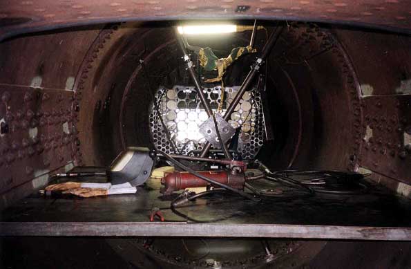 |
Platform set up inside the boiler for the boiler patch welding project. 5/14/01. |
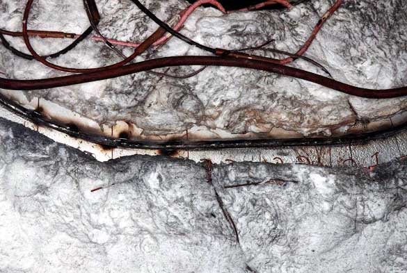
After heating the area to be welded, the next step was to tack weld the patch into place. This tack weld was placed every six inches.
 |
Boiler patch - ceramic heating pads covered by insulation (tack welded) 5/14/01 | 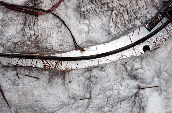 |
Boiler patch - (close up) tack welded (outside boiler) 5/14/01 |
 |
Boiler Patch tack welded every six inches (inside boiler). 5/15/01 | 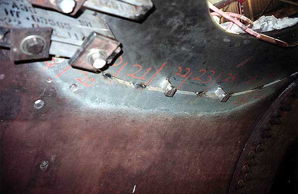 |
Boiler Patch tack welded every six inches (inside boiler). 5/15/01 |
 |
Welding Contractors Bill Frederickson (L) and John Scondras (R) discussing welding of boiler patch. 5/17/01 |
 |
Boiler patch (close up) after first pass. 5/15/01 |
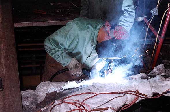
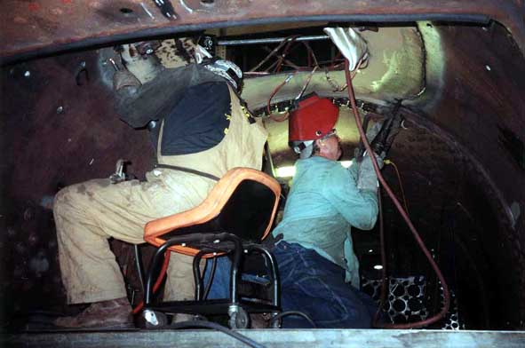
A second pass was then welded with a welder inside the boiler and a welder outside the boiler welding the same section at the same time.
This second pass, and remaining passes of weld followed the same weld, peen, grind, brush procedure described above.
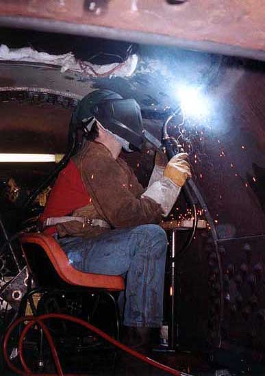 |
Jeff Miller welding on inside of boiler patch. 5/16/01. | 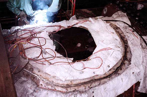 |
John Scondras welding on outside of boiler. Jeff Miller welding on inside of boiler patch. Second Pass. 5/16/01. |
 |
John Scondras welding on outside of boiler. | 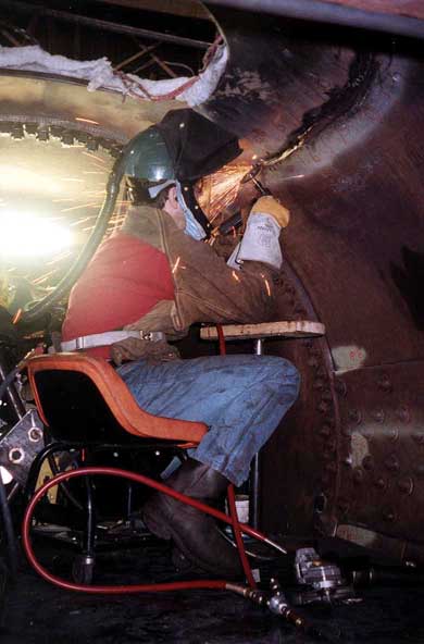 |
Jeff Miller grinding on inside of boiler patch. 5/16/01. |
 |
Bill Frederickson grinding on outside of boiler patch. John Scondras in background. 5/16/01. | 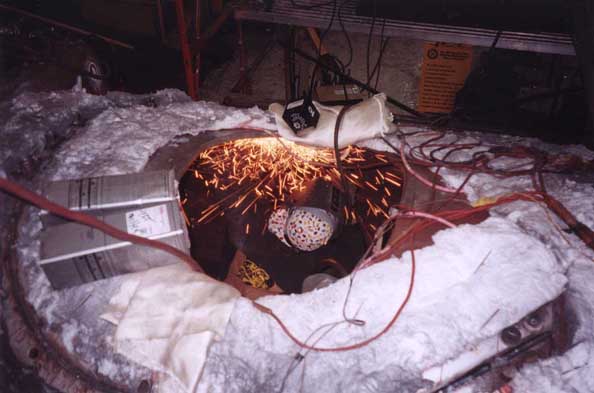 |
John Scondras grinding on inside of boiler patch. 5/15/01. |
 |
Bill Frederickson and John Scondras working on inside of boiler. 5/17/01. | 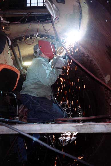 |
Bill Frederickson grinding on inside of boiler patch. 5/17/01. |
 |
Bill Frederickson grinding on inside of boiler patch. 5/15/01. | 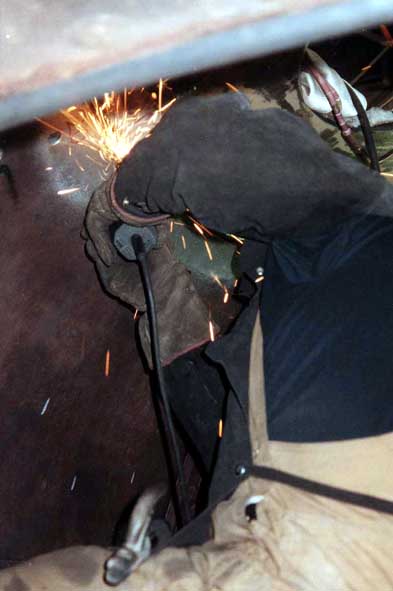 |
John Scondras grinding on inside of boiler patch. 5/17/01. |
After the second pass was complete, the weld was x-rayed to ensure that the weld had no cracks or imperfections.
An imperfection two inches long was discovered.
As a result a two foot section was ground out and re-welded.
A second x-ray was conducted and found no cracks or imperfections.
The welding continued after the x-ray revealed no imperfections. The final pass of weld was again subject to being x-rayed to ensure a good weld. The final pass of weld passed the final x-ray leading to the next step of the project. Using natural gas blowers, the section of boiler with the patch was heated to 1100 ° F to relieve the stress in the steel caused by the welding. The boiler was slowly heated to 1100 ° F, held at 1100 ° F for one hour, then allowed to cool.
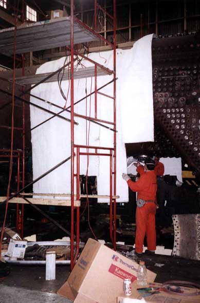 |
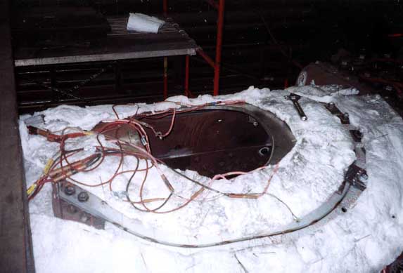
Cooper Heat employees insulating boiler for post weld heat treatment. 5/18/01 | 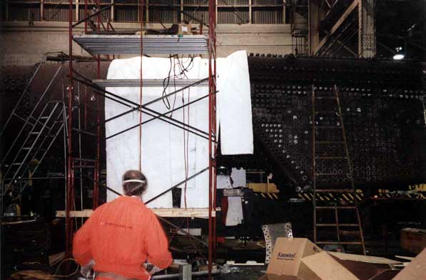 |
Cooper Heat employees insulating boiler for post weld heat treatment. 5/18/01 |
 |
Insulation bulkhead inside boiler (throat of firebox. 5/18/01 | 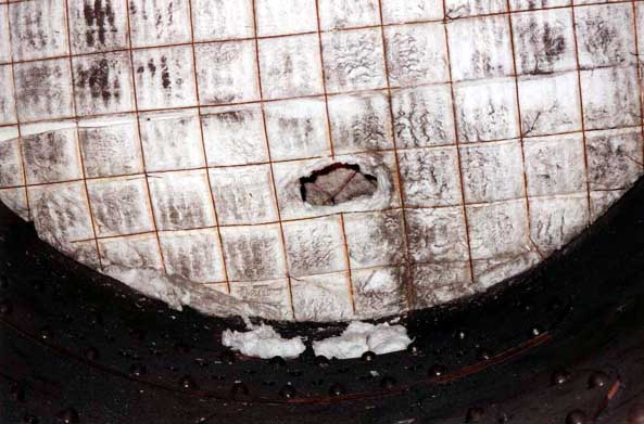 |
Close up. Insulation bulkhead for post weld heat treatment. 5/18/01. |
The final step of the boiler patch project was to apply fault check to the weld to check for cracks.
No cracks were found.
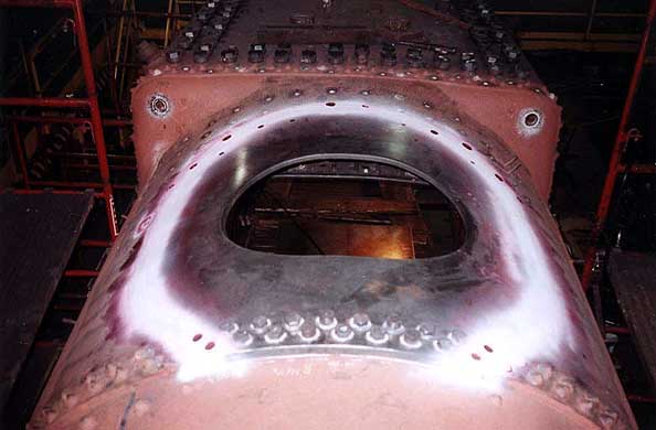 |
Boiler patch (from front of locomotive). 6/8/01 | 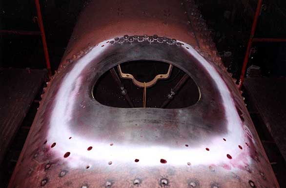 |
Boiler patch (from on top of firebox of locomotive). 6/8/01 |
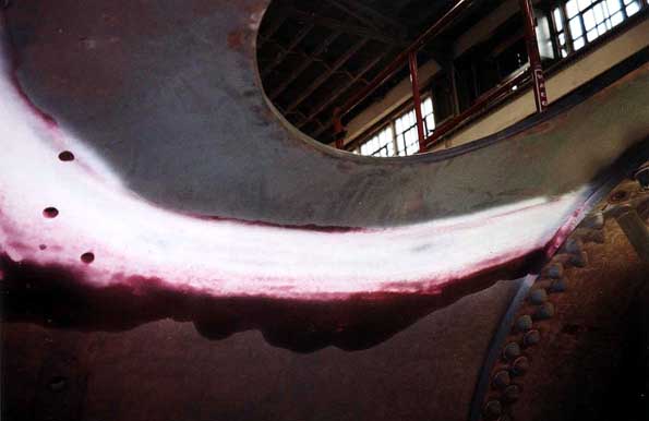 |
Left side of Boiler patch (inside) with fault check. No cracks. 6/8/01 | 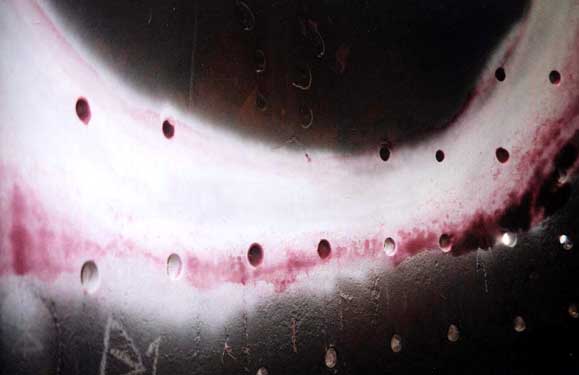 |
Back of boiler patch (inside) with fault check. No cracks. 6/8/01 |
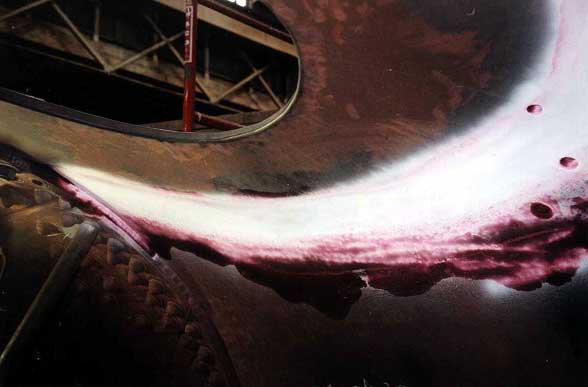 |
Right side of boiler patch (inside) with fault check. No cracks. 6/8/01 | 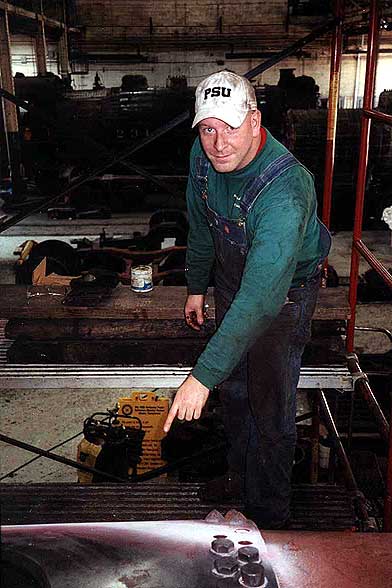 |
Brian J. Behe examining boiler patch. 6/8/01 |
Stay tuned for additional photographs of the PRR K-4s #1361 Restoration!!

(Railfest is a trademark of Railroaders Memorial Museum, Inc.
The logos for the Altoona Railroaders Memorial Museum is a trademark of the Railroaders Memorial Museum, Inc.
Photographs are by Brian J. Behe unless otherwise noted)