 American Flyer Engine Cab Build
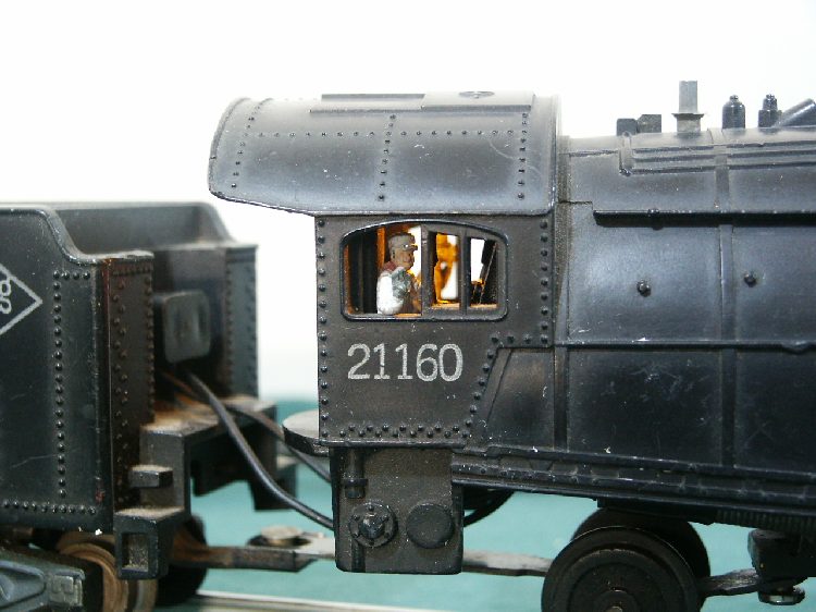
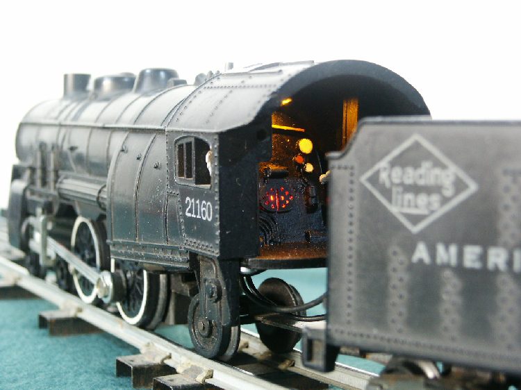
With the open wound motors of the late forties and into the fifties, the need for ventilation was apparent in the engine cab area. The addition of detail in the cab area may have been cost prohibitive so it was left to the imagination of the owner. With a little effort the cab can be created and fits into cavity of the boiler rear with little or no modification to the unit allowing detail to the boiler back and accommodating Arttista figures of engineer and fireman. The prototype can be used for creating a resin mold allowing multiple cab inserts to be created as well hiding the hardware in black resin. I learned that the spacing from the brush housings terminal clips to the rear drawbar anchors have a different spacing based on model design and brush housing used. Also the seat placement is different so I chose to secure them separately based on requirements. Cab uses .031 amps.
This is how I do it.
Materials needed.
|
Qty |
Description |
Where used |
Identification |
|
1 |
.100 thick Sheet ABS plastic |
Boiler back, floor |
|
|
1 |
.050-.060 thick sheet ABS plastic |
Boiler back |
|
|
1 |
.030 thick sheet ABS plastic |
Boiler cover door |
|
|
1 |
.100 plastic dowel/rod |
Gauges |
|
|
1 |
.125 plastic dowel/rod |
Gauges |
|
|
1 |
.075 plastic dowel/rod |
Steam valve |
|
|
1 |
.020-.030 plastic dowel/wire |
Steam pipe |
|
|
1 |
.025x.075 sq plastic rod |
Throttle bar |
|
|
1 |
LED (red) |
Firebox |
754-1255-ND |
|
1 |
LED (amber) |
Overhead Cab light |
LA 3366-R1T2 |
|
1 |
Resistor |
Firebox |
1000 ohm 1/8w |
|
1 |
Resistor |
Cab Light |
330 ohm 1/8 w |
Obtain additional LEDs for the prototype and additional cabs you wish to build as well as resistors
Print copy of boiler and floor plan, cut them out then attach them with white glue to pieces of the .100 thick ABS sheet. When dried, cut out the outline of the parts with scroll saw, or sand/file them to the outline of the drawing. Use drill and file to remove material from the firebox allowing the light to be seen.
Using the boiler back, trace copy onto .050-.060 sheet and cut it out as well. This will be glued to the boiler back allowing the light to be installed in the center of the boiler opening. If you plan on casting future assemblies for your fleet, glue a LED in the hole allowing a recess in the mold to bury the LED on the assembled electronics.
The cab light will also need a base to mount reverse lever and whistle cord. I sanded the terminals from a cab LED and glued it onto a piece of plastic.
Sizes for floor width based on series are as follows: 280 is 1.525”, 290 is 1.600”, 300 is 1.575” (metal) and 1.525” (plastic), 310 is 1.570”, 320 is 1.560”, 330 (unknown for now, 340 is 1.670” and 350 is 1,600”. Once floor is cut for largest of your fleet and back is glued to floor, the width can be sanded to fit.
The boiler back is glued into the floor and leaning toward motor 5/16” from base. This allows max view of the gauges without seeing the back through the windows.
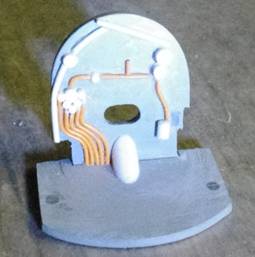
The seats are not secured to the floor at this point. They can be attached via screw through the base or glued to the surface. The seat height also varied by model and if you plan on using figures in the cab, some experimentation may be required to see the figure and get his elbow in the right place. The seat also can’t go all the way back or the insert may not be able to be removed for engine service when it slides back during chassis removal. If making a mold, hot glue during experimentation so seat can be removed and resized and/or repositioned. When you are satisfied with the seat height and position, leave seats on and save for mold making.
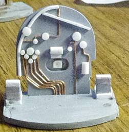
Once the base and back are set, decorate away. I sliced solid rod with miter box and fine saw for gages and used wire art wire for steam and air lines. Allow a gap for the firebox door to extend out from the face allowing the light to show around the cover. You may wish to add the actuation cylinder for the firebox door and a vertical cylinder for the brakes. On one back I added a tube bottom center for coal feeder on heavy pacific(293) or Hudson (322).
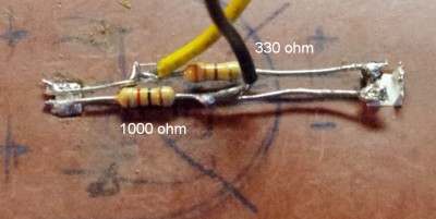
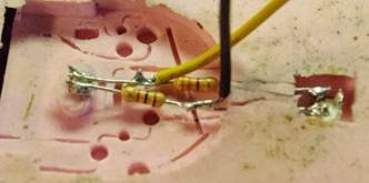
The wiring is assembled off line and installed into the silicone die or epoxy directly to the prototype rear wall facing toward the cab. A template was used to get the LED and resistor spacing right. The wiring is relative to the power to be used. If DC is used, the incoming power should be rectified else the lights will go out when direction is changed if powered with DC. If you have a DC module on board you can wire direct to the light assembly but the wiring may need its own separate supply from the tender. If you are planning to capture power from the motor, the unit will work fine if wired to the Flyer brush terminals. There is not enough draw from the LEDs to affect the motor performance.
The LEDs need to be 1.400” apart or the overhead cab light will extend too far back. I used the wire for the resistors to go between the two LEDs. Attaching the input current to enter above one resistor and below the other allows each of the LEDs to have their own resistor while limiting the input to one incoming wire set (see fig 3). Keep in mind that the firebox light gets the power through the 1000 ohm resistor. If you are using DC power on your track and are changing direction with track polarity, a full bridge rectifier will be required to keep the cab lit during reverse mode. If the lights are too bright after assembly is cast, a resistor can be added to an incoming wire on either wire. I have used up to 1500 ohm on the firebox and 700 ohm on the cab which reduces light emission.
|
|
If you do not plan on casting future assemblies, Paint the prototype assembly with flat or satin black to match your engine. I painted the gauge faces white and faces for the valves red even on the castings using paint pencil found locally. Extreme detail may even involve pictures of gage faces reduced in size, punched out and glued to faces. Where you place your detail may even require cab photos from your nearby railroad museum.
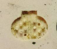
If plans are to create multiples of the cab, create a mold from your prototype that you can pour resin into. The resin does not conduct electricity so the electronics can be buried within the resin casting. Note the mold has the cavity for the firebox door. Casting supplies like box, mold making silicon, and casting resin are available at Amazon. Give your prototype master a quick coat of thin paint with a brush where mold material will go around components like air lines. The silicon will try to pick up the detail, but creates a problem when the resin does not fill correctly and your lines have spots that are missing. Same rules apply for 1/32 holes in door. Note the tabs missing due to complete holes placed in prototype so you may wish to just partially drill holes for mold then drill and saw slots after casting the door.

Above is a cab closely sized at 1.525” width for a plastic Pacific or Atlantic (280 or 300 series). You can increase size with ruler and freehand or a photo editor.
Casting instructions are available on YouTube and materials for casting are on Amazon, Electronics are available At Digikey. and characters are from Arttista.
Below are copies from Train Cyclopedia representing drawn detail of cab interior versions. Happy modeling!