This circuit (by Doug Brown) was taken from the April 1987 issue of "NMRA Bulletin".


Parts List: 1-(1N4001 diode)/1-(220 mf capacitor)/1-(4.7 mf capacitor)/ 2-(0.1 mf capacitors)/1-(1000 ohm resistor)/1-(100,000 ohm resistor)/2-(680 ohm resistors)/1-(LM555 or TLC555)
Two miniture LEDs are needed for this circuit. The clear lens type is preferred for this circuit. The article recommends clear amber 3mm leds.
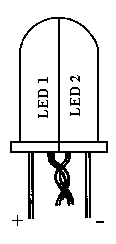
Basically one has to make one led out of two halves of each led. It is necessary to
identify the positive and negative pins on each led. Next decide how you can file each
led in half so that you don't damage the intricate parts (embedded circuit inside each led).
The led is filed parallel to the leads. File leds so that when you put the halves
together, the positive lead of one is adjacent to the negative lead on the other.
File each led so each is a matching half.
Glue these two halves together using a minimum
amount of super glue.
Twist together one positive and one negative lead of each half. These can be soldered but be careful not to damage the leds. These twisted leads will be connected to pin 3 of 555.
At this poit it is necessary to restore the finish to the led unit. Clear nail polish can be used or a clear varnish. This will restore the "clearness" to the leds which had become dull due to filing.
A potentiometer can be substituted for the 100,000 ohm resistor to get the right effect if desired.
The circuit is intended to be run from rail power. If battery power is desired, 330 ohm resistors are substituted for the 680 ohm ones. The 220 mf and 0.1 mf capacitors MAY not be needed in a battery operated circuit. The diode should be left in for battery operation to prevent damage to IC if contacts are reversed.
Addition of 0.1 mf capacitor in parallel with 220 mf capacitor:
As the originator of this particular circuit it was found that (through trial and error) with the addition of this capacitor the circuit would not run "wild". It was dependent on the type of installation- where located within the body cavity, the type and manufacture of the various electric motors, the quality of components used, and what I call a Murphy's Law of a host of other reasons.Since this circuit was first published, white LED's have come on the market. I hope to get some of them and try this circuit out on them.
Doug Brown
Optional Leds or Bulbs can be added - as shown in the circuit.