

The rapid and vigorous motion of the beam from this device causes it to stand out prominently among the numerous stationary or fixed beam lights which tend to compete with each other for attention and contributing to the confusion of the night traveling public.
Major advantages of this light unit are:
1) It is capable of adjustment to produce different motions for a light beam pattern
to suit the requirements of particular railroads or conditions.
2) The unit is weatherproof, while its inner mechanism is easily accessible for
maintenance and repair.
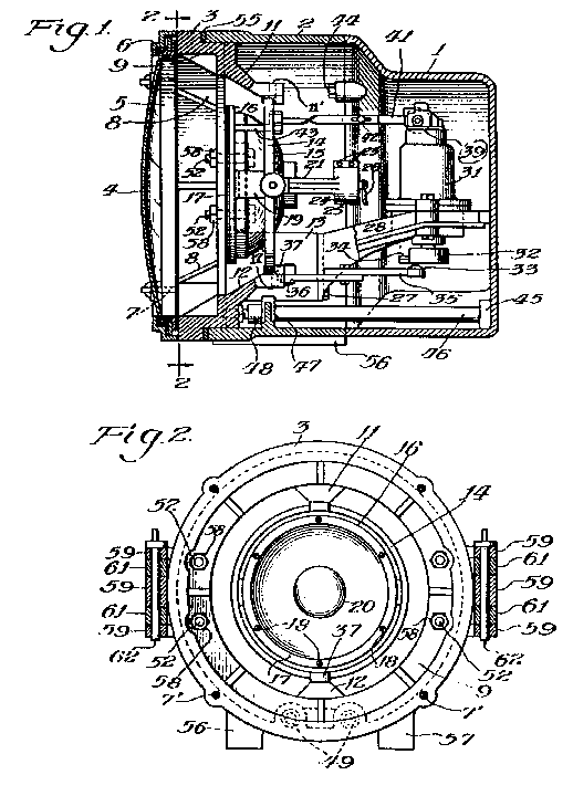
Figure 1 is a longitudinal sectional view with portions in elevation.
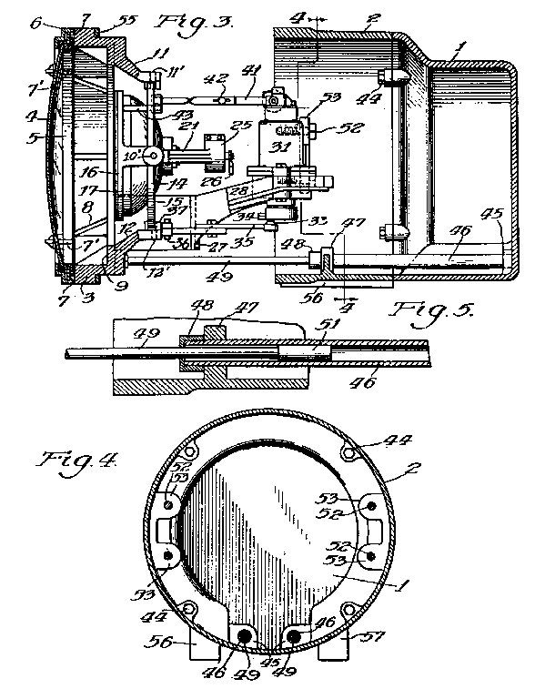
Figure 2 is a sectional view taken on line 2-2 of Figure 1.
Figure 3 is a longitudinal sectional view of the light unit shown in
Figure 1, showing the front section and operating mechanism of the unit ,
partially withdrawn from the casing.
Figure 4 is a sectional view taken on line 4-4 of Figure 3.
Figure 5 is a detail view in section of the sliding support for the
mechanism.
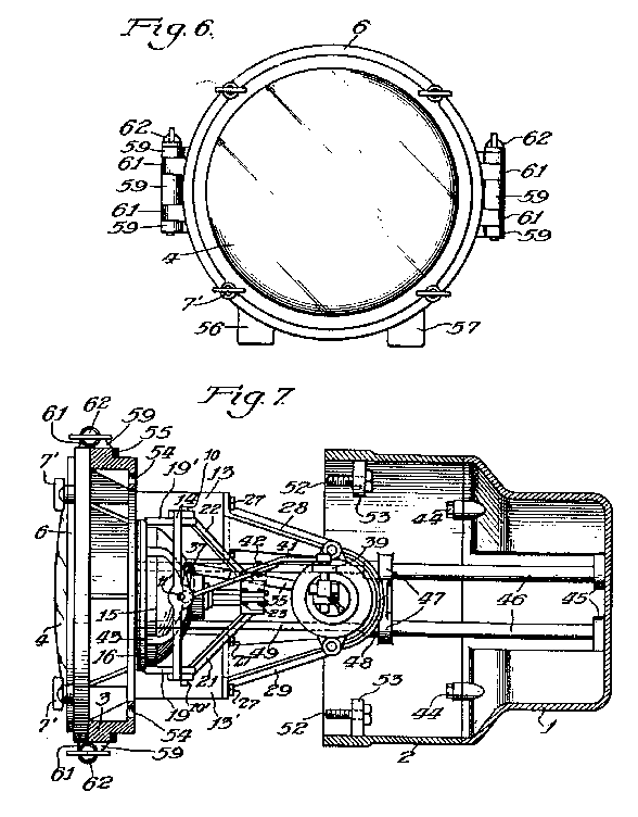
Figure 6 is a front elevation view of Figure1.
Figure 7 is a horizontal sectional view of Figure 1, showing the
operating system in plan view.
The lens 4 preferably has its edges cushioned in a resilient annulus
5 made of rubber or similar material which is firmly fitted in a metal collar
6 and held in by a retaining ring 7.
The annular member 3 is preferably reinforced with a plurality of of radial
ribs such as 8 which extend to the web 9 from which 2 brackets
11 and 12 project rearwardly. The brackets 11 and 12
furnish pivotal support for the reflector 15 or light projecting apparatus.
The reflector 15 is preferably made of the usual thin material, having an inner
reflecting surface. This reflector 15 is secured at its open end to an annular
frame 16. A clamping ring 17 and screws 18 may be used for
this purpose. Extending rearwardly from the frame 16 is a pair of ears on
opposite sides 19 and 19' that are pivotally secured to the
annulus 14 at 10 and 10', and from that point,
extend further rearwardly and inwardly toward each other in the form of arms 21
and 22.
Arms 21 and 22 may be seperate or integral. When seperate, as
shown, they are clamped together by means of bolts such as 23. In this instance
they can grip between their enlarged ends 24 and 25 either the base of
the lamp bulb 20, the bulb socket, or the electrical connections associated with
these.
Supported on the rear ends of the brackets 13 and
13' are a pair of arms 28 and 29, secured by cap
screws 27, to which motor 31 is firmly supported. The shaft of this
motor 31 is vertical and at the lower end of the motor housing is a train of
reduction gears which will reduce the speed of the rotating head 32 to any
desired speed. A ball 33 carried by a slide member 34, which may be
fixed in any desired position of eccentricity relative to the axis of rotation of the head
32, is connected to a pitman rod 35. The forward end of the pitman rod
35 is pivotally connected at 36 to an arm 37 that is integrally
formed with the ring 14.
The reciprocatory motion of the pitman rod 35 which results from its eccentric
position with the rotating head 32, will transmit oscillatory motion to the ring
14. The extent of this oscillatory movement may be varied by varying the
eccentricity of the position of the ball 33. The pitman rod 35 is
composed of 2 sections linked by a bolt (not labeled in figures but referred to as 38).
Adjustment can be accomplished by varying length of the pitman rod 35 via bolt
38. Other forms of adjustable pitman rods may be utilized in this device.
The upper end of the shaft of motor 31 is connected to another train of
reduction gears which drive a head 39. Head 39 is pivotally connected
in an eccentric position to an upper pitman rod 41, which is adjustable in length
at its middle portion 42. The forward end of this pitman rod 41 is
connected to a yoke 43 which is integral with the frame 16. It is
preferable that the axis of the pivotal connection between the yoke 43 and the
pitman rod 41 be in alignment with the pivotal axis of the ring 14 when
the rings 14 and 16 are parallel.
The eccentric connections of the upper pitman rod 41 with the head
39 will produce a tilting of the reflector about the horizontal axis while
reciproction of the lower pitman rod 35 will turn the reflector to the right and left
about a vertical axis.
By varying the amount of eccentricity of the point of connection of each pitman rod to the shaft which drives it, and by varying the lenghts of the pitman rods themselves, the resulting beam of light from this unit can assume different configurations such as arcs, straight lines, and "figure 8's". For most purposes it will be satisfactory to have the light beam assume the "figure 8" configuration. In this pattern, the centers of the 2 loops lie in a horizontal plane and the path of the beam crosses itself at a point directly ahead of the locomotive or other vehicle so equipped. This point may be focused on the track ahead, and by proper adjustments of the pitman rods, caused to strike the track at any desired distance ahead of the locomotive. In addition, the sweep of the beam laterally of the track and upwardly into the air may be varied to suit the different operating requirements on different railroads without unique special designs for such requirements.
Provisions have been made for easy accessibility to the unit's mechanism while
keeping the unit sealed against the weather.
The rear section 1 of the casing is bolted to the intermediate section
2 by a plurality of bolts 44. The rear section 1 is provided at its
rear end with a pair of bosses 45 into which are threaded or secured a pair of
sleeves 46 which extend outwardly until they pass through upstanding brackets
47 which are integral with the bottom of casing 2. The collars
48 serve to lock these sleeves 46 in position and at the same time,
provide a bearing for rods 49 which are connected to pistons 51 which
in turn slide into the sleeves 46. The outer ends of the rods 49 are
secured to frame member 3 in such a way that when frame member 3 is
pulled outwardly, as shown in Figure 3, the entire mechanism for operating the
reflector will be supported slidably on the 2 rods 49. The apparatus when in the
retracted position is securely held by a plurality of stud bolts 52 which are
threaded through the lugs 53 which are integral with the casing 2 and
which pass through the holes 54 that are provided in the web 9 of the
frame 3. A packing ring 55 seals the juncture of the frame and the
casing.
The casing is provided with legs 56 and 58 for mounting.
The lens 4 is preferably hinged to the frame 3 in order to facilitate
access to the nuts 58 on the studs 52. The brackets 59 are
integral with the frame 3. The brackets 61 are integral with the lens
retaining collar 6. These 2 bracket types 59 and 61 are
connected together to form a hinge by hinge pintles 62. By removing 1 of the 2
hinge pintles 62, the lens collar 6 may be swung open to gain access to
the nuts 58. A plurality of bolts 7', screwed into place by
hand, hold the lens collar 6 tightly against the frame 3.