

One important advantage of this invention resides in the provision of a gimbal type movement to the lamp without the necessity of the four or more bearings inherent in the conventional gimbal arrangement. Furthermore, the expense of fabrication and assembly is substantially reduced and maintenance requirements such as lubrication of bearings is virtually eliminated.
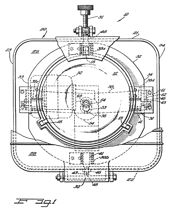
Figure 1 is a front elevational view of the oscillating warning and signal light.
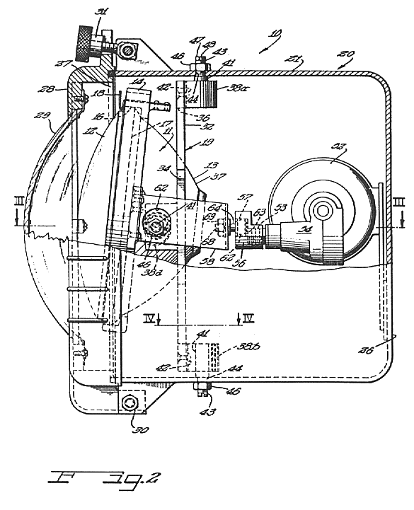
Figure 2 is an elevational side view of the fixture with a portion of the side wall cut
away.
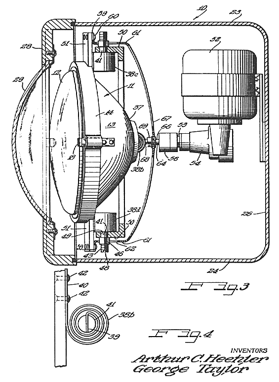
Figure 3 is a horizontal sectional view taken along lines III-III of
Figure 2.
Figure 4 is a top plan view of a helical coil spring assembly taken along lines
IV-IV of Figure 2.
Reference numeral 10 designates generally a moveable or oscillating light fixture for warning and signalling purposes. The fixture 10 comprises an electric lamp 11 which, in the illustrated embodiment, is of the sealed beam type having a lens member 12 mounted over the front of a reflector 13. The lamp unit 11 is removably mounted on an annular lamp holder 14 which is grooved at16 to receive a rim 17 of the lamp unit and includes a plurality of flexible mounting fingers 18 spaced cicumferentially therearound for easy "snap in" assembly of the lamp and lamp holder.
All four of the mounting members 38a-38d are similar and as best illustrated in
Figure 4, comprise respectively a helical coil spring wound about an axis of convolution
from an inner end 39 to an outer end 40. An axially extending cylindrical pin
member 41 is connected in fixed assembly to the inner end 39 of the coil windings.
Springs 38 are connected in fixed assembly to the support member 32
by means of a pair of rivets 42 (or the like) such that the pin members 39 are
coaxially aligned perpendicularly to the top and bottom walls (21 and 22) of the
casing 20. Reduced diameter threaded portions 43 of the pins 41 of
springs 38a and 38b project respectively through aperatures 44
formed in the top and bottom walls (21 and 22), and each receives a threaded
nut 46 for mounting the springs on the walls of the casing and for locking the pin
members 41 agains rotation.
In order to adjust the tautness of the windings of the springs, a radial end wall 47
of each of the pins has formed therein a slot 48 to accomodate a tool such as a screw
driver. Therefore, by loosening the nuts 46, the windings of the springs can be
tightened to substantially negate any unwinding of the springs in an axial direction.
The pins 41 of springs 38c and 38d are aligned axially
transversely to the axis of springs 38a and 38b, and extend respectively
through aligned aperatures 49 formed respectively in a pair of flanges 50
which extend from the flat edges 33 and 34 of the ring-shaped support
member 32 in an axial direction relative to the support member. A pair of threaded nuts
46 are also applied to the threaded portions of the pins for mounting the springs
38c and 38d on the flanges 50, and the outer ends 40 of the
springs are connected in fixed assembly by means of rivets 42 (or the like) to a pair of
radially extending ears 51 formed at diametrically oposite portions of the annular lamp
holder 14.
As a result of the arrangement of the four coiled spring mounting members 38a
and 38d in mounting the support member 32 on casing 20 for pivotal
movement about a first axis while substantially precluding movement of the support member
32 in a direction parallel to said first axis, and in mounting the lamp 11 on the
support member 32 for pivotal movement about a second axis which is transverse to
said first axis while substantially precluding movement of the lamp 11 in direction
parallel to said second axis, the lamp unit is enabled to move in a manner similar to that as
provided by a conventional gimble support structure which includes utilization of a plurality of
bearing assemblies in journalling a pair of concentric rings to each other and a support structure
to enable the smaller ring to pivot about two transverse axes.
In order to move lamp 11 through a fixed path of travel, a motor 52 is
provided within the casing 20 and mounted on the back wall 26 thereof. A
rotatable drive shaft 53 is connected to the shaft of the motor 52 through a
suitable gear mechanism 54 and is threaded to receive a drive coupling 56
having formed therein an axially extending recess 57 situated in radially offset
relation to the axis of drive shaft 53.
A generally "U-shaped" bracket 58 having a pair of outturned flanges 59
is securely fastened to the flanges 51 of the lamp holder 14 by means of
suitable fasteners 60 and comprises a pair of legs 61, each of which is
apertured as at 62 to receive the pins 41 of the springs 38c and
38d and to afford freedom of movement of the pins.
The bracket 58 is drivingly connected to the coupling 56 of the motor
52 by means of a ball and socket arrangement comprising a ball head 62
which is received in a bearing member 63 slidably carried in the recess 57 and
which has extending therefrom, a shank 64. projecting through an aperature 66
formed in a back plate 67 of the bracket 58. An end 68 of the shank
64 is threaded to receive a nut 69 in order to connect the shank in fixed
assembly to the bracket 58.