Note: This page is under construction. Not all components have been marked,
and those that have may be marked incorectly. For the most, markings correspond
to how the equipment was marked on the car. Photos may also be from different
cars.
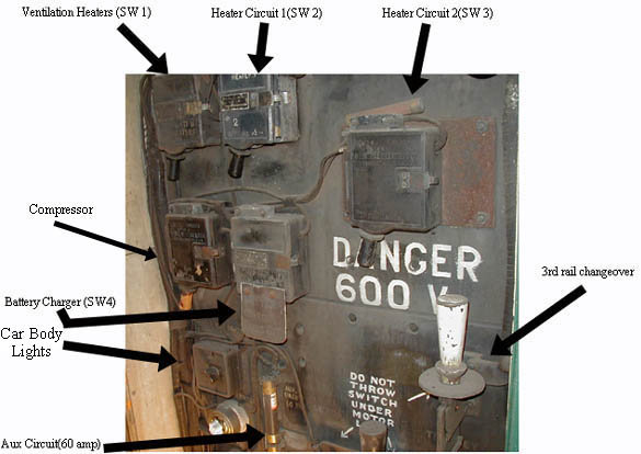
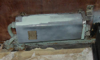
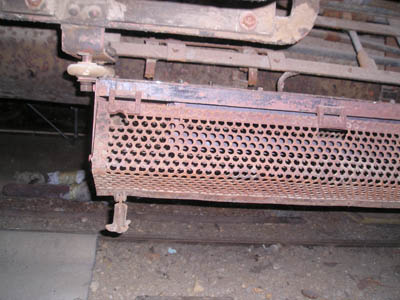
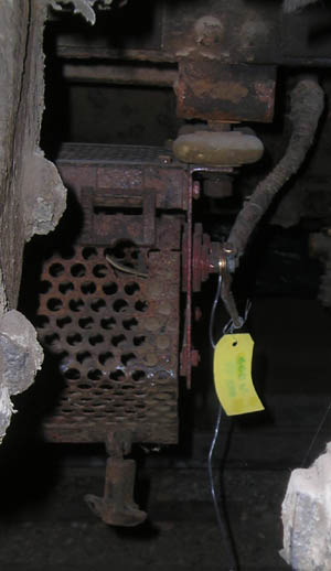
Above: Main fuse cabinet for cars 749-763
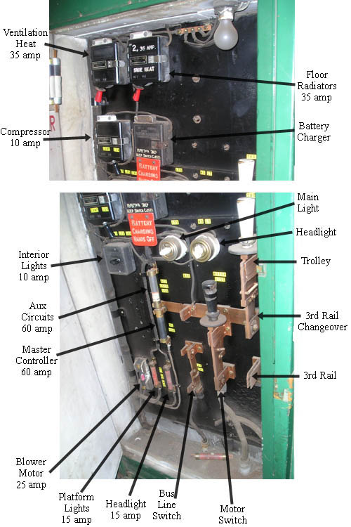
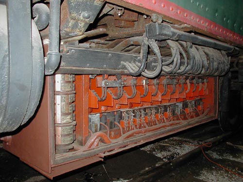
Above: Main fuse cabinet for cars 714-727
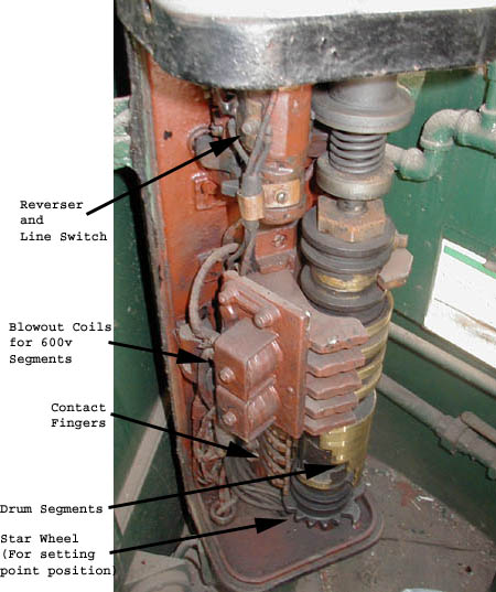
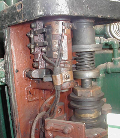
Above: Inside of controller
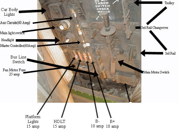
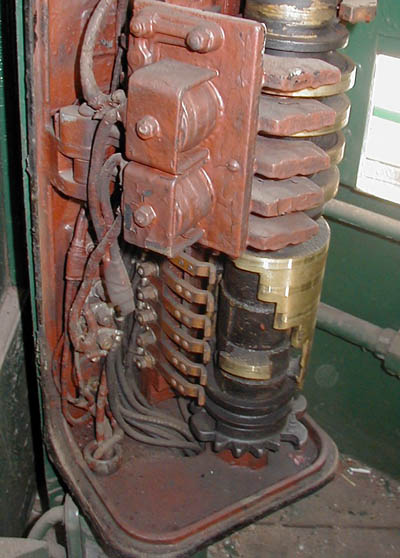
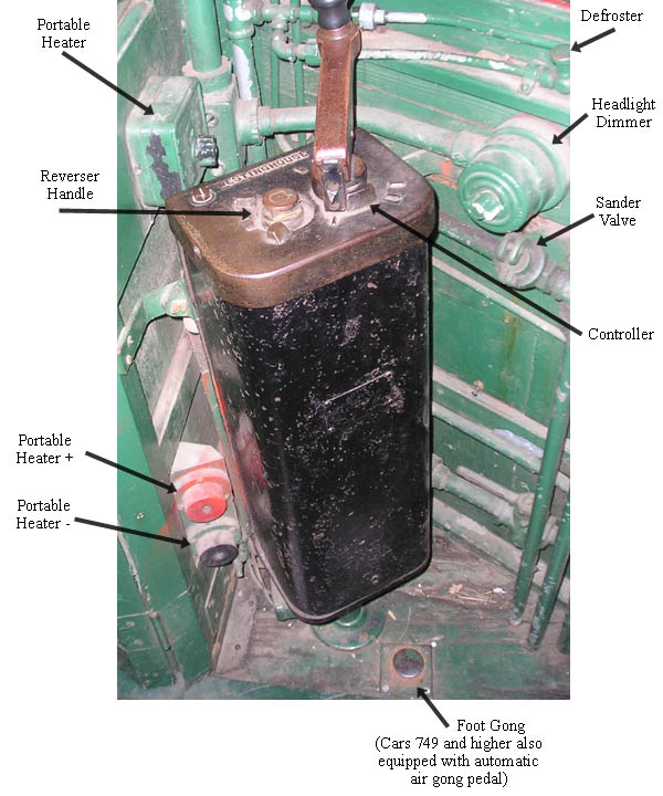
Above: Outside of controller
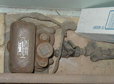
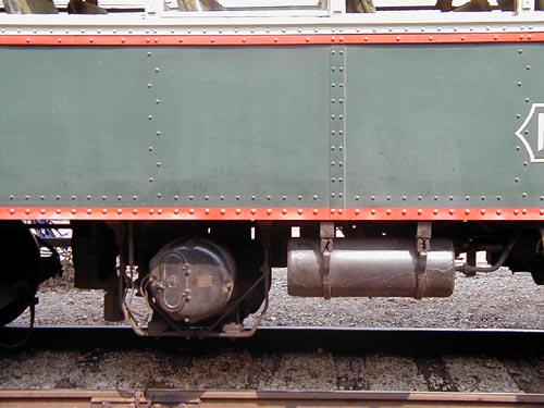
Above: Compressor Governor/Switch
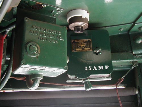
Above: Control Cutout Switch
Above: Under-car Switch Group, motor cut-out cylinder on left, power relays at right.
Above: Compressor(GE, as used on older cars, 160,251
Above: Ceiling of cab, Cab heater switch on left, controller breaker and reset on right.
White Switch is to switch between platform lights and signbox lights. Red box at left
contains 10amp fuse for cab heater
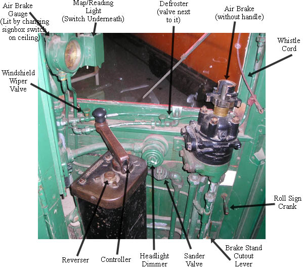
Above: Cab Layout Diagrams (Note: Reverser, brake, and sander handles not inserted)
Portable heater switch contains 10amp fuse for heater
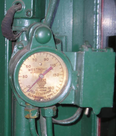
Above: Air Brake Gauge in Cab
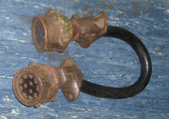
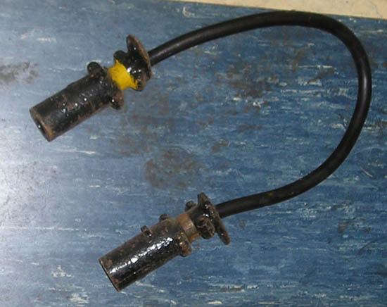
Above: A control circuit jumper for between cars
Above: An 600v electrical bus jumper for trailers without poles
(note: the north shore had several coach trailers as well as diner/tavern and observation trailers)
Below: Heating elements in main car heaters along the floor.
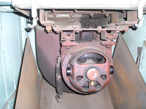
Below: The blower motor for the forced air heating/ventilation.
Black Caps are brush holders, gold cap in middle is one of the grease cups.
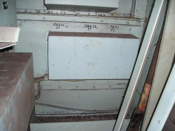
Below: The box with the thermostat resistors/controls in it. Markings indicate
35 and 55 degree overhead heat, and 70 degree floor heat. The box just above
is the air intake, in the steel window plate.
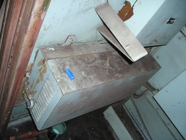
Below: The cases with the heat control relays in them. The bracket on the wall
supports the case around the blower when it is open.
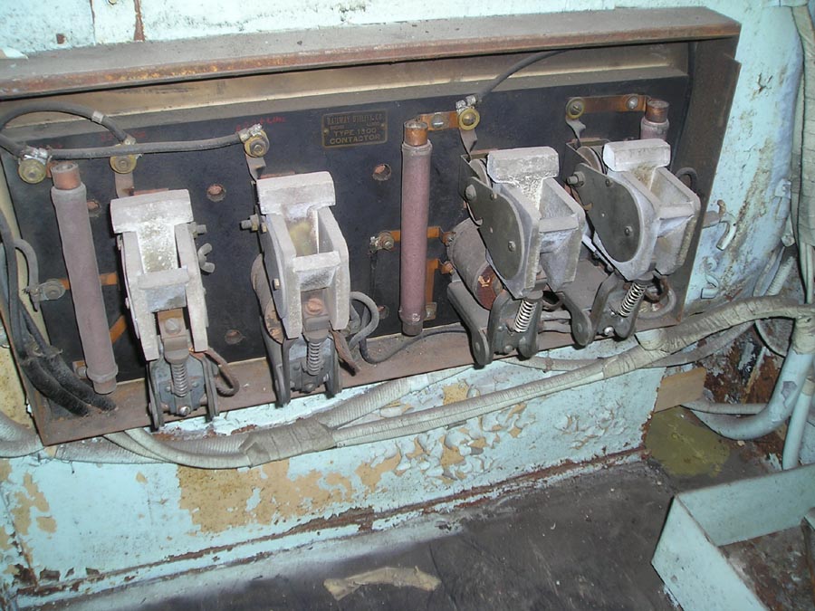
Below: The inside of the heating relay case, Railway Utility Co. Type 1900 Contactor.
From left to right, relays A, B, C, and D. In some cars, relay E is also in this
case. In this car, relay E is in a small box directly above this one.
Turning on switch 1 engages relay A, sending 32 volts through B to blower motor. When
B closes 600 is available to C and D, which close based on temperature and engage one
or both heater elements is blower.
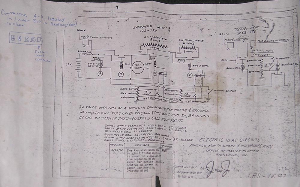
Below: CNSM drawing 1692, Electric Heat Circuits.
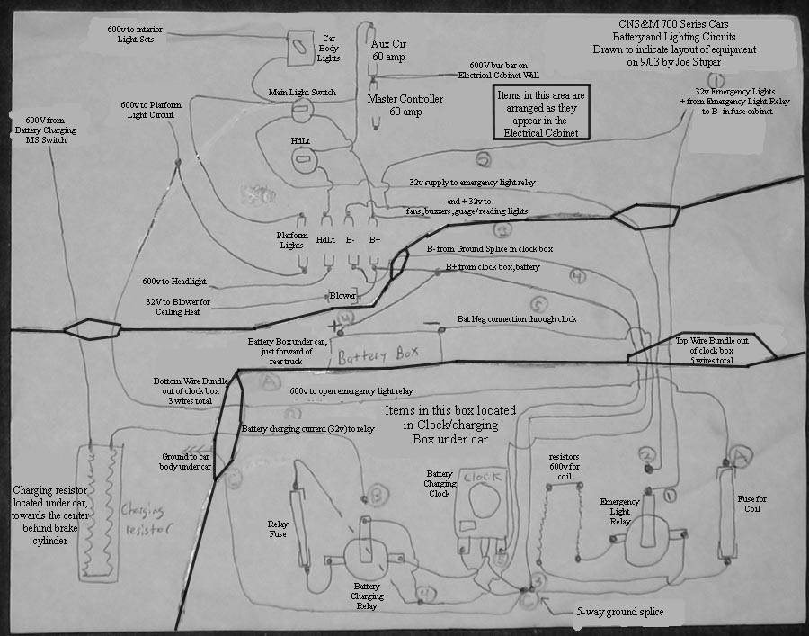
Below: Layout Diagram of Battery Charging Circuits.
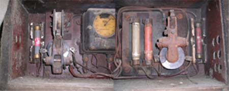
Below: A composite photo of the clock/charging box under the car.
Left is the charging relay, center charging clock, right emergency light relay.
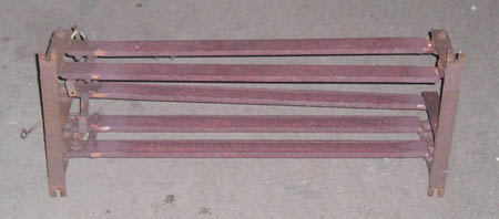
Below: An example charging resistor made of chromalux strips, created by the North Shore.
Important Note: There are exposed 600 Volt connections on these boxes!!
Above: The outside of the charging resistor box
Above: The terminals on the other side of the charging resistor.