


ORANGE COUNTY MODULE RAILROADERS, INC.
MODULE STANDARDS
The purpose of these Module Standards is to establish a minimum set of
specifications that
will enable a club member to construct a module that is compatible with modules
constructed
by
other members with respect to:
1. Interchange
- The ability to physically and electrically connect the module to
any
other club or member owned modules to establish a modular layout.
2. Reliable operation
- The ability of all members to operate, without derailments or
electrical problems, their HO scale locomotives and rolling stock from diverse
manufacturers that adheres to some minimum set of standards.
3. Esthetics
- Conformance to a minimum set of appearance specifications such
that a
complete club layout will have a pleasing appearance to the viewing public.
4. Safety
- The assurance that all club or member owned modules will conform
to the
fire and electrical safety regulations that are reasonably expected to be
imposed by
local codes, ordinances, or exhibit venue regulations.
Although it is expected that each member will be responsible for setting up his
or her module
and connecting it to the adjoining modules, the goal is that any member who is
familiar with
this standard will be able to physically and electrically connect any module to
any other
module or to determine by inspection that the modules are properly connected. In
addition, a
module that technically conforms to the letter of these regulations but does not
operate
reliably will be deemed to be non-compliant.
Within the rules established by these standards, members are free to establish
track
arrangements and scenery themes as they wish. Cooperation with other members is
encouraged and the club will take this into account when establishing the module
arrangement at shows. However, space restrictions and module availability at
specific shows
make it impossible to guarantee that modules will always be arranged in a
specific
configuration. Members are encouraged to consult with the Standards Committee to
determine whether a specific module configuration is reasonable in the light of
past
experience.
Variations on any of these standards must be approved by the Standards Committee
prior to
construction. If you have any questions about these standards, please consult
with the
Standards Committee before proceeding.
I. Construction
– The components of a basic module are illustrated in Figure 1.
A.
The module frame must be solid wood (no plywood or particle board except baltic
birch or
equivalent).
1. Use 1x4 or1x3 dimension lumber
(pine, fir, poplar) for main structure framing. The end
plate must
be1x4 as shown in Figure 1.
2. Joints must be glued and screwed
(#7x2" wood screws or 2" deck screws are recommended).
3. Longitudinal and lateral cross
members must be used as needed for stability, track
support, and to insure
that light weight materials used for the module surface will not
sag with age.
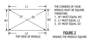
4.
The
module frame must be true and square horizontally and vertically.
A framing square and the measurements shown in Figure 2 will be
used to verify that the frame
is square
5. Module ends must be square with
the track center lines vertically and horizontally.
B.
Size
1.
Length must be an even multiple of two feet (2', 4', 6', etc.).
2. The most popular module width
is 24 inches. The maximum and minimum are 36" and 12"
respectively.
C.
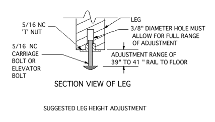
Legs -. The nominal height of the railhead is 40" from the floor. Height must be
adjustable
+/-1" from the nominal 40" after the module is set up. The legs must not
interfere with the
installation of the front plastic panels. One method of providing the required
height
adjustment is shown in Figure 3.
D.
Attachment - Modules are fastened together using 5/16 NC x 1 1/2" Hex. head
bolts, fender
washers (1 1/2"), and tee nuts.
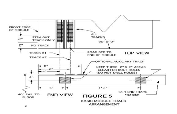
1. Bolt holes are to be located by
a club-supplied fixture and drilled by a Standards Committee member. See Figure
5 for approximate locations. The area in which the holes
will be drilled must provide clearance for a 5/16 NC tee nut and fender washer.
2. The tee nut is installed in the
left hand end of the module as viewed from the front.
E.
Finish - The module framework and back of backdrop must be painted flat black.
F.
Top Surface - The module top surface/sub-roadbed may be any material of the
builder's choice
1.
It must be secured firmly to the framework.
2.
In the area of the mainline roadbed, the surface must be flat and level.
3.
It must be sufficiently rigid to support HO scale trains powered by several
weighted
locomotives without deflection.
G.
Tunnels
1.
Tunnel portals and retaining walls must allow adequate access to the roadbed for
installation of the interface tracks.
2.
The interior of tunnels must be accessible from the rear or underside of the
module. The
Standards Committee will determine whether or not access is acceptable.
H.
Backdrops
1.
Backdrops are required on all modules except corners.
2.
Backdrops will be 8" above the mainline railhead.
3.
Backdrops must be painted a sky-blue color that will be specified and provided
by the
club.
4.
When the basic module scenery is continued onto the backdrop (e.g. mountains,
forests,
etc.) the height and color requirements may be waived by the Standards
Committee.
I.
Plastic on the Front of Modules
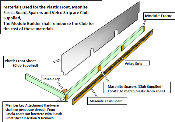
1.
All modules will have a clear plastic panel attached to the front of the module
as shown
in
Figure 4 at all shows.
2.
The club will provide the plastic, fascia board, spacers, and Velcro strip
Materials Used For the Plastic Front, Masonite Fascia Board, Spacers and Velco
Strip are Club Supplied. The Module Builder shall reimburse the Club for the
cost of these materials.
Member Leg Attachment Hardware shall not penetrate through Front Fascia board,
nor interfere with Plastic Front Sheet insertion and removal.
3.
The club supplied Velcro strip, shown in Figure 4, will be used for attaching
club
supplied curtains. It must be attached to the front of the fascia board 3/4"
below the top.
If
the Velcro strip is not self-adhesive, it must be attached with contact cement.
4.
The member will reimburse the club for the cost of the materials.
5.
Each member is responsible for transporting and maintaining in good condition
the
plastic front panel for his or her modules.
II. Main Line Track
- Each module must have, as a minimum, two mainline tracks
constructed according
to
these standards that will be powered and controlled by the club power supplies
at all shows. The
requirements for locating the main line tracks are illustrated in
figures 5 and
6. All other tracks are
known as Optional Auxiliary Tracks (OAT). The standards for main line track also
apply to the OAT
except as specified in section III.
A.
Rail Code - Code 100 nickel silver flex track will be used for all mainline
tracks.
B.
Location of Centerline (Figure 5)
1. Outside main line - 4" from
front edge at end of module
2. Inside main line - 6" from front
edge at end of module
C.
Minimum radius - 36"
D.
Main lines must be level with no grades
E.
Interface
1. Mainline tracks end 2" from the
end of the module. Figure 6 illustrates one method of accurately
establishing the 2” cutback.
2.
A minimum of 2" of straight track from the end of the mainline track to the
first curve in the main lines must be provided.
FIGURE 6
F.
Turnouts
1. Code 100 nickel silver rail.
2. PECO (ELECTROFROG) and
Shinohara, are suggested brands. Other brands of similar
quality and operating characteristics are also acceptable with prior approval by
the Standards Committee.
3. The minimum frog number is #6
(or PECO medium radius). #8 (or PECO large radius)
should be used where possible, and are required for main track crossovers.
4. Dead frog turnouts shall not be
used.
5. All turnouts must be gapped on
both legs of the frog, with one exception. If the turnout is
a
spur that can NEVER be connected to another track then the spur side of the frog
need
not be gapped so the turnout can be power routing. In that case, power drops
must not be
added to that rail.
G.
Joints and Gaps
1. All track joints within the
module must be soldered.
2. All insulating joints (gaps)
must be filled.
H.
Roadbed (if used)
1. Wood, Homosote, and cork are
acceptable materials.
2. Other materials must provide
adequate support to prevent the track from shifting under a
train. Non-rigid foam roadbed is specifically prohibited.
3.
Roadbed must extend to the ends of the module.
I.
Track Alignment
1. Transition from straight track
to curved track must be tangent with no visible kinks.
2. All track work shall be made up
of smooth transitions and short “S” curve type track
work is not allowed.
III. Track work for OAT (Optional Auxiliary Tracks) –
Optional Auxiliary Tracks are optional and are at the discretion of the module
owner. Club members are encouraged to have OAT trackage as it adds operational
opportunities to the club layout. All track work for OATs shall conform to the
standards for main line track with the following exceptions.
A.
Lighter rail may be used such as code 83 or 70, but the rail must transition
back to code 100 rail
in
the last 1½ inches of track before the end of the module. (The module interface
connector
tracks may not be used to transition track size.)
B.
The minimum radius is 18 inches (however it is suggested to try and maintain a
minimum of 24
inches).
C.
Smaller turn-outs are also allowed but they must not have dead frogs.
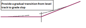
D.
Grades are allowed on the OAT tracks. If the track runs trough the module and
can be
connected to other modules at either end then the grade can not exceed 2% (1/4"
per
foot) and the change from level track to grade must be a vertical curve as
illustrated
in
Figure 7.
E.
Tracks that do not connect to other modules can exceed the 2% requirement.
F.
For members who are adding OATs that are of different gauge (HOn3) and the track
is intended
to
connect to other modules then all the above rules apply. If the track is
independent of the
main lines the track work must at least be prototypical and it is suggested that
the above rules
be
followed.
IV. Track Power Wiring
- All track power is passed from one end of each module to the
other by means of a continuous track power bus with feeder wires soldered to
each section of rail. Connections between modules are accomplished by means of
commonly available Cinch-Jones (TRW) 2-pin connectors.
Color coded wire shall be used to simplify trouble shooting. For more
complex track/wiring arrangements a
wiring diagram shall be affixed to the module. The following specifications must
be followed.
A.
Track power bus wiring
1. The bus wiring shall be 14 gauge
or larger and shall be color coded to match the track it
services. The bus wire connected to the inside rail shall be color coded to
match the
track, RED for the outside main, YELLOW for the inside main, and BLUE for the
OAT’s. The bus wire connected to the outside rail on all tracks shall be white
or black.
These are three separate pairs of wires, there is no common rail.
2.
All three buses must be present on every module.
3.
The bus wires must be run under the respective tracks and must not hang below
the edge
of
the module.
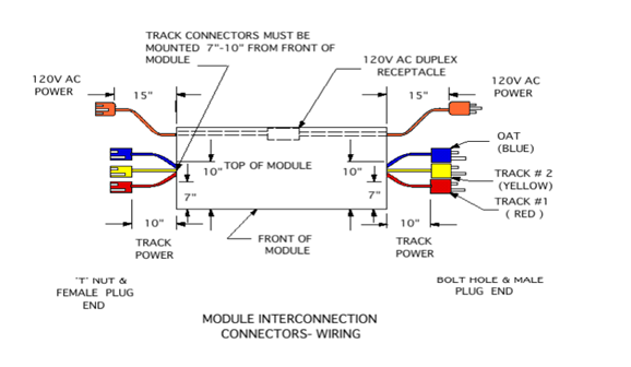
4.
A 10 inch stranded 2 conductor, 14 gauge or larger, pigtail must be provided for
each bus
at
each end of the module for connection to the adjoining module. The pigtails will
be
located 7"–10" from the front of the module using the connectors described in
section D
below. (Figure 8)
B.
Track feeders
1.
Track feeders shall be 20 gauge or larger solid wire, color coded to match the
bus wiring.
They must extend no more than 5-6 inches below the table top.
2
Each rail must have a track feeder at each end of each module.
3.
Each section of rail must have a track feeder irrespective of the length of the
track
section.
4.
Track feeder connections to the bus wires must be soldered (or made using
approved
suitcase connectors).
C.
Terminal blocks - Terminal blocks must be affixed to the end board at each end
of the module
for making connections between the power bus wiring, and pigtails. Additional
terminal blocks
should be used as needed to keep more complex track/wiring arrangements neat and
traceable.
D.
Interface connectors - Cinch-Jones 2-pin connectors (TRW # P-302-CCT &
S-302-CCT).
1.
The male connector shall be on the right hand end as viewed from front of
module. The
female connector shall be on left hand end. (Figure 8)
2.
The large pin must be connected to the outside rail of the track and the small
pin to the
inside rail. The wires must be soldered to the connector pins.
3.
Connectors will be color coded with paint or plastic tape. The purpose of color
coding is
to
make it possible to accurately and rapidly electrically connect modules together
and
to
easily verify the connections underneath the modules in poor light. Therefore
the color coding must be conspicuous and must be maintained in good condition by
the module owner.
a.
Outside mainline - RED
b.
Inside mainline - YELLOW
c.
Optional Auxiliary Track (OAT) - BLUE
4.
Where a member's module is composed of two or more smaller modules which are
always connected together, alternate connectors of the owners choice may be used
for
the internal connections provided that the reliability and current carrying
capacity are
equivalent to the Cinch-Jones connectors specified here. The wires must be
soldered to
the connector pins unless otherwise recommended by the connector manufacturer.
E.
Power Supplies/Throttles - All tracks will be powered by and all trains will be
controlled by a
club specified Digital Command Control (DCC) system. Member owned equipment such
as
throttles or DCC boosters connected to the club layout must be compatible with
the club
specified system and configured as specified by the club. All configuration
issues will be
resolved by the chairman of the Standards Committee or his delegate at each
show.
V. 120 Volt Wiring - Each module must provide a 120 volt, 60Hz. AC circuit to pass power from one end of the module to the other. A duplex receptacle to provide power for hand tools, soldering irons, DCC boosters, auxiliary power supplies, etc. must be located near the center of the module. All components must be UL (Underwriters Laboratory) approved and all wiring must conform to the National Electric Code.
IMPROPERLY OR INCORRECTLY DONE 120 V. WIRING IS DANGEROUS AND CAN KILL YOU. IF YOU DON'T KNOW HOW TO DO IT CORRECTLY, ASK FOR HELP BEFORE YOU MAKE THE MISTAKE.
The following
specific provisions apply:
A.
A 16 gauge or larger 3-wire insulated cord must be used.
B.
The receptacle and all 120 V. wiring must be located inside the back edge of the
module.
C.
The male plug is located at the right hand end of the module and the female plug
at the left hand
end of the module (as viewed from the front - see Figure 8)
D.
Both plugs must hang a minimum of 15" below the end board to provide sufficient
cord to
connect modules of varying widths.
E.
The cord must be fastened to the module and not hang below the module frame
except at the
ends. Metal fasteners may not be used.
F.
A plug strip with a circuit breaker or surge protector may not be used as the
required receptacle.
VI. Clearances
- There must be adequate clearance between the rails and scenery
and structures to permit operation of models of the largest prototype equipment
commonly operated by Class I railroads.
A.
Scenery between the rails such as grade crossings must not protrude above the
rail heads.
B.
Ballast must not be piled above the simulated spike heads or tie plates.
C.
Flangeways must be wide enough for free passage of all model trucks and must be
clear of
ballast and other scenery materials.
D.
Horizontal clearances on tangent track must conform to the NMRA Standards Gauge.
On
curves, there must be a minimum of 1 1/4" between the track center line and any
portion of any
structure or scenic element. This is consistent with the requirements of NMRA
Standard S-8.
E.
Vertical clearances must be adequate to permit unimpeded passage of tall
equipment such as
"double-stack" trains. The minimum vertical clearance on the two main tracks is
3.5 inches
with a flat top equal to the full width of the NMRA Standards Gauge.
VII. Interface/Setup Requirements
- Each
member must provide the hardware required to connect the left hand end of his or
her module to the adjoining module and is responsible for establishing that
joint at each show.
A.
Bolts - Two 5/16 NC (minimum length = 1 1/2") with fender washers to
mechanically join the
modules.
B.
Interface Tracks – The club will provide the interface tracks for all standard
modules. A member
exhibiting a non-standard module must provide the interface tracks as herein
provided or as
required by the Standards Committee.
C.
Setup - Each member is responsible for connecting the left hand end of his or
her module to the
adjoining module at each show. This includes adjusting the height of the
modules, leveling the
joint, bolting the modules together, installing the interface tracks,
establishing the electrical
connections between the modules, and mounting the plastic on the fronts of the
modules.
Before installing the interface tracks and establishing the electrical
connection the member must
determine, by consulting the setup plan or the member responsible for the setup,
whether or not
electrical gaps are required. The club will supply the plastic rail joiners. The
plastic should not
be
mounted on the front of the modules until all interface tracks have been
installed on both
ends of the module.
VIII. Exceptions, Additions, and Alternate Techniques
A.
NMRA Standard Modules - Recognizing that some members may have, or wish to
build,
modules conforming to the NMRA module standards, the following provisions for
NMRA
Standard Modules have been adopted.
1.
An exception to these standards is granted to modules that are constructed
according to
NMRA standards MS-1.0 and MS-1.3.
2.
NMRA Standard Modules must conform to all provisions of this standard that do
not
conflict with MS-1.0 or MS-1.3.
3.
Each member exhibiting an NMRA Standard Module must provide the interface tracks
required to connect the module to other NMRA Standard modules and to modules
built
according to this standard.
4.
Each member who wishes to exhibit an NMRA Standard Module must provide
temporary trackage extensions that are sufficiently rigid and adequately secured
to the
roadbed to permit the club fixture to be used to drill the bolt holes in the
ends of the
module.
B.
Alternate Construction Techniques - These standards are not meant to preclude
the use of
alternate construction techniques that appear promising for construction of
lightweight
modules. In particular, there have been several articles in the model press
regarding the use
of
steel studs to make a very lightweight rigid module frame. Members wishing to
use
alternate construction techniques shall have their design approved by the
Standards
Committee before starting construction. Prior approval of a design by the
Standards
Committee shall not exempt the completed module from complying with the other
requirements of this standard, particularly but not limited to rigidity and the
method used to
connect modules together. Note that this may require that the end boards be
wood.
C.
Existing Modules - Existing modules that have been approved as meeting the
provisions of
the 1996 Standard and the “ Upgrading Existing Module Wiring for DCC” document
may
continue to be used as long as they are maintained in good operating condition.
Modules
that require significant changes shall comply with this standard unless the
Standards
Committee determines that a particular change is unnecessary and/or
unreasonable.
APPROVAL:
These standards were approved and adopted by the club membership at
the regular business
meeting on January 13, 2010
UPDATES:


