


| The boiler stats: | |
| Weight |
460# (without tubes) |
| Design operation pressure | 200PSI |
| length | 6' |
| width |
13.5" |
| design bursting pressure | 1300PSI |
| safty factor to metal yield |
5.5 |
| HP output | 4HP (should be able push it to about 6HP) |
| tubes | 24 7/8 copper (3/4" hard "K" tubing) |
| grate area |
130 sq in |
| heating area (firebox) | 554 sq in |
| heating area (tubes) | 2064 sq in |
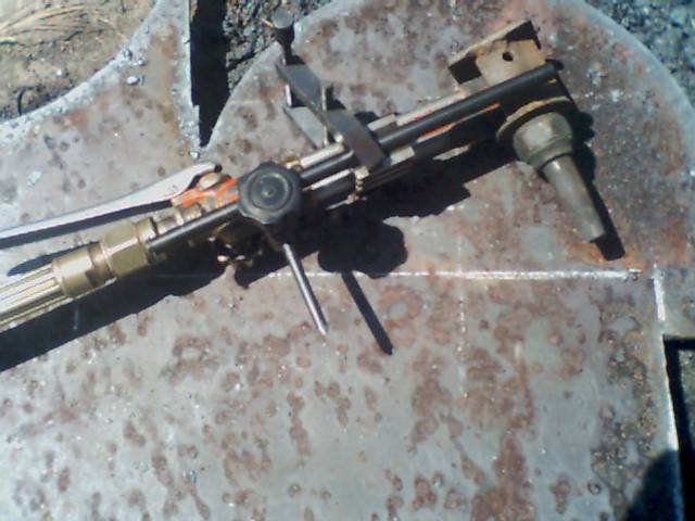
Torch cut 3/8" plate for fire box and sheets. I use a simple straight edge and circle cutter attachment for Victor torch. The protractor is made up of a V block, parallel clamp, parts from a surface guage and a 1/4" pointed drill rod. With this setup I am able to cut lines and circles to +-.030" with no post machining required. The gizmo on the head, under the tip nut is to attach the Victor torch to a pipe beveler to cut pipe +-.030" |
 |
|
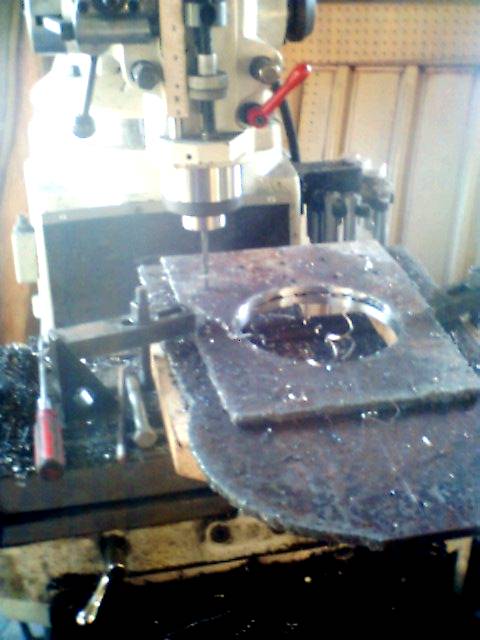
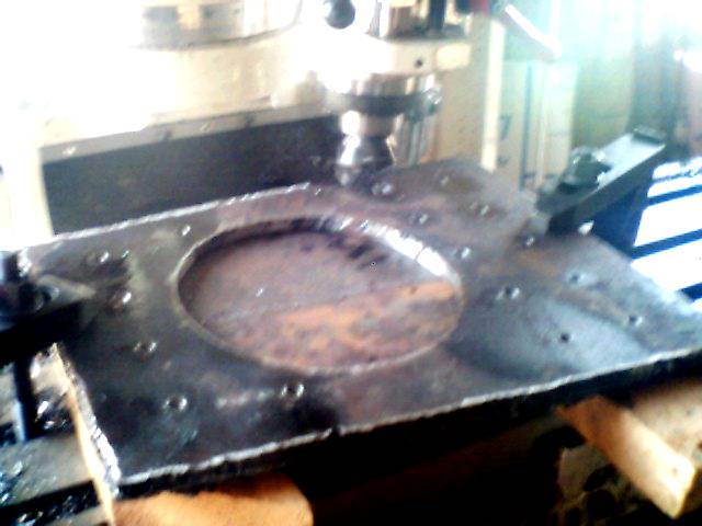
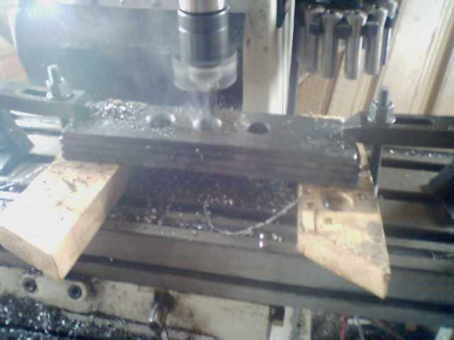
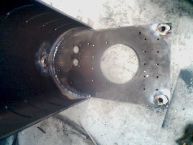
Drilling 3/8" stay bolt holes in fire box back and boiler back. The large hole for the 6" pipe fire door was machined after torch cut by using a boring head and carbide cutter. These sheets will be set 1.5" appart to form the wet back of the boiler. |
 |
|
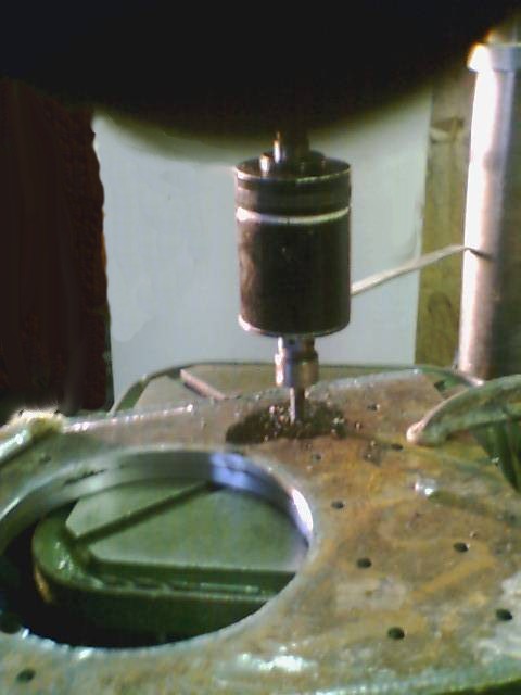
Using a Tapmatic R5 tapping head in the drill press at 300RPM to tap stay bolt holes. Tap inside and back sheet clamped to align threads. Because the tap has 16 threads/inch you can just open the gap to 1.5" an the threads will all line up. The first tap only did about 25 holes before I hit a hard spot in the plate, the second tap finished the rest of the 140+ holes. I have never been able to resharpen taps by hand to work well in the tapping head. While you could hand tap these holes, the tapping head allowed me to tap all the holes in about 4 1/2 hours. |
 |
|
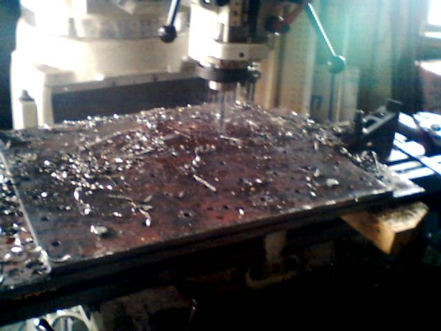
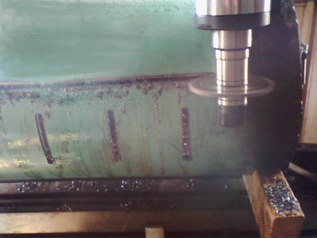
Drilling the 54 stay bolt holes in each fire box side sheets using the Bridgeport mill. Hard to see here is the 0.125" offset of the inside and outside plates to compensate for the angle they sit on the boiler. This angle and the 1.5" spacing create a 1/8" shift in the bolt alingment. Drilling and tapping these 54 holes took 3 hours per pair of side sheets. |
 |
|
Milling edges of fire box sides. While most of the edges don't require high precision, the sides of the inside and outside front and rear sheets and the width of the inside side sheets set the shape of the box and are milled togeather to square the box. These parts were torched 1/8" ov The 2" carbide tipped cutter works well to clean the torch cut edges. rsize to allow milling. |
 |
|
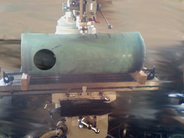
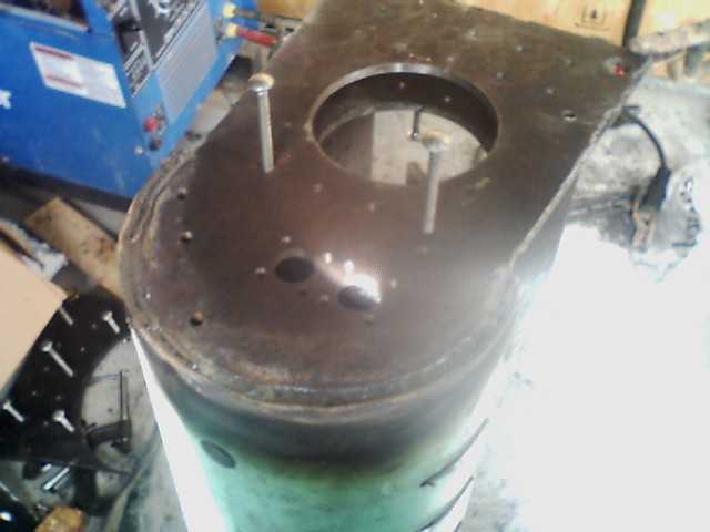
With the 12" pipe clamped in saddles made from 2x4 cut to OD of pipe mill the steam dome hole for 6" pipe OD. Left, mill slots for the 4 crown trusses. These should be cut .060" oversize to allow the fire box to be removed and re-inserted druing the welding process. These slots will be welded over with the ends of the truss plates. |
 |
|
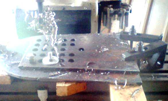
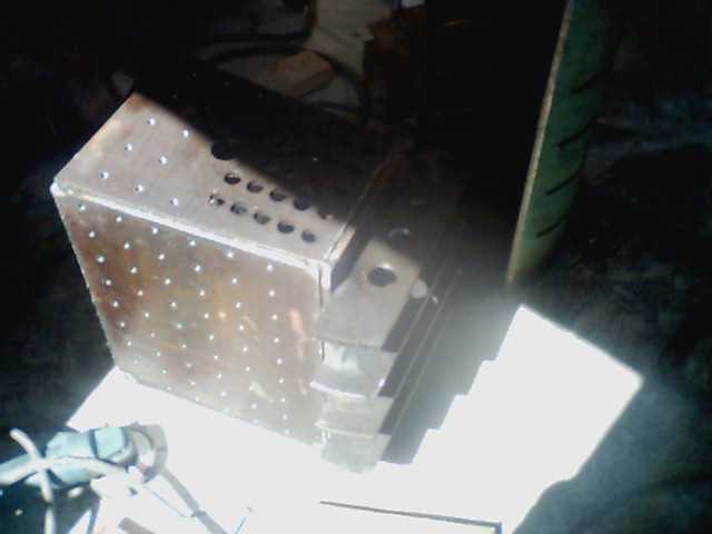
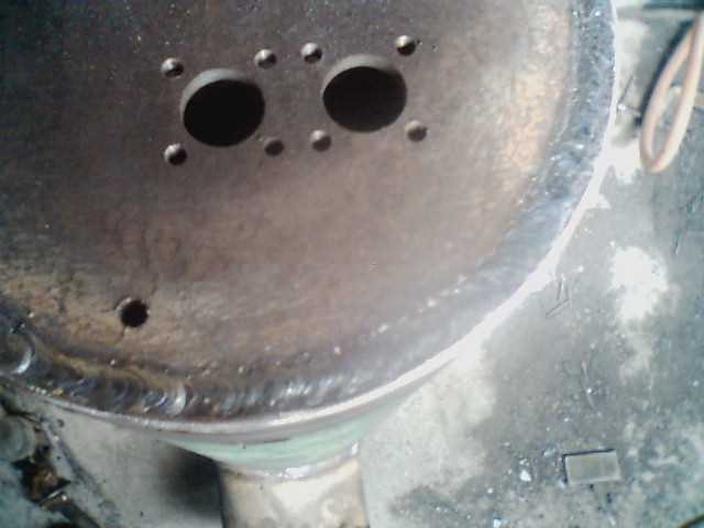
| Drilling the front and rear tube
sheets with a 7/8" drill ground .004" off center the holes come out
.008 over size. This is good clearance for the copper
tubes. The front tube sheet, rear tube sheet and front outer fire
box sheets are clamped for drilling. The tube holes and stay bolts can all be done in one setup. |
 |
|
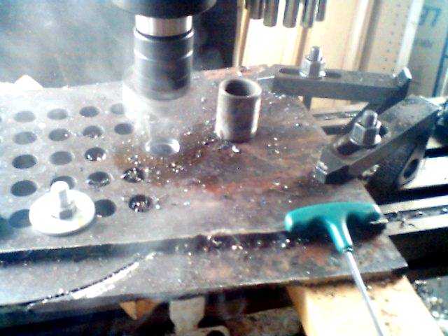
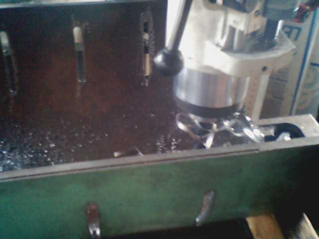
| Using boring head to open hole
for the 1" pipe coupling. This sets in the bottom of the boiler
where it provides acces and a place for a zinc water heater
anode. The coupling shown will later be cut in half and welded
into the front and rear tube sheets. |
 |
|
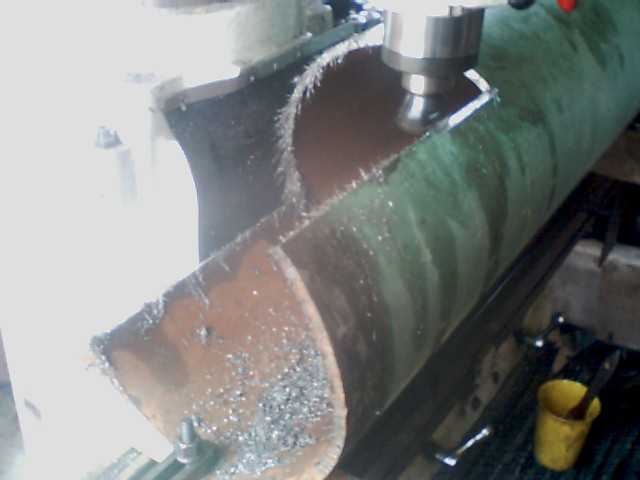
| Using a sliting saw to split the
upper rear of the boiler. This job needs more accuracy than the
torch can do. |
 |
|
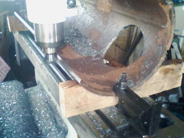
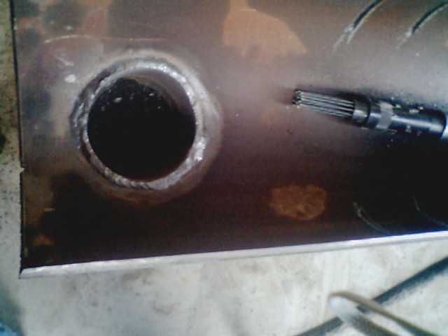
| With the boiler upper rear
section split you can now drill and bore a hole for the manifold.
The hole is sized for a 3/4" pipe coupling split in half. |
 |
|
| Beveling the upper rear of
pipe for welding. |
 |
|
| The second section of 12" pipe
is cut to lap under the upper rear. Here the edges are beveled
for
welding. The fur on the edge is a result of magnetic field concentrated by cutting the pipe. As the pipe was slit it's cuttings formed arched field lines. |
 |
|
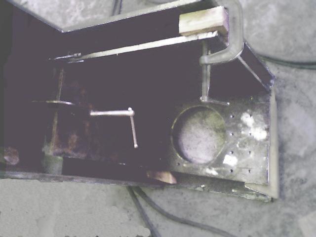
| Here the 4 crown truss plates
are being bored to pass the throttle link and blower pipe. |
 |
|
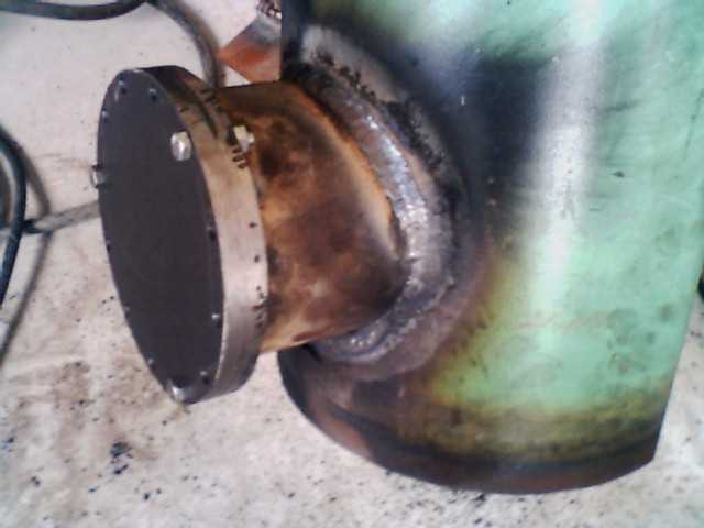
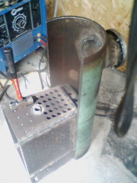
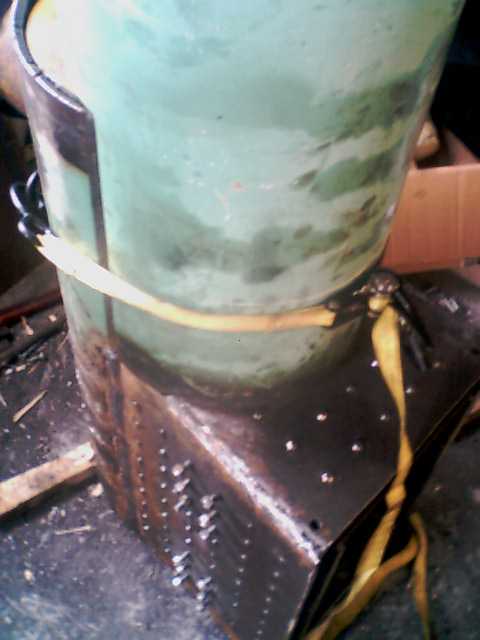
| Now we get to start the
welding. Here the steam dome is welded to the upper rear of the
boiler pipe. Note: the green paint is epoxy coated gas main. This is new gas pipe and worked well for the biler. |
  |
|
To weld the fire box you assemble all the sheets with at least 5 stay bolts in each pair. Be sure the gap between the sheets is equal. If you don't get the sheets parallel you won't be able to get the stay bolts in. All this assembly is to locate the crown sheet so you can tack weld the crown truss plates . |
 |
|
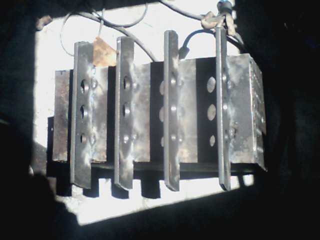
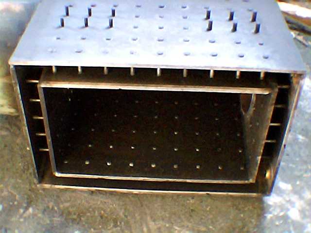
With all the fire box sheets in place you can insert the 4 crown truss plates and tack weld. |
 |
|
You must tack the back truss first then insert the next and tack it. Continue inserting and tacking all 4 plates. (sorry about the sun in this photo) |
 |
|
After tack welding each crown turss plate tack weld the inner fire box plates. Rremove the outer sheets. Now shift the inner fire box to one side and you can remove the tack welded assembly. |
 |
|
To minimize warpage when welding add more tack welds to the crown sheet and truss plates. |
 |
|
The key here is to minimize warpage when welding the trusses. Weld in a balance, weld a section on one side of the truss then the other. After the center 2" is welded on each side weld the outter portion on each side. The weld shown at left is a 2 pass fillet extending 1/2" out on the crown and truss. Weld in the melt plug coupling into the crown sheet. The crown sheet is the most likley place for a boiler to explode so don't skimp here. |
 |
|
Now a bit of fun..... Even with carefull welding of the truss plates you will most likely not be able to re-insert the fire box back into the upper section of the boiler pipe. When you milled the slots for the truss plates you should be sure to make the spacing close to 4". Now using calipers and a big red handled high persision persuader, an intersting combination, you re-align the plates. With a bit of work and several attempts, things go back togeather well. Add more tacks to the inside sheets and fillet weld the inside corners. You can remove the fire box again and weld the outside corners. |
 |
|
With the crown trusses still free to move replace the back sheet and insert stay bolts. Using a hand grinder make any fit adjustment you need to the back sheet. Weld the back sheet to the upper pipe on the outside. |
 |
|
Good design, good fit, good preperation and clean joints make good welds. Here done with stick welder 5/32" 7018 rod at 230 amps DC. This beed is 3/4" wide. |
 |
|
Then remove the stay bolts and remove the fire box again. This gives you access to weld the inside of the back to pipe. Now braze the 3/4" manifold coupling into the pipe and the two blow down 3/8"pipe couplings into the back sheet. |
 |
|
The two back trusses are now welded in. The lower truss needs special attention. It is in line with the crown sheet and could require grinding the center out to allow the fire box to be re-installed. A clearance of 1/16 to 1/8" is best. This gap will be welded later connecting the crown sheet to the back sheet. This weld is done after the rest of the fire box is welded and the crown trusses are welded. You must reach in the fire door opening with a full welding rod, past the 4 stay bolts near the lower back truss. You can also reach the back 1.5" of the side seams through the door hole. |
 |
|
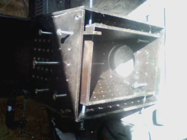
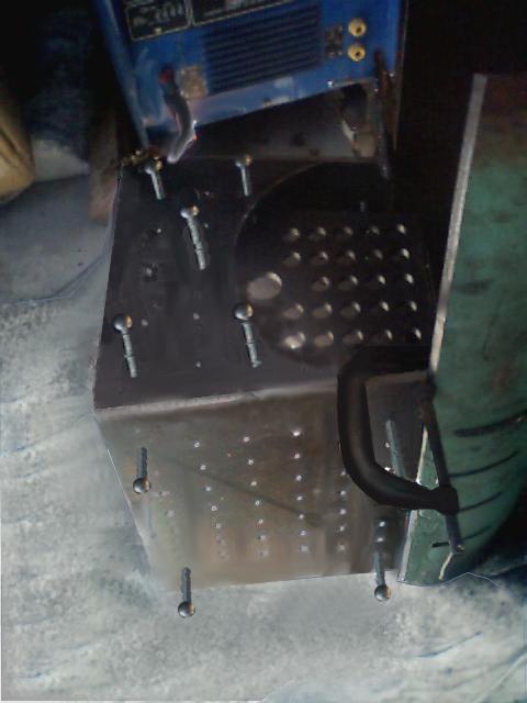
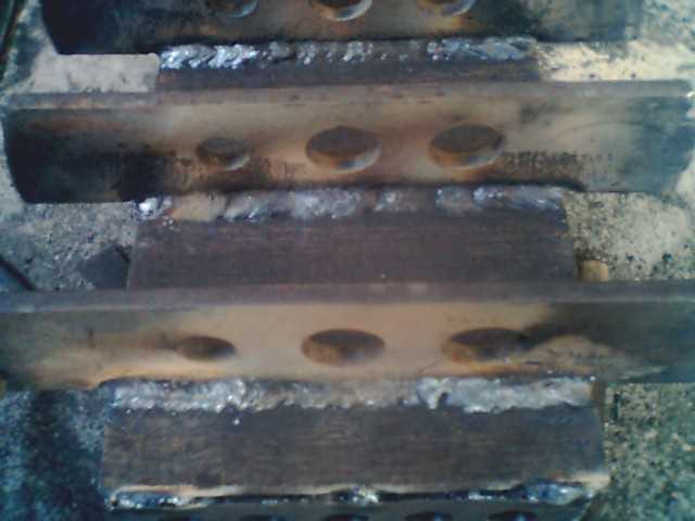
| Replace the outer side sheets
and install the stay bolts. As the stay bolts are installed cut them off 3/16" above the sheet. Set the ends of the bolts like rivets. A 401 impact hammer is just enough to do the 3/8" bolts. If you use the 1/2 sledge and mash the bolts to the correct hight then the 401 hammer does a nice job of forming the end of the bolt. Stay bolts took 3 full days of work. Just stay with it and keep pluging and before you know it you will run out of holes. 12 bolts on each side and 2 on the back sheet are left 3/4" inch long for mounts and fire door. After the stay bolts are finished you can weld the outer fire box seams. All seams can be welded inside and out, except I was unable to reach the back 6" on the inside joining the upper pipe to the side sheets. The penitration on the beveled outside weld is good enough that the inside weld is just extra. Before installing the fire box door pipe reach inside and weld the crown sheet to the back truss. Here you see the pipe for the fire box door ready to weld. The fire box ended up within 0.040" of the design position. |
 |
|
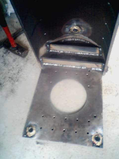
With the lower front pipe fitted and a strap clamp holding it in place it is ready to weld. The outside seams are tacked and welded with a single pass 3/4" wide full penitration beed. All inside seams can be reached by working down the steam dome pipe. The cresent between the 2 pipes and the 2 gussets are added. Three 1/2 inch stay bolt holes are drilled in the side of the upper section of the boiler on each side and three 13"x1/2" rods are welded in. The oval shape of the boiler just in front of the fire box requires these 3 horizontal stays. |
 |
|
Ready for the 4 3/8" strips that form the mud ring. |
 |
|
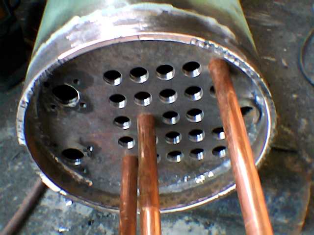
| Weld the 1" pipe coupling into
the bottom of the front tube
sheet from the inside. Do not braze this, the brass would mess up
the weld since
it is so close to the weld attaching the front tube sheet to the
main boiler pipe. Use at least 3 tubes to align the front tube sheet with the back tube sheet. Be sure the 2 sheets are parallel and alligned with a 36" spacing. Use oak dowels soaked in watter to plug the holes near the fillet weld. Cover all others to keep weld splatter out. I did run a 3/8" tap in the flange holes again after welding. The 3 tapped holes near the weld were a bit tight but would have worked well without re-tapping. |
 |
|
| From start to finish the boiler
took 68 hours to build over 2 1/2 weeks averaging 4 hours a day. The calculated bursting pressure is just over 1300 psi. The yield point on the stay bolts is 1100psi (boiler pressure). This gives a safety factor of better than 5 to 1. The tubes crush at 2200 psi and the boiler will be operated below 200 psi. Tube rolling not done yet. May 18, 2004. |


