Start by carefully removing Mr. Rubber with
a small pair of pliers. Gentle lifting will separate the lil guy
from the swing arm. Set 'im aside. The "rivets" on the 977 caboose
are splined pins. They're easily removed by rapidly heating them
with a soldering iron. I used a well tinned chisel-point soldering
iron of about 75 W capacity. If you keep the tip scrupulously clean by
frequently wiping it on a wet sponge, it won't mark the splined pins with
any solder. I simply heated the pins for about ten seconds each, and pulled
each one straight out with a pair of needle nose pliers. Easy!

Next I placed the caboose on the bench with
the solenoid assembly to my right. I then snipped the wire that leads from
the uninsulated truck; I cut it about 1/4-inch back from where it's staked
to the solenoid coil. That way, there's no strain on the coil termination
itself. By the way, Gilbert expertly left a tiny "service loop" at the
truck. That's a nice touch which gives the stranded wire an extra measure
of flexibility as the truck swivels. Don't pull the wire too tight and
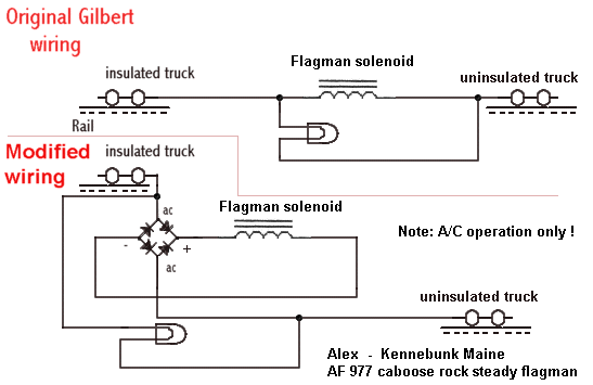
crimp that little loop. I left the original lamp wiring in place and clipped
the wire leading from the insulated truck (opposite end of caboose) where
it terminated on the solenoid. This left the solenoid isolated; the original
wiring has one end of the solenoid connected to the uninsulated truck.
Next I installed a "block"-style full wave
bridge rectifier next to the lamp, using a small piece of double-sided
tape to hold it in place. The rectifier I had in my junkbox was rated at
a hefty 15 Amps. It was originally intended for use in a power supply for
a 100 W stereo amplifier! It measures about 1.25 inches square and perhaps
3/4 of an inch high--including the terminals. Overkill, but who cares?
You could substitute four discrete 1 Amp diodes (such as 1N4001 or 1N4002
types) for the preassembled bridge (I described this in my notes for the
reversing handcar). But, if you purchase an insulated bridge, as mine was,
so much the better. By the way, some bridge rectifier assemblies have a
metal base. If you get one of those, take care to insulate it from the
circuitry inside the caboose.
Now, solder the lead from the insulated truck
to the "ac" input terminal (either terminal will do) on the bridge. These
terminals are sometimes marked with a little squiggly sine wave symbol;
sometimes they're marked "ac." Solder the stranded wire from the uninsulated
truck to the other "ac" input on the rectifier block.
Then wire the (+) and (-) outputs from the
bridge to the solenoid. Polarity doesn't matter.
That's all there is to it. Reassemble
the caboose. It's not hard to do.
I found that the splined pins simply press-fit
back into place without the need for any adhesive or heat.
Put the flagman back on and press him into
place. Place the caboose on the track and apply the throttle. You'll find
that the flagman is now stable and quiet! However, there is a caveat. You
MUST now run your caboose on ac. It will not
work on dc trackage.
By the way, I initially tried using a simple
single diode half wave rectifier and a 100 microfarad electrolytic filter
capacitor, but the solenoid didn't like half wave DC. It chattered. The
bridge is the way to go.
Return
to S-Trains Navigation Page