AF motors & rectifiersHow
to wire an AF motor for DC Polarity reversing and eliminate the reversing
unit. by Chuck Smith cesmith@eznet.net
This is how an AF series wound motor is
wired. The reversing unit wires are removed in this view for clarity.
Power supplied is AC or DC.
This shows the full wave rectifier inserted between
the armature and the field. Only DC power is supplied.
The rectifier has four leads, two marked as + and -.
The + and - leads are the "output" and will serve to keep the polarity
of the field constant when the input polarity is changed. This reverses
the motor in exactly the same way as the reversing unit, by reversing the
polarity between the armature and the field. The motor now can only
run on DC. The direction of the motor should ideally be set to forward
movement with the RH rail +. This can be accomplished by interchanging
the output leads. The input for the 'rectifier' example above is
directly from the tender pick up (for steam engines) or power leads (for
diesels). The rectifier could alternatively be wired across the armature
and the result would be the same.
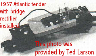
Here is a picture of a rectifier installed in a tender.