


| You can save yourself many hours of work by building a simple motor
tester. This device bypasses the reverse unit and is wired directly
to the motor, so it allows you to run the motor to determine its condition,
pinpointing any problem quickly.
Most American Flyer wiring systems can be tested, along with other AC-powered electric trains. This tester will not check units with a two-step reverse unit, such as five-digit steam and diesels, because they are wired direct and have no neutral position. I find it very useful to know where the problem is prior to disassembly, or to verify that the repair was completed and test it prior to installing the body shell. If a locomotive does not run and will run with the tester, then the problems could be a broken wire in the wire harness, a bad drum/finger contact, etc. If a locomotive does not run with the tester then the armature could be bad, or the brush tubes are dirty so that the brushes are not making contact with the armature, etc. |
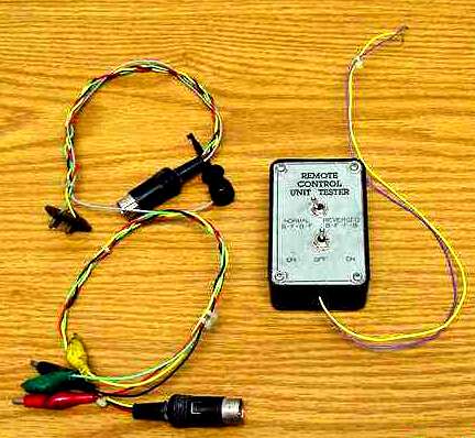 |
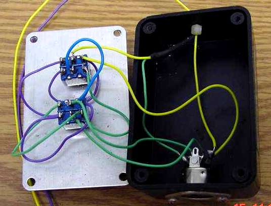
| Building the Tester
1. Drill a 9/16 hole in one end of a box (Radio Shack #270-230 or equivalent)
for the 5-pin chassis jack (RS #274-005), and two holes for mounting screws.
Drill a 1/8 hole for the two transformer leads in the opposite end of
the box. Drill two 1/4 holes in the lid for the toggle switches,
using figure #4 as a template for hole locations.
|
 |
| Using the Tester
To test a steam engine with jack panel and
Caution: Do not leave the power on if
|
 |
| To test a 5-wire steam engine:
1. Hook the AC input wires of the tester to the base and 7-15 volt posts of a transformer. 2. Plug the wire harness with the AF jack plug (figure #2B) into the tester and the jack panel of the locomotive. 3. Set switch A to off (center position). Set switch B to BFFB. 4. Plug the wire harness with the AF jack plug figure #2B into the tester and the jack panel of the locomotive. Then hook the loose gray wire with the micro clip from the harness to the fifth wire lug on the engine jack panel. The simplest thing to do is to remove the two jack panel screws and pull it out, and then clip the gray lead on the lug from the inside and from the top. This eliminates the need to unsolder that wire, but I prefer to unsolder it and get the tender out of the way. The gray wire is hot and should be kept from touching the locomotive when not in use. An additional on/off toggle switch may be installed to turn the gray wire off when not needed. Note: The fifth wire only supplies current to the smoke unit and headlight and is independent from the motor. |
 |
| To test diesels and all other equipment without jack panels:
1. Hook the AC input wires of the tester to the base and 7-15 volt posts of a transformer. 2. Plug the wire harness with the alligator clips, figure #3 into the tester. 3. Set toggle switch A to off (center position) then set toggle switch B to the BFBF position, because that is the only position that matches the color code of the harness. 4. Using the color code, hook the green and yellow wires to the brushes and the red and black wires to the field. See the label on the side of the tester for reference. 5. Now lock the remote control unit in neutral. (This is when two of the four figures are on the plastic part of the drum.) 6. Set the transformer to run half to three quarters speed; toggle switch A back and forth to run the engine in both directions; center position is off. This is great for aligning the field in diesel power trucks prior to installing them in a chassis. For any questions or comments, contact Shawn Solderitch, P.O. Box 252, Bath, PA 18014-0252. |
 |


