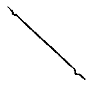
| STRAIGHT TRACK. This
is how a Straight Track section looks when it is drawn by your PIKE PLANNER.
Scaled-down track section measures from the center of the V-notch to the
center of the V-notch. |
CURVE TRACK.
This
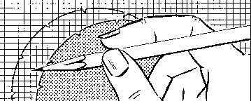
is how a Curve Track section appears. For accuracy, be sure to use
a sharp pencil held in a stright up-and-down position rather than at a
haphazard angle.. |
HALF STRAIGHT
TRACK. Many model railroadlayouts, especially the larget ones, will
require one or more half track sections, shown reproduced above.
It measures exactly one half the standard 10" length. |
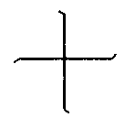
CROSSINGS.
The
inside 'L" section of the Pike Planner is to be used for drawing 90 degree
crossings,as illustrated here. When first "L" is drawn, thrn
Pike Planner and complete the cross. |
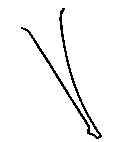
| RIGHT HAND
SWITCH. No model railroad is complete unless it has at least one pair
of switches for sidings, spur lines, etc. Above is shown a right
hand switch |
LEFT HAND
SWITCH. Left switches may be drawn by using the "C: cortion of
the Pike Planner (see diagram) or truning over the Pike Planner and using
"D", whichever is more convenient. |
| PARALLEL TRACK.
One
of the most interesting layouts is that which has parallel main line track
connected by two left hand switches. Dotted lines show track extention. |
|
|


