| Main Frame Modification Details
The main chassis frame has been modified by opening up the aperture on the non-powered end. This is to allow sufficient movement of the new motor-chassis for when it pivots and rotates without fouling the main frame when the track is uneven. 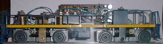 |
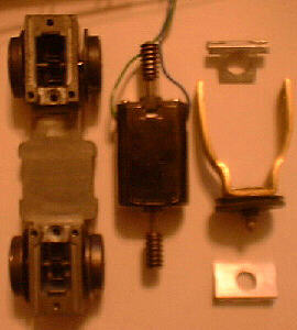
Additionally a new method of securing the chassis had to be constructed and this involved using an existing yoke from an old AF 370 GP7. It then had to be modified so that it would fit onto a new mounting bracket on the top of the main frame. | ||
|
With the chassis machined to the above measurements it was possible to maintain the axle to lay-shaft centre to centre dimensions as per the existing AF/LTI dimensions but using the Sagami motor armature shaft to replace the lay shaft assembly. One of the criteria I set myself originally was to utilise the existing gears on the chassis but I discovered that the bore of the worm is 3.175mm and the diameter of the Sagami motor was only 2.4 mm. | ||
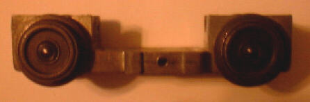 . .
I then debated what to do about the worm as its bore was greater than the shaft, I had thought about a sleeve but I felt it would not be accurate and so elected to commission North West Short Line to make some custom gears for me to fit there own worm. After calculating the size of gear I had a choice of two ratios, 23:1 using a single start worm or 11.5:1 using a double start worm. The latter ratio is also very close to the original ratio of 10:1 that uses a double start worm - I chose the 23:1 mainly to see what its scale running speed would be like. After stripping the chassis I removed the oilite bushes and machined the chassis to accept new axle bushes. I then machined the new bushes in a jig to a diameter of 4.1mm to accept the Lionel axles which are 4.06mm for a precision fit as opposed to Lionels wide axle bushes which are easier for assembly of axles due to the fact that the knurling for the gear is a greater diameter than the axle shaft. Each of the chassis are fitted with two traction tyres, this was because I had the parts to build it as such but in reality one per truck would more than suffice. The Sagami 1833 can motor has a bearing located in a housing in the main body at each end to support the armature. |
The dimensions of each housing differ in diameter, one being 7mm and the other being 8mm. The motor mounts are made from right angle stock material and have slots at the top for easy assembly of mount to chassis and each of the two mounts correspondingly has a 7mm or 8mm hole to support the motor. The motor mounts would need to be altered slightly so that you add additional material between underside of mount and top of chassis so that it will sit square. Also it would be advisable to make them in plastic as the prototype ones are aluminium and I had to insulate them on one side to prevent a short circuit from the brush end of the motor. |