Crossing Bell
Details
|
|
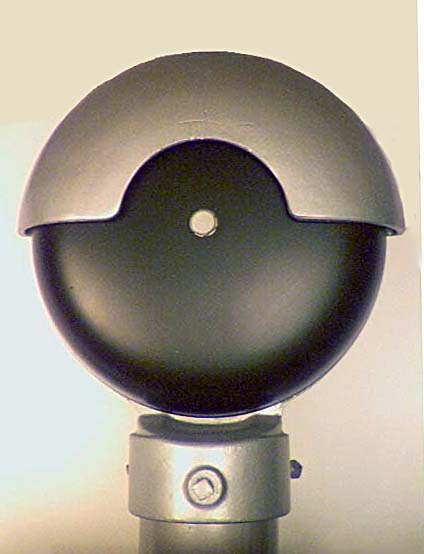
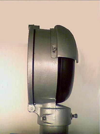
This crossing bell is typical of those used
at railroad crossings. More modern
bells have a similar shape but are roughly two-thirds the size. Earlier bells were also made in a teardrop
shape having a somewhat pointed top.
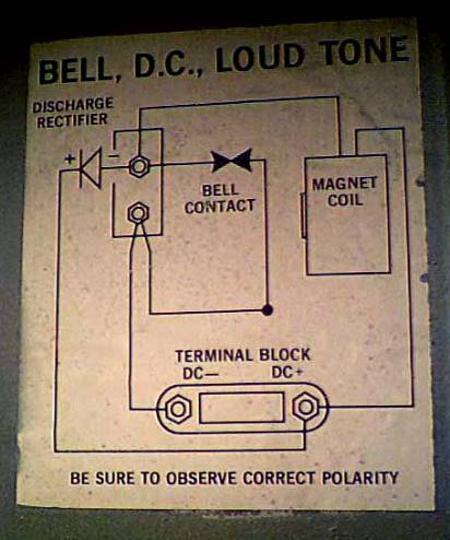
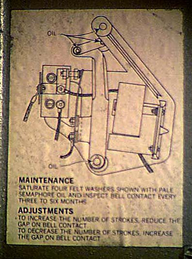
Above. Circuit drawing from inside back cover which shows how the circuit works. With no voltage applied, the bell contact is closed. Applying voltage causes the electro-magnet coil to draw the moving arm toward the coil which opens the bell contact. This in-turn de-energizes the magnet coil causing the moving arm to fall away from the coil, closing the bell contact and restarting the cycle. The number of strokes can be adjusted by increasing or decreasing the gap of the bell contact. The discharge rectifier is needed to protect the power supply from voltage spikes caused by opening the bell contact and de-energizing the magnet coil.. |
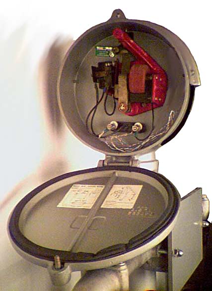
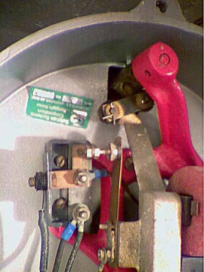
Left. Open back showing the electro-magnet coil (light red), bell
contact switch and moving arm (silver) which through a series of connecting
arms attaches to a bell striker on the other side of the case. The coil and switch operating together cause
the moving arm to swing from left to right causing a corresponding movement
of the bell striker on the other side of the case. The dark red piece holds the assembly to the back of the case
and does not move. The bell striker
is directly attached to the shaft going through the back of the bell case.
|