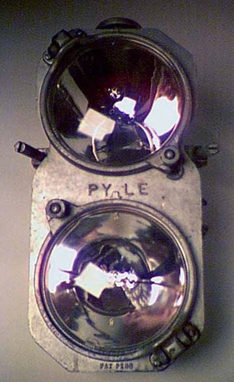
The 20585 Internal
Mechanism
|
|
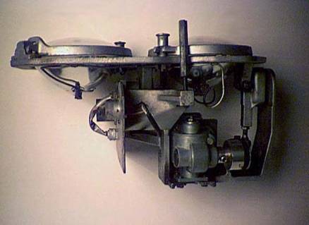
The mechanism is
removed by unscrewing the two slotted bolts on each side of the
gyralight. These slotted bolts screw
into threaded assemblies attached to each side of the gyralight housing.
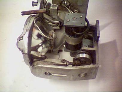
Above. Front view of mechanism. Note the slotted retaining bolts on each side. |
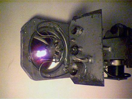
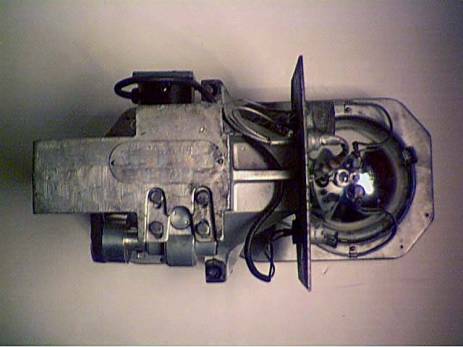
Above. Mechanism side view.
Above. Lower back of mechanism showing connectors for motor (top) and lights (bottom). |
|
|
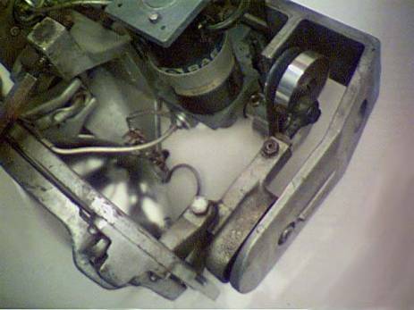
Photos of the motor and connecting components. The fixed ball joint is located in the middle of the unit. The motor is attached to the light platform on the top end through a heavy duty gearbox, a set of pulleys and a belt, an eccentric and a connecting slide. The slide moves in a reciprocating pattern when the motor is activated. This in turn causes the right hand side of the frame to reciprocate thus creating a circular or oval movement of the light beams.
|
|
|
|
Below. For completeness, a back view of mechanism.
|
|