TrainWeb.org Facebook Page
Repairs


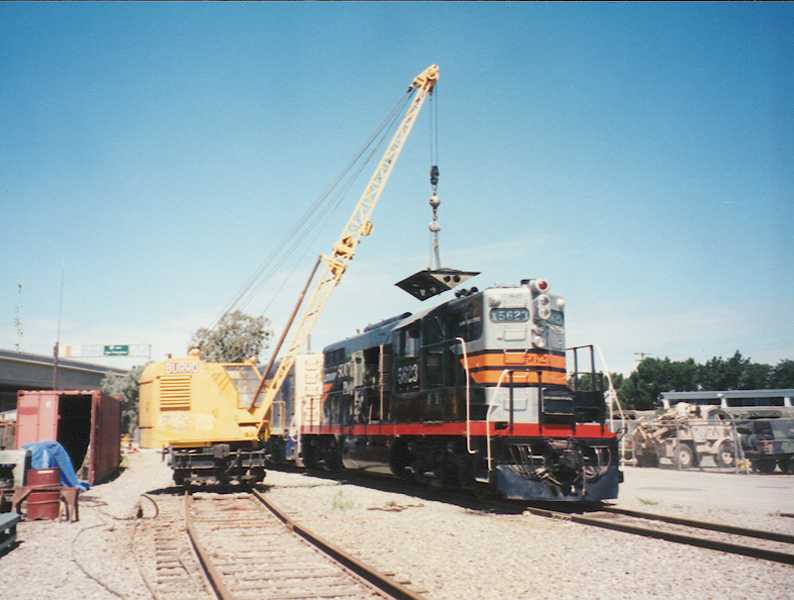
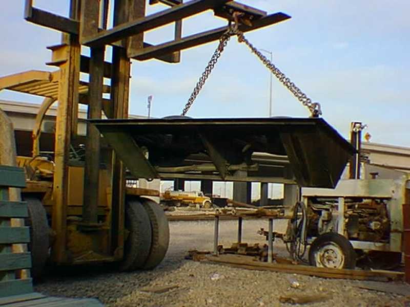
Any piece of machinery needs repair or TLC from time to time. The 5623 is no different except that there is SO MUCH of it to fail. This page will document those ongoing repairs needed to keep her running and, hopefully, looking good.  All photos on this page are mine.
The first major item that came up after the restoration was a leaking radiator. One day, in June of 1997, the OTR engineer reported that there was water running out of the shutters on the engineers side of the front radiators. Inspection revealed that the second core on the engineer's side was indeed leaking. All the hoping for a bad gasket or broken pipe did no good at all. So, I contacted a friend who had access to some S.P. locomotives being scrapped and was able to acquire a couple of cores at a reasonable price. Luckily, we had access to a Burro crane at the time and so, the job was done. One really irritating fact turned up in the process of pulling the front fan hatch. The air tanks were positioned just far enough forward so they lay over the top of the hatch by about an inch and it became necessary to remove the tanks. Now, I like EMD's but that was lousy design work. Of course, things are not supposed to break, are they? The second view shows the fact that there is one radiator section on each side, each one composed of 2, 27" sections bolted together in the middle. The replacement was a newer one piece 54" element. The cable looking things in the left front corner of the third view are the temperature sensor elements which screw into the radiator header and control the fans, temperature gauge and the hot engine alarm. There are actually 3 of them on each side. While cleaning the bay out, we discovered a 1977 penny, no doubt put there for good luck during GRIP. In keeping with the spirit of the idea, we put a 1997 penny in with it. The last 2 photos show the shutter actuating mechanism.


The first photo is of the old radiator element. The header on the right end is where the temperature sensors connect. The fan hatch laying on the ground shows the position of the two fans and the third photo shows the detail of the underside of one of the cooling fans. The 8 foot fork lift blades gives some perspective to the size of the hatch. Errol and Brian guide the new radiator element into place in the last photo. The fact is that we acquired 2 complete radiators which were in much better condition than the old ones so we replaced both front radiators. This gave us 3 spare 27" cores, just in case. There are, after all, more radiators at the rear of the hood.


While doing the required 92 day inspection in April, 1999, I discovered cooling water in one of the air boxes. This is not a good thing. Generally speaking there are 3 ways for engine cooling water to get into an air box: 1. A leaking "O" ring on the water return tube from the head (visible on the right side of the head in the third photo. 2. A leaking "O" ring on the water manifold jumper to a cylinder liner. 3. A blown liner to head water passage "O" ring. The first two are pretty simple to fix but the 3rd requires the removal of the head. In order to find the problem, I pressurized the cooling system with about 10 pounds of air, removed all the air box hand hold covers on the offending side of the block and waited. After some time passed and I turned the engine over little by little, water was seen dripping out of the intake port of the number 9 cylinder. Well, it couldn't be simple. The real danger in this type of leak is that it will let enough water into the cylinder to fill the space between the top of the piston and the head when the piston comes up on the compression stroke. Given that water is not compressible, what happens then is never good but generally leads to a bent connecting rod, at the minimum. The cylinder head and liner assembly is held down into the block by 4 "crabs". These are shown in detail in the "Engine" section of "Details". The crab nuts are torqued to 1800 foot pounds on a 567/645 engine and usually require special tools like torque multipliers to remove. Luckily, I had acquired a hydraulic crab wrench from a friend and it is seen laying over two of the crab nuts in the first photo. Of course, all the jewelry like injector, valve gear, fuel lines, cylinder stud nuts, etc. had already been removed. Once the crabs are out of the way, a head lifting fixture is bolted to the head and it is lifted out with a small chain fall. Torpedo crewman Brian Wilson volunteered to help with the operation and is seen resting on his laurels with the head beside him. The 4th view looks straight down into the cylinder with the head out of the way. The 8 cylinder liner to head bolts can be seen and the 12 copper looking water ports are visible. If the photo was higher quality, you could see that the two in the rear are burned, thus providing a passage for the cooling water into the cylinder. On the left, at about 10:00, the hole in the block for the water return elbow can be seen. If you look very closely, a small puddle of green water can be seen on top of the piston. This is a disaster in the making. The final photo shows Brian magnafluxing the head. Chances of cracks are minimal but we figured it was best not to take chances. Brian also did all of the NDT (Non Destructive Testing) work on the PLA's steamer, SP2467. Unlike an automotive engine, the 567 does not use a crushable head gasket but has a very thin solid copper gasket instead. It is supposed to protect the "O" rings in the liner from combustion heat and in our case, had simply died of old age. Anyway, after cleaning all the parts, the whole business was put back together and has not leaked since. One can only hope that this success continues but, there are only 15 more to fail.


Before heading to Railfair '99, I decided to tackle a job that should have been done back in 1994 when we repainted. The two curved pieces on either side of the nose had been rotted out by the steam generator leaking and by 1999, they really looked bad. So, off they came with the help of an air chisel and the good old Makita grinder. New pieces were cut and formed by our favorite sheet metal shop, temporarily screwed into place to keep them tight, and then welded. Once welded in place, the screws were removed and the holes plug welded shut. The open areas to the left and right of the center are the access hatches to the number 1 traction motor blower and, on most early geeps, provide access to the sander valves. The Red material taped to the nose in the third view is a heat shield which prevents sparks from ruining the paint. The green paint in photo number 4 is the Dupont self-etching primer I spoke of elsewhere. Finally, after I repainted the silver on the lower part of the nose, Brian Wise gave the entire undercarriage a fresh coat of Centari.


I think I'll just sit here and see what breaks next.

Return To Index