


TUESDAY NITE CHOIR BOYS Mtg #3
TUESDAY NITE CHOIR BOYS CLINIC #10
Timing
Mtg #3 - July 20, 1993 - attendees - John Orendi, Chris Savage, Bill Kenkel, Cecil Spurgeon, Bill Ackland
Subjects of discussion: - Wiring General = Panels, Track Blocks, Turnouts, lights
PANELS
Panels are the interface between the layout controls and the operator. The more convenient and intuative they are the easier it is for the operator and especially a new crew member. The aisle space needs to be adequate for the crew to access and visually see the panel properly. The diagrams for the track must represent the physical layout of the track clearly either as an exact shape of the track or a line diagram that makes sense when locating the track it represents. The labelling needs to be readable, logical, informative, minimal, and a colour contrast that helps read it. The background colour of the panel can be black, brown, green or a support colour to the layout scenery which makes the panel less obtrusive and blend into the overall scene. The panel can be integrated into the face panel of the edge of the layout but it makes it hard to not have the controls protrude and be subject to knocking by the crew. A recessed panel, tilted upward, lighted and elevated high enough to be easily seen is the ideal design. Obviously the panel should not protrude above the top of the face panel of the layout. Construction needs to be clean, neat, and easily accessable for maintenance behind the panel. The face panel can be clear 1/8" plastic with a black construction paper diagram behind it. The diagram can be done with Lettraset(Dry Lettering) lettering and 1/16" striping tapes of different colurs. The backing plate of 1/8" aluminum makes a strong panel that will not lose its lettering through wear and tear and yet can be changed if need be. These 3 layers are held together with the toggle switches (miniature desired) and any other bolt through hardware or nuts and bolts if required. The miniature toggles and small push buttons allow the track lines to be closer together and have a smaller panel. IF it is a yard panel the toggles can be grouped in columns on a side panel beside the diagram panel. The toggles can be identified by number on the diagram. The diagram panel can have the turnout buttons and lights, block lights and track occupation lights on it. Panel wiring needs to be planned and laid out neatly so it can be compact and easy to troubleshoot. The use of coloured bell wire in the short runs in a panel help keep it neat and traceable. In the panel you need wiring for the block switches, the turnout push buttons, the turnout lights, block occupation lights, and any other control related items. some panels need a diode matrix board and relay boards mounted close to the panel but not necessarily in the panel itself. You will need wiring for the lights for the panel face as well. Terminal strips at the back of the panel provide a place to anchor all the wiring and also terminate any cables coming to the panel either from incoming power or outgoing cicuits. If you have cables connecting to the panel try to have plugs and sockets at the back of the panel to be able to disconnect the panel for repairs.
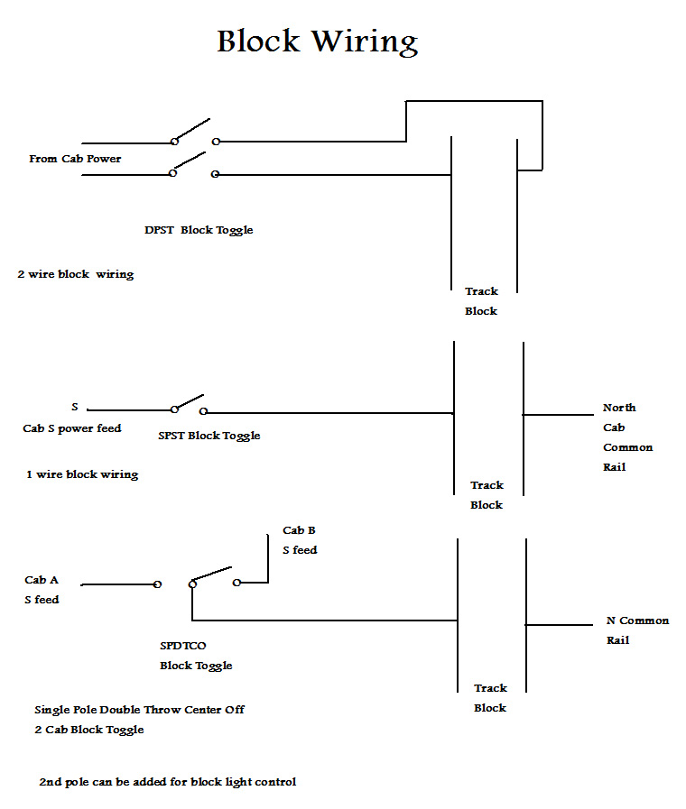
TRACK BLOCKS
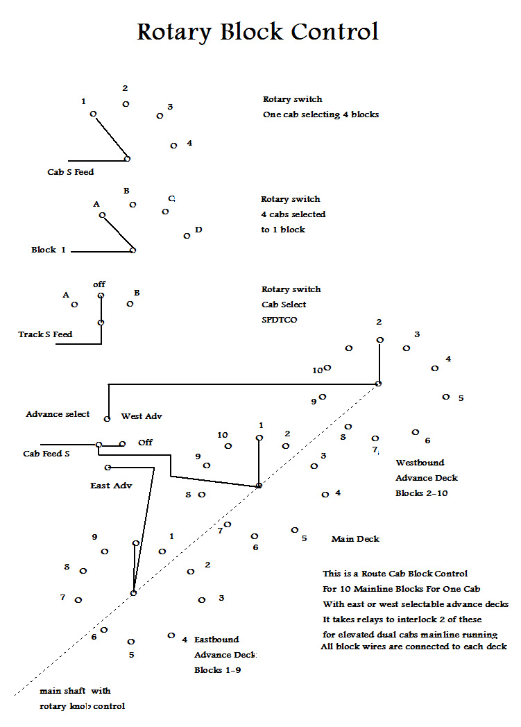
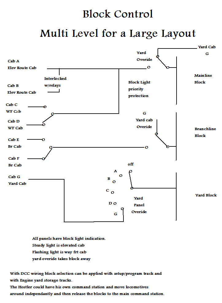
Track block wiring depends on the type of controls you are using. The old original 2 wire scheme with Double Pole toggles requires 2 wires (N & S) to each track block. The common rail (N) wiring system only rquires 1 wire (S) for each block from the panels. if you have duplicate panels for the same blocks then interlock wiring comes into play to protect each panel. 2 cabs in one panel is handled by SPDTCO toggles and automatically does the interlock for the 2 cabs. If your block switches are powering the block lights then they need to be Double pole swithes. If you have a small layout with one doulble cab panel the toggle switches indicate the cab selected by the postion of their handle. In this case no block light circuit is required. In larger layouts you get into rotary block switches and relay interlocks. This covers more than 2 cabs and more than 2 panels with the same blocks involved. With yard cabs you can wire a yard overide switch which works with a 2 cab panel besides the yard panel and gives the yard the control. This only works for yard master control on a larger layout. Of course with DCC all of this block control goes away except for the reversing sections which can be automated. With DCC then you need yard master control of the yard entry signals to protect the yard entrance.
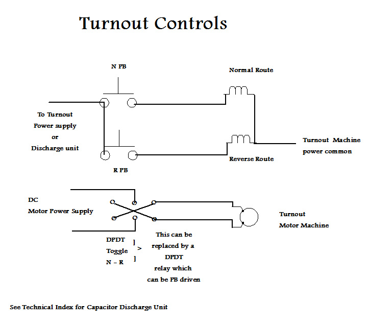
TURNOUTS
Turnouts are controlled either with manual throws or with electrical coil machines or motor machines. All throw mechanisms require electrical contacts to energize the frogs (and dead sections with DCC) as well as turnout indicator lights, signal systems, and any block selection. Relays added to the mechanism can handle the several circuits if required. It takes 1 pole per circuit to handle the job. Electrical coil (solenoid) type machines can be energized with discharge units which give them all the power they need and then shut off to protect the coils. When the button is released then the discharge unit recharges. The use of this discharge with diode matrix and therefore multi machines becomes more difficult. The multiple machines (2-8 at a time) draw higher current and there by power than when a single machine is selected. The first reaction is to raise the voltage to accomodate the multiple machines. This is damaging to the firing of a single machine and can destroy the machine. The answer is to not raise the voltage but increase the capacitor size to 4000, or up to 6000 mfd.This then releases the energy at the proper voltage and with the power that the machines require without a higher current than normal. Coil machines work with push button controls primarily (can be used with rotary selection switch and 1 button). The motor machines require a toggle switch which can reverse the polarity to make them reverse the throw on the turnout. A DPDT relay can do this with push button drive to energize the relay. This then allows the motor machines to run with push button control and diode matrix logic. Motor machines with relay control can be mixed with coil machines in the same diode matrix running the relays off the same discharge unit. The DCC control logic can run motor machines if the control units have DPDT functions.
BLOCK LIGHTS
Block lights are used on panels to indicate the assignment of blocks to cabs. The lights can be GOW bulbs or LEDs. For GOW bulbs the circuit normally is 10-12v. For LEDs a 1.5 v regulated power supply is the best solution. All block selection by toggle, rotary or relay switches. An extra pole on all these devices handles the block light circuits. The wiring network is very close to the track network that these devices control. When a block light is staedy on the mainline then a mainline cab has it. When the light is flashing then a Way Freight Cab has it. In areas of over ride the light will be steady when overiden by a yard cab selection.
©
Enjoy Model Railroading
Bill Ackland MMR


