


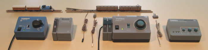
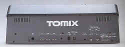
| This page illustrates and describes the Tomix "Neo" system of control and wiring items produced as of 2011. Controls and cords for turntables, working railway signals and so on are generally not included. The years of production are listed to the best of my abilities and information sources. | |
| Click here to see images and descriptions of earlier, retired control systems and items dating back to 1976, including the "original" and "NECST" systems. | |
| Click here to see images and descriptions of Tomytec control items. | |
Neo Control Series (1997-Present) |
|
| The current Neo line, at first called "NECST Neo", was introduced in 1997. It is generally identified by light blue cases with rounded edges. The Neo line uses an improved wiring system with small connectors at both ends of the cords (no more bare wire ends and push-release terminals). Therefore the Neo items are not directly compatible in connections with the earlier original and NECST systems. Further, the various connectors for DC track, the new 2-wire DC electric points/turnouts, and TCS (Terminal Connector System of sensors and controls for railway signals, level road crossings, automation and so on) differ in both configuration and color, so that they cannot be accidentally cross-connected. White connectors are used for track power and black connectors for accessories. The Neo generation of controls and cords are identified by the same "N" logo as NECST, but with "Neo" instead of "NECST" below it, on the packaging and larger units. | |
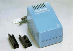 |
5500 Converter Box (1999-Present) - converts earlier original and NECST power output to the 12 VDC Neo 2-wire points/turnout control system. The Neo control boxes plug together in a stack into the left side of this converter, just as they can do on most Neo power units. This unit has both green and brown cables to receive power from various earlier pre-Neo systems. It makes the cabling conversion and rectifies AC to DC. Plastic clips are provided to hold it to the side of the earlier power units. |
 |
5503 Power Unit N-ES (1999-Present) - Input: 100 VAC 50-60 Hz. Output: 0-12 VDC (five-position dial, forward/off/reverse slide switch). This unit is a low-cost "starter" power unit with limited control capabilities, designed for Thomas the Tank Engine sets. It has an on/off rocker switch and a power/fault indicator LED. It lacks a power output connection for points/turnout control boxes. |
 |
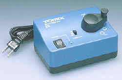
5504 Power Unit N-1 (2001-Present) - Input: 100 VAC 50-60 Hz. Outputs: 0-12 VDC 0.5 A (lever-handle control, forward/off/reverse slide switch); 12 VDC on left side for stackable control boxes. This basic power unit features an on/off rocker switch and a power/fault indicator LED. It has a tan case instead of the normal Neo blue. |
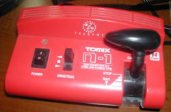 |
This special version of the N-1 power unit in a red case was manufactured as part of the Tomix Tsubame starter set, to match the coloration of the train. |
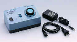 |
5506 Power Unit N-1001-CL (2009-Present) - Input: 100 VAC 50-60 Hz. Outputs: 0-12 VDC 0.7 A (dial control, forward/off/reverse slide switch) with CL (constant lighting) outer ring adjustment dial; 12 VDC 0.2 A for TCS; 12 VDC 0.3 A on left side for stackable control boxes. This CL-equipped unit has an on/off rocker switch and a power/fault (green/red) indicator LED. Replaced the 5502. Unlike its predecessor, this unit has an external cord-mounted power supply. |
  |
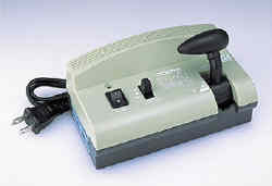
5511 N-DU201-CL Power Unit and 5512/5513 N-DU202-CL Power Unit (1999-Present) - Input: 100 VAC 50-60 Hz. (5513 is 230 VAC input). Outputs: two 0-12 DC outputs with separate forward/off/reverse slide switches, total 1.2 A capacity with CL constant lighting; 12 VDC for TCS; 12 VDC on left side for stackable points/turnout control boxes. This is a Neo-generation two-handle power unit replicating a real electric train cab control. Like the earlier 5016 DU-1, it has four controller power positions, with small dials to adjust simulated momentum on acceleration and coasting. It has five braking positions including emergency (immediate stop). The unit also has an on/off rocker switch, power indicator LED and green/yellow/red (power/coast/stop) indicators. Either green case (5511) or turquoise (5512 and 5513). |
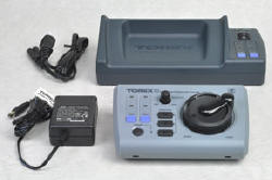 |
5514 TCS Wireless Power Unit N-WL10-CL (2010-Present) - This wireless power unit consists of a base cradle unit and a handheld wireless unit. Its inputs and outputs replicate those of the 5506, adding control of two turnouts/points (with LED indication) from either the base or wireless units. The wireless signals can be selected from 16 available channels (not infrared). The wireless unit requires 4 AA batteries. The unit packaging contains a "Use only in Japan" notation. The 5514 version is grey. |
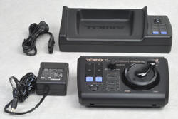 |
5515 TCS Wireless Power Unit N-WL10-CL (2010-Present) - This wireless power unit consists of a base cradle unit and a handheld wireless unit. Its inputs and outputs replicate those of the 5506, adding control of two turnouts/points (with LED indication) from either the base or wireless units. The wireless signals can be selected from 16 available channels (not infrared). The wireless unit requires 4 AA batteries. The unit packaging contains a "Use only in Japan" notation. The 5515 version is black. |
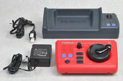 |
5516 TCS Wireless Power Unit N-WL10-CL (2010-Present) - This wireless power unit consists of a base cradle unit and a handheld wireless unit. Its inputs and outputs replicate those of the 5506, adding control of two turnouts/points (with LED indication) from either the base or wireless units. The wireless signals can be selected from 16 available channels (not infrared). The wireless unit requires 4 AA batteries. The unit packaging contains a "Use only in Japan" notation. The 5516 version is red. |
|
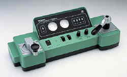
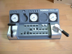
5521 N-S2-CL TCS Power & Sound Unit (2002-Present) - Input: separate 100 VAC 50-60 Hz power supply. Output: two 0-12 VDC outputs with forward/off/reverse toggle switches, total 1.6 A capacity with CL constant lighting; 12 VDC for TCS; 12 VDC on left side for stackable points/turnout control boxes. This is the top-of-line simulated control stand with power control lever, brake handle, voltmeter ("speedometer"), ammeter, simulated air brake pressure meter, and so on. Plus it adds sound effects including door closing, actual prototype horns (with foot pedal actuation), tunnel effect, bridge effect, crossing sounds, flange squeal, station announcement, etc., using the built-in speaker or headphones. There is even a recessed round area for the engineer to place his personal pocket watch for time-keeping. Sounds can be activated manually or using TCS sensors on the track. Charcoal grey case. |
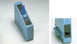 |
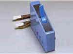
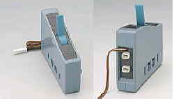
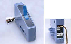
5531 Point Control Box N-S (1999-Present) - This control box attaches to the left side of most Neo power units, making electrical input connections at the same time. It has a single output receptacle and controls a single 2-wire DC-powered points/turnout. |
 |
5532 Point Control Box N-W (1999-Present) - This is similar to the 5531 above, but has two output receptacles and controls a pair of DC-powered track points/turnouts. It is useful for a double-ended siding, crossover, double-crossover and so on. (Note: With the older control boxes, you could simply insert two or more bare wire ends at once into each push-release terminal to control multiple AC-powered points.) |
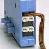 |
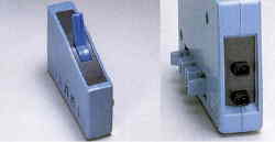
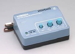
5533 Universal Switch Box (1999-Present) - This control box has two track power input cables and four output cable receptacles (two switched and two unswitched). It is used to manage two power inputs going to tracks at double-crossovers, and to simplify wiring and operation of return loops with reverse-polarity issues. Its instruction sheet illustrates these uses. A joiner piece is included that covers and connects an adjacent control box toggle handle so that points/turnouts and the reversing function can be switched together (see image at top of page). It and the other Neo track power control boxes listed below still require daisy-chaining of their cables to the power unit, as in the earlier control series, but with connectors replacing bare wire ends. |
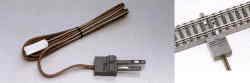 |
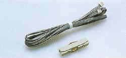
5534 DC Feeder N (1997-Present) - This version of the Tomix DC feeder track connector has a Neo-style connector at the power unit end and a permanently-connected two-prong track clip, cast in grey plastic, at the track end. |
 |
5535 Reverse Switch Box (2004-Present) - This control box is used to separately reverse polarity of a track section, such as a return loop, reversing wye and so on. It has a Neo track power input cord and two output receptacles (switched and unswitched). |
 |
5536 Selector Switch Box (2004-Present) - This control box has a Neo track power input cord and receptacles and two track outputs. It turns one or the other track outputs on, but I do not believe it provides a "both on" or a "both off" capability. |
 |
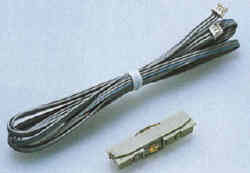
5537 DC Feeder N for Slab Rail (2006-Present) - This track power connection cable clips to the underside of Slab Rail track pieces. |
 |
5538 DC Feeder N for Wide Rail and Slab Rail (2009-Present) - Similar to the above clip, but also fastens to the underside of Wide Rail. |
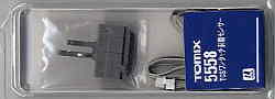 |
5558 TCS Sensor (Plug-in) (2002-Present) - This is the original track sensor for regular Fine Track. It inserts into any opening in the roadbed that the DC Feeder N would fit. The long prong slopes upward slightly, so the passing wheel flanges contact it. |
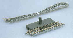 |
5559 TCS Track with Sensor (set of 2) (2007-Present) - This version of the TCS sensor is pre-assembled into an S70 straight track piece, with a side platform housing a small circuit and a TCS receptacle at each end. |
 |
5563 Automatic Operation Unit (2005-Present) - A TCS-based controller that can provide nine different automated train operations, plus allows manual operation. Patterns include back and forth, back and forth with intermediate stop, zigzag through points/switchwork ("Z"-shaped crossover or "X"-shaped double-crossover pattern), terminal-to-point rotating among three trains, oval with station stop, oval with alternating trains (in same direction and in opposite direction), and oval with random stops and direction changes. The unit provides adjustment dials for stop duration and acceleration/deceleration momentum. |
 |
5566 TCS Sensor for Slab Rail (2007-Present) - When Tomix introduced its Slab Rail, track with the appearance of being set in a concrete base, this sensor variation was needed to provide the TCS sensing function. |
 |
5567 TCS Sensor for Wide Rail and Slab Rail (2009-Present) - Similar to the earlier 5566 above, but this one also works with the later Wide Rail track type. |
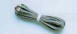 |
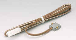
5811 Extension Cord for TCS Sensor (1999-Present) - A three-wire 250 cm long gray cable with small white connectors at each end. It is not really an extension cord (plug to receptacle), just a longer cord (plug to plug). |
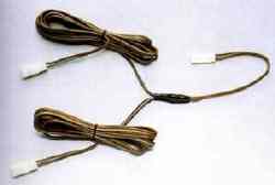 |
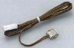
5812 Divergence Cord for DC Feeder (1999-Present) - A 1.5 meter extension cord with white Neo connectors that splits to feed two DC Feeder cords. (Note: With the earlier systems you could just insert two bare wire ends into each push-release terminal.) |
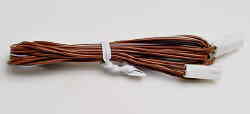 |
5813 Extension Cord for DC Feeder (1999-Present) - A 1.5 meter extension cord for track power with white Neo connectors at both ends. |
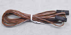 |
5814 Extension Cord for Points (1999-Present) - A 1.5 meter extension cord for points/turnout leads with black Neo connectors at both ends. |
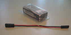 |
5817 Cross Cord for Electric Points (2003-Present) - A short red/black cord that flips the points/turnout leads to reverse which way the points throw. This is needed in certain cases because the connectors are polarized and can not be flipped to reverse them. |
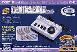 |
Power Unit N-400 (2007-Present) - Input: 100 VAC 50-60 Hz. Output: 0-8.5 VDC 0.4 A (dial control, forward/off/reverse slide switch). This unit is only sold in the 90093 Model Railway Operation Set (Mini Curved Tracks). It has no power output connection for points/turnout control boxes; instead, it has two built-in point/turnout control toggles with output receptacles at the rear of the case. It also features an on/off rocker switch, a power indicator LED and (this is surprisingly unusual) Japanese control lettering. Light grey case. |
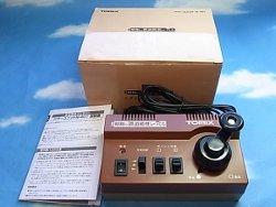 |
Power Unit N-401 (year unknown) - This unit is like the set-only N-400, but has a brown case and a fancier control dial with a handle on it. It apparently was manufactured to be part of a Kodansha project railway layout kit. |


