 |
Steam Locomotion in the 21st Century The Recent History of Steam Locomotive Development |
Updated 4 February 2022
| One of the most
important components of virtually all steam locomotives is
the exhaust system. Early steam locomotive builders such
as George Stephenson discovered the principal upon which
virtually all steam locomotives built since have used. By
happy accident, they found that directing the "waste"
steam exhausted from the cylinders at the end of each
stroke up the boiler's chimney greatly increased the air
flow through the fire. This caused the fire to burn hotter
and faster, allowing a locomotive boiler to generate
dramatically more steam than stationary boilers of similar
size.
As locomotive design progressed, builders realized that the proportions and configurations of the chimney and the exhaust pipe had a significant effect on how well the exhaust system worked. A major concern was the effect of backpressure on the performance of the locomotive's cylinders. Backpressure was a measure of the restriction of the exhaust steam flow from the cylinders at the end of each stroke. The locomotive exhaust could be built with a small exhaust nozzle, which caused the exhaust steam to jet up the stack at high velocity, which would produce excellent gas flow through the boiler (draft). However, this small nozzle would impede the flow of the exhaust steam from the cylinders, causing excessive backpressure. This backpressure saps power from the locomotive's cylinders, reducing the locomotive's performance. Good draft increased the locomotive's steaming rate making more steam available to generate power, but high backpressure could cancel this out. This was the chief task of locomotive exhaust designers: how to produce the maximum draft while producing the minimum back-pressure on the cylinders. Until well into the 20th century, the physics of gas
flow were not understood and the theories and laws which
could be used to design exhaust systems did not exist.
Consequently, for much of their existence, locomotive
exhaust systems were developed through a process of
trial-and-error. Chapelon, Porta, and others strove to
apply principals of engineering and physics to exhaust
system design. |
|
 |
This exhaust system, from a locomotive in New Zealand, is similar to that of many 19th Century locomotive exhaust systems. The steam nozzle is at the bottom, and it exhausts through a "petticoat" and finally up through the main chimney (the separate petticoat was a 20th century development). This chimney includes a spark arresting apparatus, which forces the exhaust gases through several turns in order to make sparks and cinders drop out into the bottom of the spark arrestor. |
 |
This drawing shows a typical locomotive
exhaust system from a U.S. steam locomotive built in the
20th century. The drawing shows a cross-section of the
smoke box at the front of a locomotive boiler (the boiler
would be to the left of the view). The steam nozzle is at
the bottom of the smoke box, exhausting its steam jet up
the stack which is at the top. The drawing also
illustrates the empirical design formulas which were used
to size the components. After building hundreds of exhaust
systems, designers decided that the proportions of the
components listed above would work best for most
locomotives under most conditions. |
 |
This drawing shows an early Kylchap exhaust. Chapelon used the exhaust splitter developed by Finish engineer Kylala, which divides the exhaust stream into four parts. The Kylchap draws in gases from more than one level of the smokebox, which Chapelon believed to be an important feature in providing an even gas flow through the many tubes of the boiler. Later Kylchap exhausts used two levels of entrainment and two or even three stacks. |
 |
The Kylala exhaust splitter was an important part of the Kylchap exhaust system. |
 |
In the U.S., several railways developed improved exhaust systems using annular exhaust nozzles and larger stacks. |
 |
Plan view of the so-called "waffle iron"
exhaust nozzle used in the exhaust system shown above. |
 |
The Lemaitre Exhaust was developed by
Lemaitre, a mechanical engineer from the NORD Belge in
France. The Lemaitre featured 5 nozzles in a circular
pattern exhausting up a large diameter stack, with a
variable area nozzle exhausting up the center. British engineer Bullied used a simplified version of this on the locomotives he built, omitting the variable area center nozzle. |
|
|
In the late 1940's, Dr. Adolph
Giesl-Gieslingen developed a new exhaust design called the
Giesl Ejector. He patented this device and it was applied
to thousands of steam locomotives all over the world. The
Giesl Ejector featured a series of small in-line nozzles
exhausting up a thin, oblong chimney. This system was patented and produced under license, and was applied to many steam locomotives around the world in the 1950's, and 1960's, giving improved performance and fuel economy. Unlicensed copies of these exhausts were also produced and applied to some locomotives in China. drawing courtesy Stuart Kean |
 |
This diagram shows the Lempor (Lemaitre-Porta) exhaust developed by Porta and applied to many locomotives. Porta also developed an extensive theory describing the performance and design of these exhaust systems. |
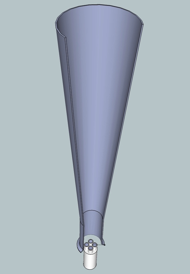 |
Here is a 3-D rendering of a Lempor
ejector. The picture shows the full exhaust system with a section taken out of the stack to show the inside. The system shown uses the revised design developed by Porta with a non-tapered mixing chamber (the lower portion of the stack) and a 10 degree angle between the nozzles, as experimentally determined to be optimum by Wardale. |
 |
One of the most recent new exhaust systems was developed for the Garratt locomotives of the Rhodesian Railways. These were known as "pepperpot" exhausts and were later fitted to many Garratts which were overhauled and restored to service in the early 1980's in the new country of Zimbabwe. This nozzle arrangement was used in combination with a larger chimney, and was developed as alternative to Giesl exhausts experimentally fitted to Garratts in the 1960's. The pepperpot exhaust was preferred because (1) it was locally developed (the Giesl was proprietary and royalties had to be paid for its use) and (2) the Pepperpot was less susceptible to unauthorized tampering which tended to cause problems with the Giesls in normal service. |
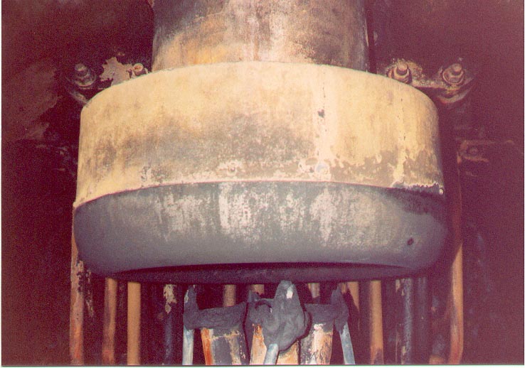 |
For the last years of his life, Porta
worked on the development of a Lemprex exhaust
system, a further advancement on the Lempor. The Lemprex
incorporates features to maximize its performance within
the limited height available on a steam locomotive. This
photo shows one of the last exhaust systems installed
under Porta's supervision, on the Donna Teresa Christina
Railway in Brazil. This exhaust incorporates at least some
features intended for the Lemprex, namely the skewed
exhaust and blower nozzles which were to give a swirling
motion to the exhaust gases as they passed out of the
stack for improved mixing and performance. |
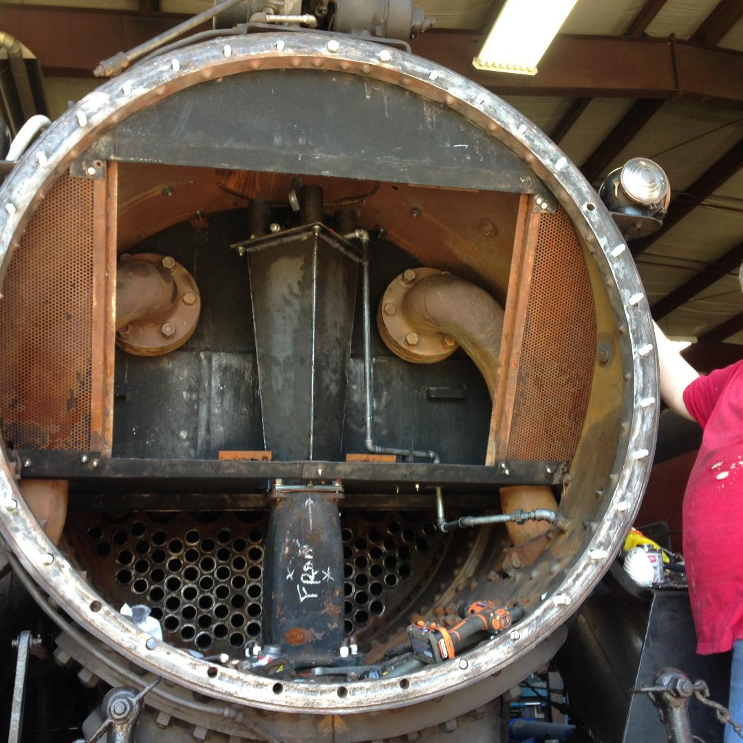 |
Some of the most recent exhaust
development work was carried out by Dr. Jos Koopmans of
the Netherlands, who wrote his doctoral thesis on exhaust
systems some years ago, later published as the book "The
Fire Burns Much Better". In early 2018, Waterloo Central Railway 0-6-0 No. 9, formerly Essex Terminal No. 9, was fitted with a multiple jet exhaust system designed by Dr. Jos Koopmans and fabricated by steam enthusiast Michael Guy. This system made use of the existing, relatively short chimney, and omitted the two separate petticoats provided in the original exhaust system. A new extension raises the nozzle assembly so that the nozzles are correctly aligned with the existing stack. Performance with this system has been significantly increased over the original exhaust. In 2016, Dr. Koopmans installed a similar system in the UK on King Edward II 4-6-0 No. 6023. This system successfully restored the locomotive's performance after the stack (chimney) height had to be reduced by 4 inches to meet new clearance requirements. Photo courtesy of Michael Guy. |
Back to Top |
Return to the Exhaust Systems Page |