 |
Steam Locomotion in the 21st Century The Recent History of Steam Locomotive Development |
photos and descriptions by Shaun McMahon, March
2000
Updated 8 February 2022
The following photos illustrate the Kylpor
(Kylala-Porta) exhaust system as fitted to the 2-10-2 "Santa Fe"
locomotives of the Rio Turbio line in southern Argentina. Sadly,
these locomotives were displaced by imported diesels and most now
lay derelict in Patagonia.
|
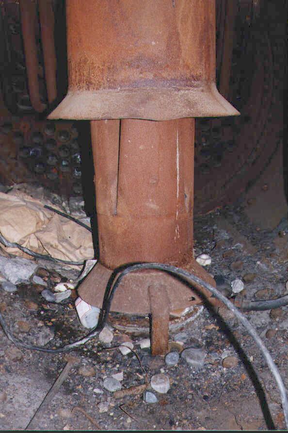
Photo Number 1 The Kylpor exhaust system in position, developed from the Kylchap Exhaust and superceded by the Lempor Exhaust. The mixing chamber with tapered entrance appears at the top of the photo; the Kylala exhaust splitter with its own tapered entrance at the bottom and four "splitter" sections at the top is shown below.
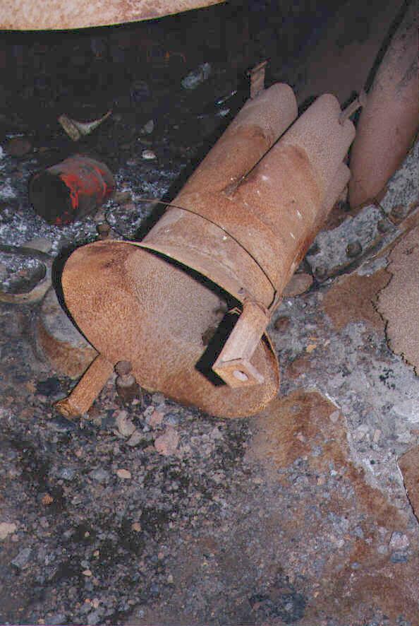
Photo Number 2 Kylpor exhaust manifold in partly disassembled stated inside one of the Rio Turbio 2-10-2's at Rio Gallegos. Note the mounting brackets at the bottom of the manifold and the spacing lugs protruding from each lobe. The latter guaranteeing lining up accuracy and ease of obtaining same. This method is not used in practical terms to line up the Lempor Exhaust. NOrmally, the French method is used using a contact indicator rotating on a base mounted to the blast pipe base flange- tolerance of 1 mm.
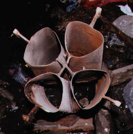
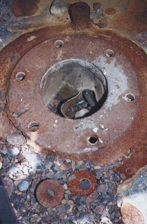
Photo No. 3 Looking down into the Kylpor exhaust splitter of one of the Rio Turbio 2-10-2's. This view clearly shows the gradual divergence of the lobes and the "egg" shape of the lobe interiors. A comparison of these photos with recent photos of the Lempor exhaust system shows how Porta very cleverly reduced the Kylpor to produce the Lempor, in terms of component size, single stage mixing, and ease of manufacture.
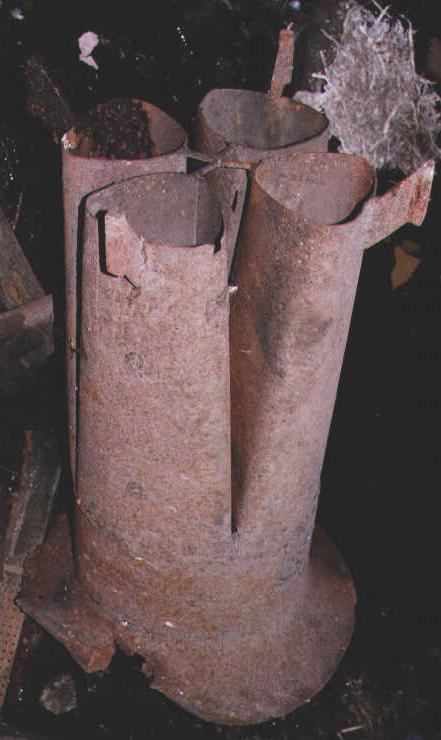
Photo No. 4 Elevation view of Kylpor exhaust splitter in one of the Rio Turbio Santa Fe class 2-10-2's.
Photo Number 5 Curved Kordina dividing wall as fitted to Rio Turbio 2-10-2.
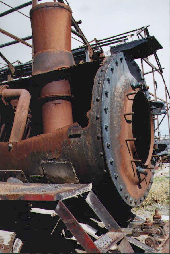
Photo No. 6 The smokebox of this Rio Turbio 2-10-2 has been cut away and in this state one can see the mounting of the Kylpor mixing chamber (straight section) and diffuser (tapered section at top). Note the conical mounting section fixed to the outer smokebox which not only provides rigidity but also a fixed distance for draughting purposes allied with details as shown in picture number 2. |