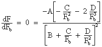
Fig 1 The Lempor Ejector
The principal parts of the ejector are (Fig 1)
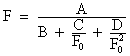
| A. | The blast pipe or tuyère made up of four nozzles with converging-diverging sections so as to account for the supersonic flow prevailing during the exhaust beats. |
| B. | The mixing chamber of slightly converging section whose length is a compromise between the evening-out of exit velocity and available total height. |
| C. | The diffuser, having the maximum possible diverging angle, yet with good diffusing efficiency. |
| D. | The Kordina, which is really an ejector in itself disposed so that each steam puff creates a vacuum in the other cylinder. |
The interesting cross-sections are:
| Symbol | Units | Description |
| Fs | [m2] | The chimney exit area |
| F1 | [m2] | Chimney throat area |
| Fb | [m2] | Gas inlet area at the bottom of the mixing chamber |
| F | [m2] | Steam tuyère area |
| F0 | [m2] | Ideal diffuser outlet area |
Let also be:
| L | [kg s-1] | Gas mass (rate) to be expelled |
| D | [kg s-1] | Mass rate of steam flowing through the tuyère |
| W0 | [m s-1] | Mixture velocity at ideal outlet |
| W1 | [m s-1] | Mixture velocity at chimney throat |
| Wb | [m s-1] | Gas velocity at gas inlet section of area Fb |
| W | [m s-1] | Gas velocity at tuyère exit plane |
| px | [N m-2] | Static pressure (absolute) at the tuyère exit plane |
| p0 | [N m-2] | Atmospheric pressure |
| pc | [N m-2] | Smokebox pressure |
| p0 - pc | [N m-2] | Draught |
| p1 | [N m-2] | Pressure at chimney throat |
| v1 | [m3 kg-1] | Specific volume of the steam-gas mixture |
| x | - | Coefficient expressing the pressure drop due to friction in the mixing chamber |
| x b | - | Coefficient expressing the pressure drop at the gas entrance |
| l | - |  |
| F0 | [m2] | Ideal diffuser outlet
section =  |
| h | - | Diffuser efficiency (e.g. 10) |
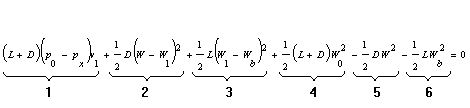
Assuming a uniform velocity distribution at every cross-section, the fundamental equation of the ejector is obtained by applying the principle of the conservation of energy to the fluid streams:
In this energy balance, there are 6 terms:
| 1- | Mixture compression work which is considered to be carried out at constant specific volume v1 and from the pressure prevailing at the tuyère exit plane |
| 2 & 3- | Shock losses obtaining in the mixing chamber |
| 4- | Loss by kinetic energy of the gas having a non zero velocity at the ejector outlet. The outlet section is taken smaller than the actual one so as to account for energy losses within the diffuser. |
| 5- | Useful steam energy |
| 6- | Useful gas energy |
Later a correcting term will be incorporateed to account for the friction obtaining in the mixing chamber.
Expanding Equation 1, simplifying and dividing by 2 (L+D) and grouping the quadratic terms, we have:
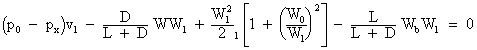
The continuity equations can be written:
![]()
![]()
![]()
![]()
Introducing these values into Equation 2, operating and setting l as above,
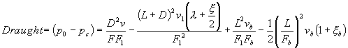
This expression gives the vacuum at the tuyère exit plane. But it is more convenient to work with the vacuum (pressure) prevailing in the smokebox, this related to the working requirements of the boiler. It is
![]()
Therefore it is
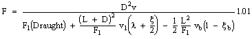
Introducing Equation 4 into Equation 3, the fundamental expression giving the smokebox draught is obtained:
At this point, the friction at the mixing
chamber and gas entrance are immediately introduced. x is a coefficient
introduced to express the pressure drop as a fraction of the
velocity head at the throat 1/2 ![]() and x b that corresponding to the gas entrance.
and x b that corresponding to the gas entrance.
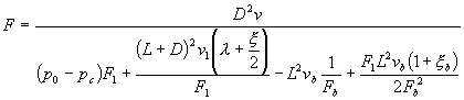
The whole of this treatment assumes that the problem is unidimensional, i.e. that the gas and steam streams are coaxial. Equation 5 can be easily solved numerically, giving arbitrary values to F1 and Fb and choosing the pair making F a maximum. While it is possible to operate mathematically the expression so as to have a formula giving F directly, the former procedure has the advantage of showing the sensitivity of the design to a change in the different variables.
It can be written:
Equation 6 can be written
|
Equation 7 |
in which ![]()
![]()
![]() since x b is small.
since x b is small.
The optimum Fb that makes a maximum of F is obtained by differentiating equation 7 and equating to zero.
It is
![]()
Hence
This result shows that the optimal mixing chamber is not a constant section one. If this result is introduced into Equation 5, we get
|
Equation 8 |
and
This equation can be solved graphically giving tentative values to F1 = Fb so as to get the maximum for a tuyère area giving the lowest back pressure.
This theory is based on Strahl’s theory (1) with convenient modifications. A numerical check against the application of the momentum theorem to the mixing chamber showed coincident results. Later, it was possible to demonstrate a rigorous equivalence.
The factor 1.01 accounts for a flow coefficient of 0.99 deduced experimentally from data taken at the Rugby test plant.
As a typical value for x , the figure of 0.10 can be taken, but a more exact estimation is possible if the theory given in (1) is accepted. x b » 0.04 can be considered a typical value for a carefully designed bell mouth.
Equation 5 allows the prediction of the performance of any ejector satisfying the assumptions stated before, while Equation 9 gives the optimum dimensions. It is clear that the design, or the prediction of performance, cannot have better accuracy than the boiler data on which are based L, D, draught, vb, etc. and also the steam conditions at the blast pipe tip. These can be forecasted with reasonable accuracy by means of laborious calculations, but undoubtedly actual test data are far more desirable. However, this is not enough: a locomotive ejector, the very heart of the machine, must incorporate due allowances for maintenance standards, fuel quality variations, service required from the locomotive, unavoidable steam and gas leaks, etc. Besides, it cannot be claimed that the present theory contemplates all the phenomena occurring in the ejector in full detail. Therefore it is to be used as the best available approach to an optimum, the final adjustment is to be carried out in practice by actual train running and fitting various tuyères of different area as it has been the universal practice since the days of George Stephenson. Fortunately, the main chimney dimensions are given by very flat curves and therefore it is possible to play within a fairly large latitude. To account for these phenomena, the ejector should be designed for 5% extra gas quantity and 10% more draught.
(1) 2VDI, 57 (1913), p. 1739
{Porta L.D., Heat transfer and friction in ejector mixing chambers, 1974}
The theory can take into account compressibility effects, which are actually influenced at the highest rate of working in engines operating with very high draught requirements (up to 700 mm H2O in the SNCF 141R (see Appendix A4). Calculations should be carried out solely for the maximum rating since experience shows that the automaticity of an ejector so designed is satisfactory and not giving too large an excess of air at low working, while- and as a matter of course- no front end limit is apparent.
The calculations are to be repeated if the engine is called upon the work at very high heights above sea level, the atmospheric pressure becoming much lower (53% of sea level pressure at 4775 m above sea level on the Tocompa (?) line, Argentina). As it is well known, combustion phenomena change appreciably, yet a very limited experience seems to indicate that the same ejector behaves satisfactorily with independence of the height. But this does not prove that the optimum dimensions for sea level working remain also optimum at higher heights.
The whole design is a compromise because of the limited height available. The mixing chamber and the diffuser dispute the space on hand, and therefore the tuyère should be placed at the lowest possible position in the smokebox. So far as the written experience is concerned involving the gas producer combustion system, no fears arise of "burning too much at the front or the back" as many time has been said, but no evidence has been produced.
When carrying out the computations, due allowance should be made to account for leakage steam not passing through the blast pipe, air leakage into the smokebox, stoker jets or burner steam (increasing the gas quantity to be sucked), stoker engine steam, oil heater steam, vacuum ejector steam, lighting generator steam, steam to ashpan for the gas producer combustion system, etc. which are far from being negligible.
Another point to be considered is the one concerning building up inaccuracies whose influence can in no case be favouring, and therefore the actual design should incorporate all available means to provide adequate lining up and also least perturbations in the flow.
An allowance of 1% extra section should be considered on the value of F to account for the contraction coefficient.
Finally, last but not least, nothing is known about the influence of pulsating conditions obtaining in locomotives. So far, ejectors designed on the steady flow hypothesis have behaved satisfactorily and blast pipe area so predicted required little adjustment in practice and within ±5%.
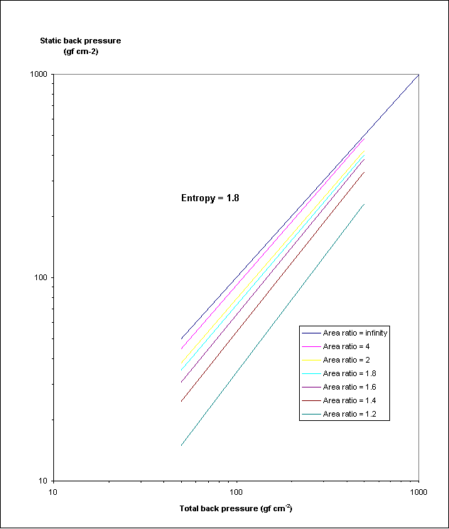
Fig 2: Relation between static and total back pressure
Comparative measures of ejector performance
Since most locomotives operate with similar relations between gas and steam mass (L/D » 2) and all of them have high superheat temperature and not too different internal cylinder efficiency, the gas and steam conditions do not differ too much. Therefore the usual back pressure - draught curve is a fair measure of ejector efficiency. The application of thermodynamic principles lead to consider the total back pressure which can either be measured with a Pitot tube in the exhaust stand (at ¾ radius of the tube) or corrected according to the graph given in Fig 2 if the static pressure has been measured.
Fig 3 gives comparative curves. Those reported to be ejectors designed by the author refer to Kylpor ejectors built some 15 years ago and therefore giving a somewhat worse performance of what could be expected from a today’s design. It is seen that performance is some 40% better than any other type of apparatus, possibly increasing to 50% if the present knowledge is applied.
Another comparative parameter, easier to determine, is the relation given in Table 1.
![]()
The back pressure is proportional to the (tuyère area)2 while the boiler draught is proportional to (gas area)-2. Due allowance should be made when comparing ejectors, to the fact that oil-burning and "gas producer" engines are so designed that part of the steam produced does not pass through the blast pipe.

Fig 3 Comparative performance curves.
Table 1
| Engine | Tuyère area F cm2 |
Gas area W cm2 |
F/W |
(F/W )2 •104 |
Ejector |
Fuel |
| PO240.701 | 200 |
4942 |
0.0405 |
16.4 |
Kylchap |
Coal |
| 242A1 | 246 |
5593 |
0.044 |
19.3 |
Kylchap |
Coal |
| 141R | 179 |
5091 |
0.035 |
12.4 |
Kylchap |
Fuel oil |
| 141R | 179 |
5910 |
Kylchap |
|||
| 141R | 229 |
5910 |
0.039 |
15.0 |
Kylchap |
Coal |
| 141R469 | 199 |
5910 |
0.034 |
11.3 |
American |
Coal |
| 9F | 195 |
5091 |
0.035 |
14.7 |
Giesl |
Good coal |
| 1802-FC6B Argentine | 216 |
5000 |
0.043 |
18.0 |
Improved existing Kylchap |
Oil burning |
| 4674FC6B Argentine | 110 |
2078 |
0.054 |
29.0 |
Kylpor |
Gas producer combustion system, high ash coal |
| 4674FC6B Argentine | 115 |
2078 |
0.057 |
32.0 |
Kylpor |
Gas producer combustion system, high ash coal |
The back pressure
One of the ultimate goals of ejector design is to make a least demand to the engine in terms of back pressure or either to produce the maximum draught with a given back pressure. High draught produced economically means ample latitude to play with boiler design, gas areas, grate design, etc. essentially resulting in a smaller and lighter boiler, dispensing extra carrying wheels, good turbulence in the firebox, clean tubes, less smoke and happy crews because of an adequate steaming reserve. No effort should be spared in designing the ejector for maximum efficiency, otherwise one would fall into the trap of the "good enough engineering" which would come short of the hard competition obtaining in a near future.
The meaning of the back pressure goes further than the simple horsepower evaluation obtained after introducing its figure in the IHP formula: it is the lower boundary of the steam cycle and its importance can be clearly shown when comparing its heat drop and the engine heat drop on the Mollier and of course its value is sensible at high powers and reduced cut-off.
Back pressure is usually measured with a manometer connected to the exhaust stand, but this is thermodynamically not correct because solely the static back pressure is reported: no account is given to the energy of the steam at the measuring point which is extracted from the pistons. Figure 2 gives the proper correction factor, which is not great in usual circumstances, but not so when the area ratio of stand pipe/tuyère is near unity. This happens especially in improved engines, not to say in author’s designs in which the exhaust stand area equals the tuyère area: the static pressure manometer always reads zero.
The normal design of the exhaust stand is such that each puff of one cylinder affects the piston on the other and therefore the time average back pressure, static or Pitot, is reflected in the indicator diagram. In the author’s designs the exhaust stand is so designed that the indicator line shows a lower back pressure than the manometer reading.
The time average back pressure can be obtained from the Mollier after an allowance for a flow coefficient of 0.99 which has been deduced from test data obtained at Rugby. This coefficient accounts for the actual reduction resulting from friction in the tuyère, the pulsating nature of the flow, the supersonic puffs, etc. One allowance should be made on the pressure around the tuyère, which is lower than the atmospheric.
Final comments
The theory here presented involves an accurate mechanical realization which is somewhat difficult given the kind of apparatus working in a hostile environment and handled by usually rough boilersmiths. It is felt that there is room for improvement and development work, particularly in considering the effect of pulsations.
Since the back pressure - draught experimental curves show a definite progress which it is hoped to still improve, it is felt that this will lead to a reduction of the boiler size for a given heat duty, therefore making a contribution to the increase of the power to weight ratio.
The present paper is a draught for a book (in preparation) to be entitled "Modern Steam Locomotive Engineering".