Converting an american Flyer engine to run with 2.4 Ghz radio control
By Doug Stoll
Converting Locos to Operate on
2.4 Ghz radio Control while
Recharging on Track
American Flyer "Zombie Rail"
Zombie rail is basically Dead Rail with charging from track while operating. The combination of the two allows flawless operation of the locomotive though dead spots in the rail. RC 2.4 ghz control also allows the direct directional change of the loco and operation of accessories with hand held pendant or Spectrum radio control transmitter used for RC planes and helicopters which I have as a second hobby.
The operational description is located on Zombie Rail page.
Alternatives transmitter and systems are for model railroads only and are for sale from Revoelectroics that may work with some hardware below and are rated for 5 amps with a peak load of 8 amps which is within parameters of American Flyer. Complete system setup and programming for this option is available from Garden railway club called OVGRS.
Tools and components required are listed below.
I also have created a Facebook group called American Flyer Zombie Rail. Reasoning is the upgrade is not entirely Dead Rail. Facebook location online is American Flyer Zombie Rail | Facebook.
Tools Needed:
Soldering Equipment
Solder for electronics (rosin core and medium or light duty recommended. I have had issues with overheating components using HD solder)
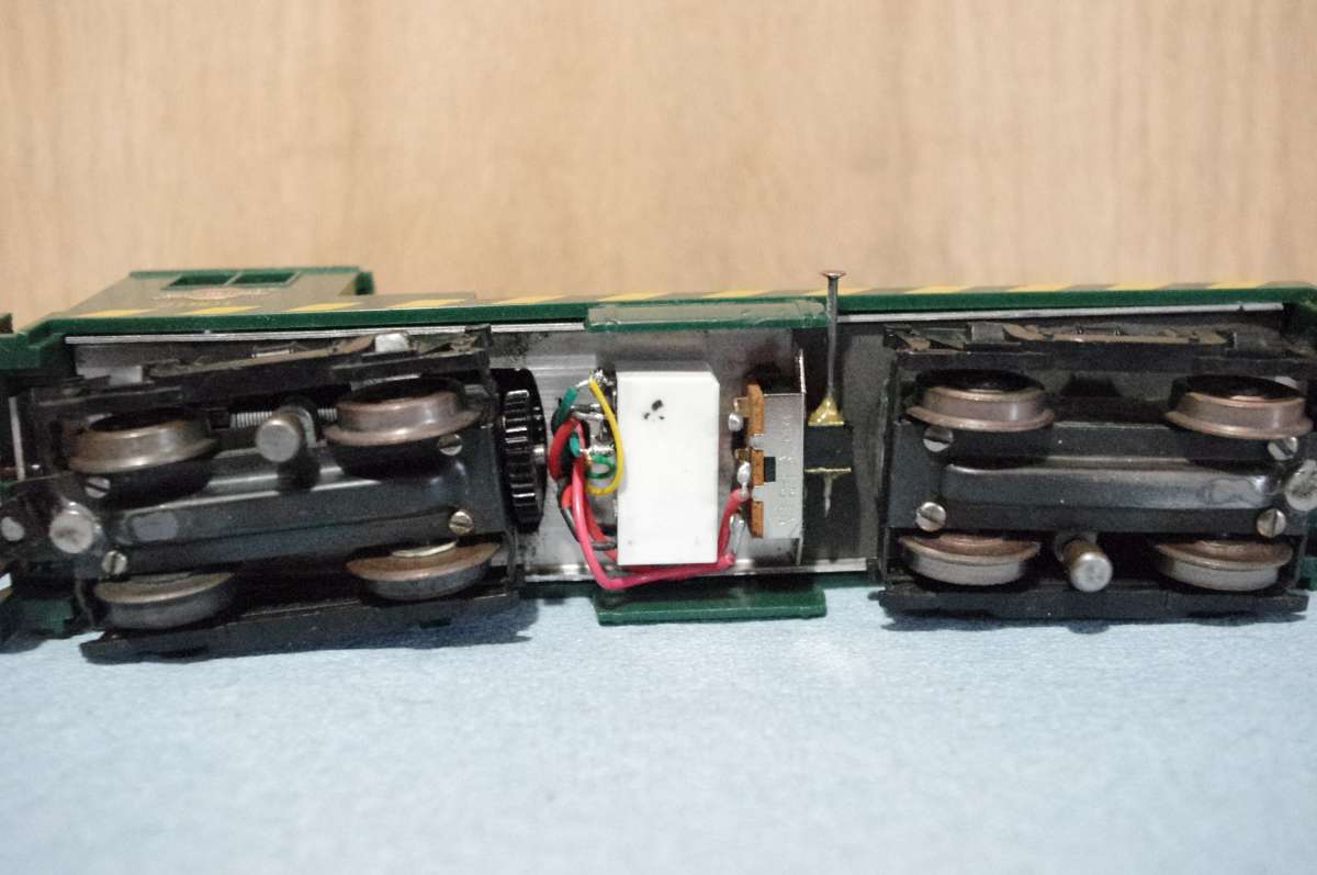
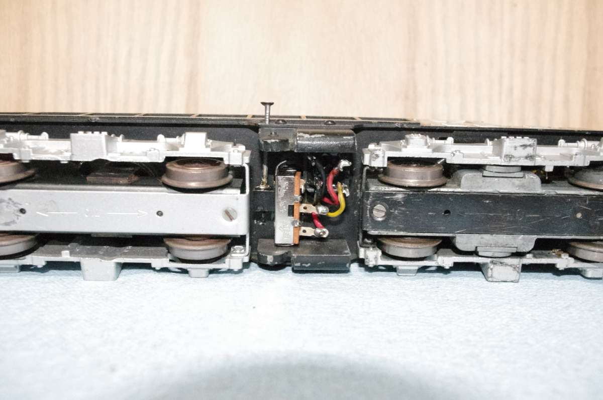
The information below reflects both the diesel and steam set-ups. Battery size and location of the hardware may be different, but hardware is the same or similar.
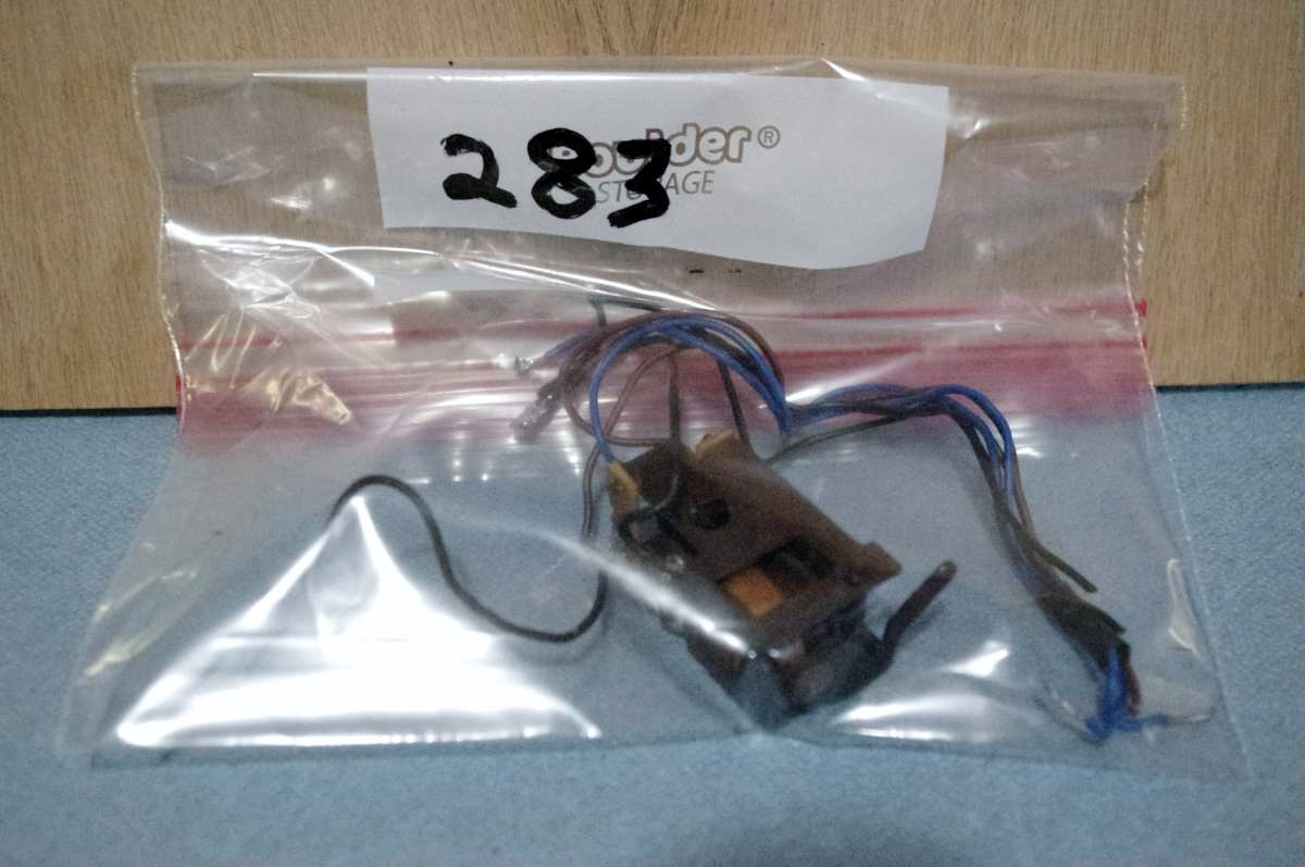
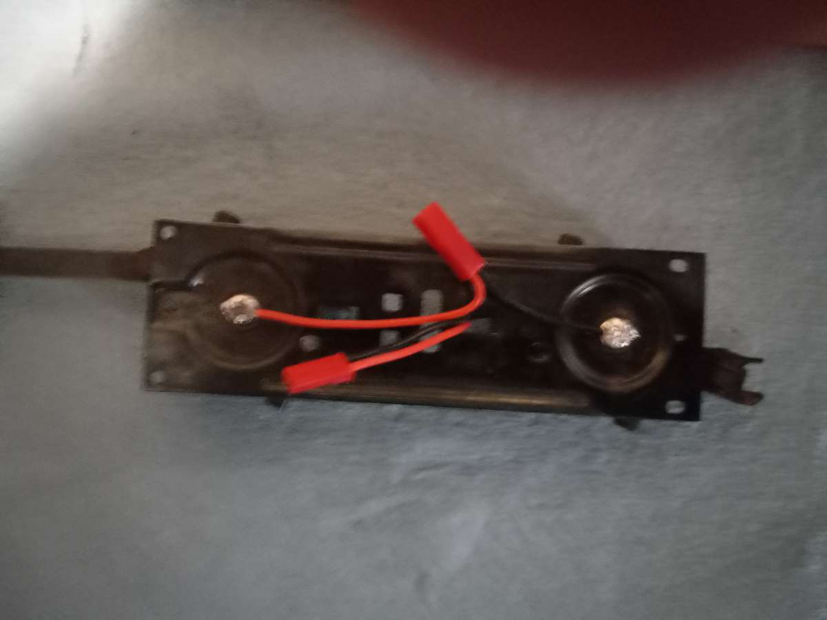
Separate engine from tender at drawbar. Disconnect (unsolder) E-unit wires from loco and truck rivets on tender frame. Remove E-unit from tender. Place E-unit, screw, and wiring intact into bag. Write on bag which loco it came from, so it can be returned. May wish to take pictures or label wires with masking tape. example would be front tender pick-up (FT) and Back Tender Pick-up (BT), Left and right field (LF)(RF), left and right brush (LB)(RB), etc. If you choose to make your tender shell disconnect capable, solder JST connectors to the rivets making sure the surface of the rivet solder is not pointed that could puncture a component.
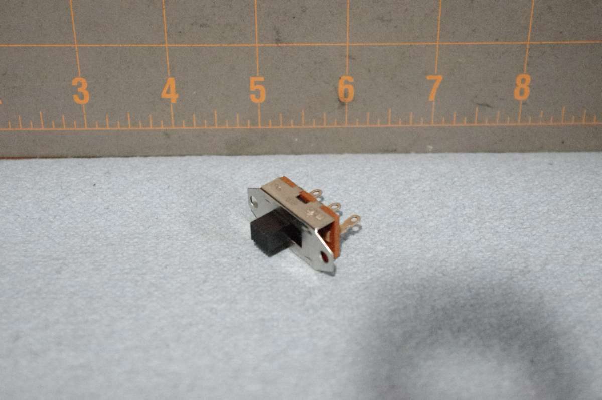
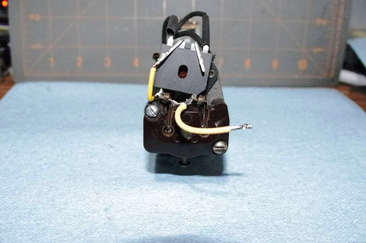
The next step is installation of activation switch. If you plan on changing transmitters for the model frequently, you should consider a micro push button non-latching switch to "Bind" the receiver to the new transmitter. Option I have chosen is semi permanent by removing tender body, pull receiver up and install binding plug on receiver battery jack until locked in to frequency. When installing the switch, I use 5 minute epoxy so it can be removed later without damage. Cut a very small piece of tape to place over any holes that epoxy cold seep into preventing function before gluing to tender base. Allow enough tape free surface to secure during gluing. I have, on some models, clipped the tabs off of the switch to make it more presentable. I also have drilled a hole in the slide button to allow a 1-1/2" wire nail to allow ease of access, painted the head red and plan on casting a "tool box / air
tank" simulation to the side similar to the switchers. Once the switch is modified, feed the opposite plug (preventing wrong connection later) that the tender pick-up has through the e-unit hole and solder the leads to the switch. For me I chose the contacts that "on" is pushed in to minimize the possibility of "snagging" the scenery during operation. Once ready glue the switch in place.
Prepare the loco for DC adding a 6-8 amp rectifier. Do not go below 6 amp on a flyer open wound motor. The motor load may exceed that amount and burn the rectifier out if it stalls out. It's a good idea to keep the same pole on the rectifier to the same field wire. Pictures reflect positive rectifier to right field. Reversing the will change the reaction to voltage reversal. See Converting a flyer loco to DC power.
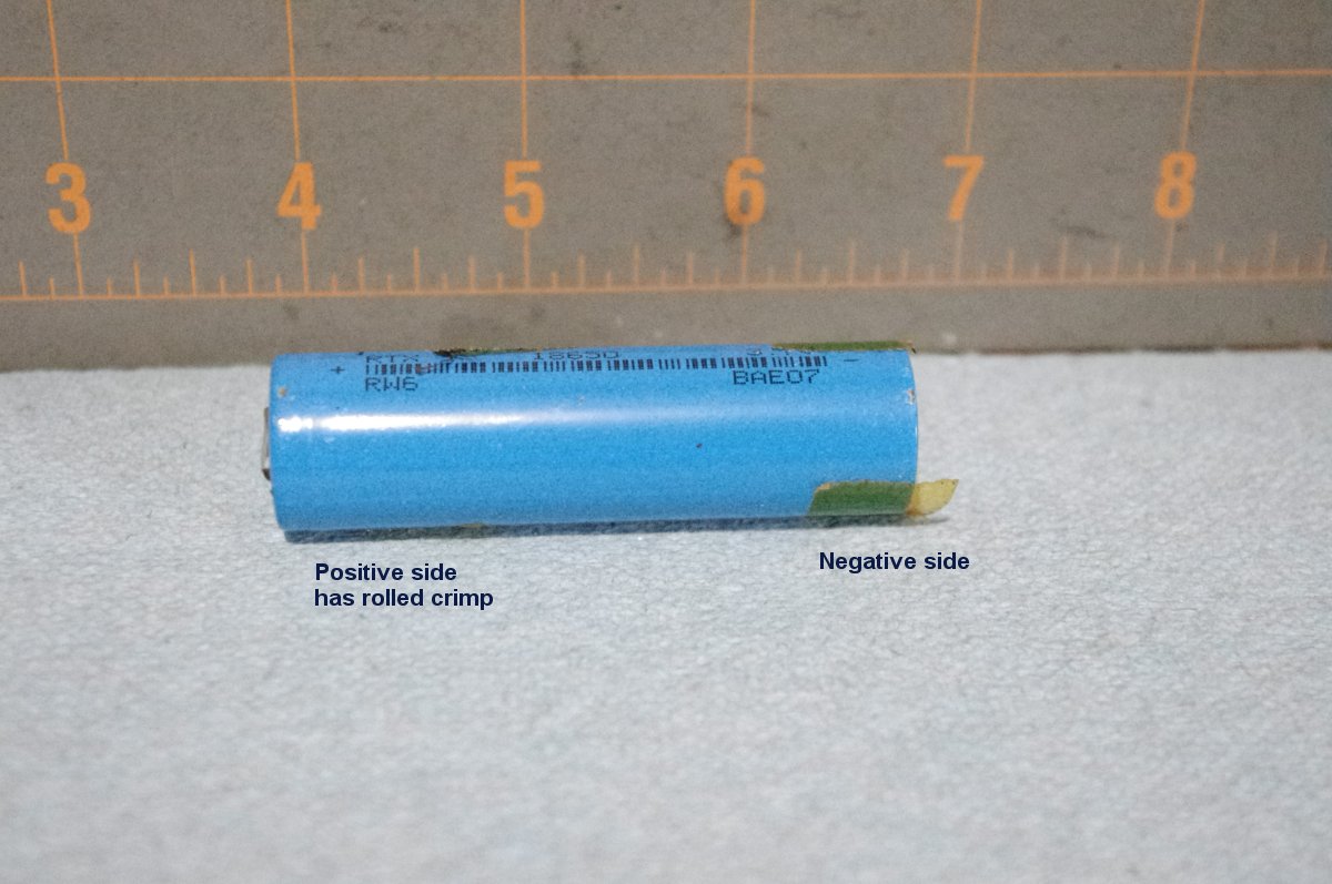
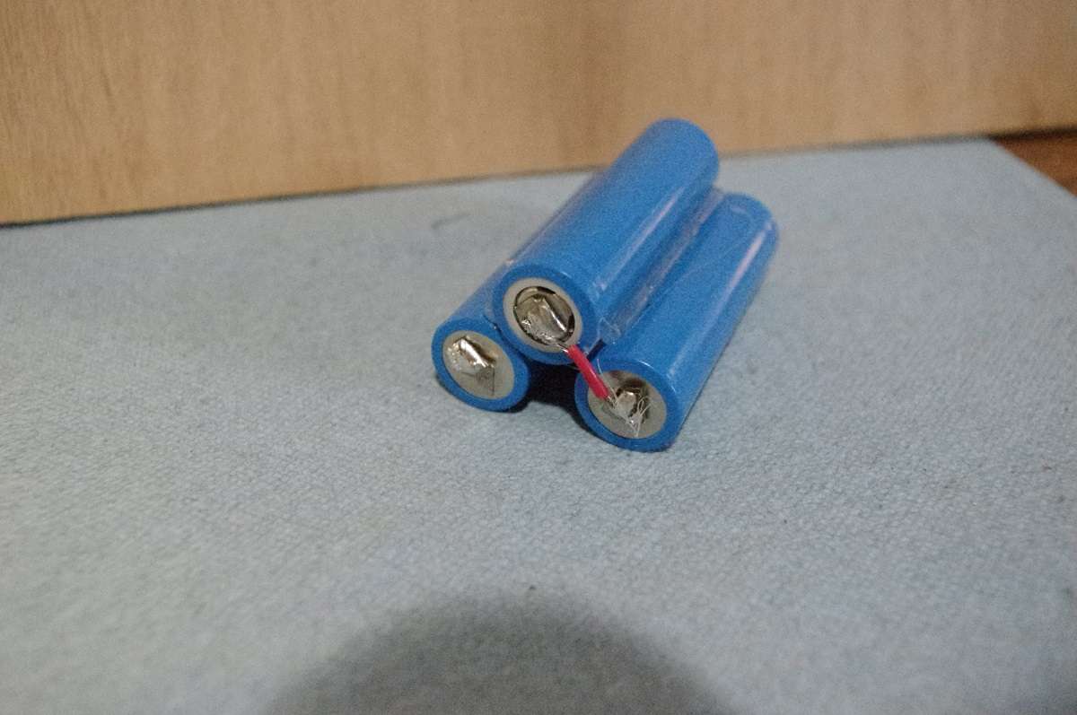
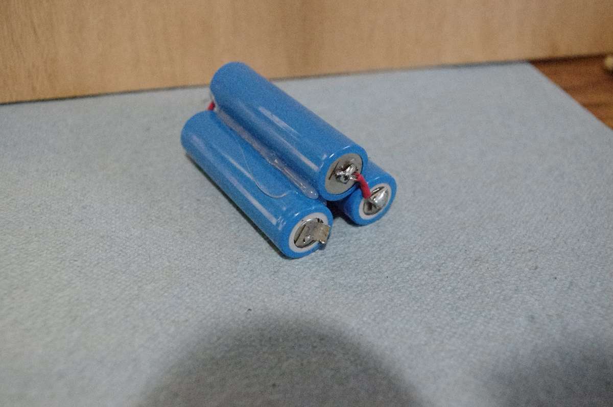
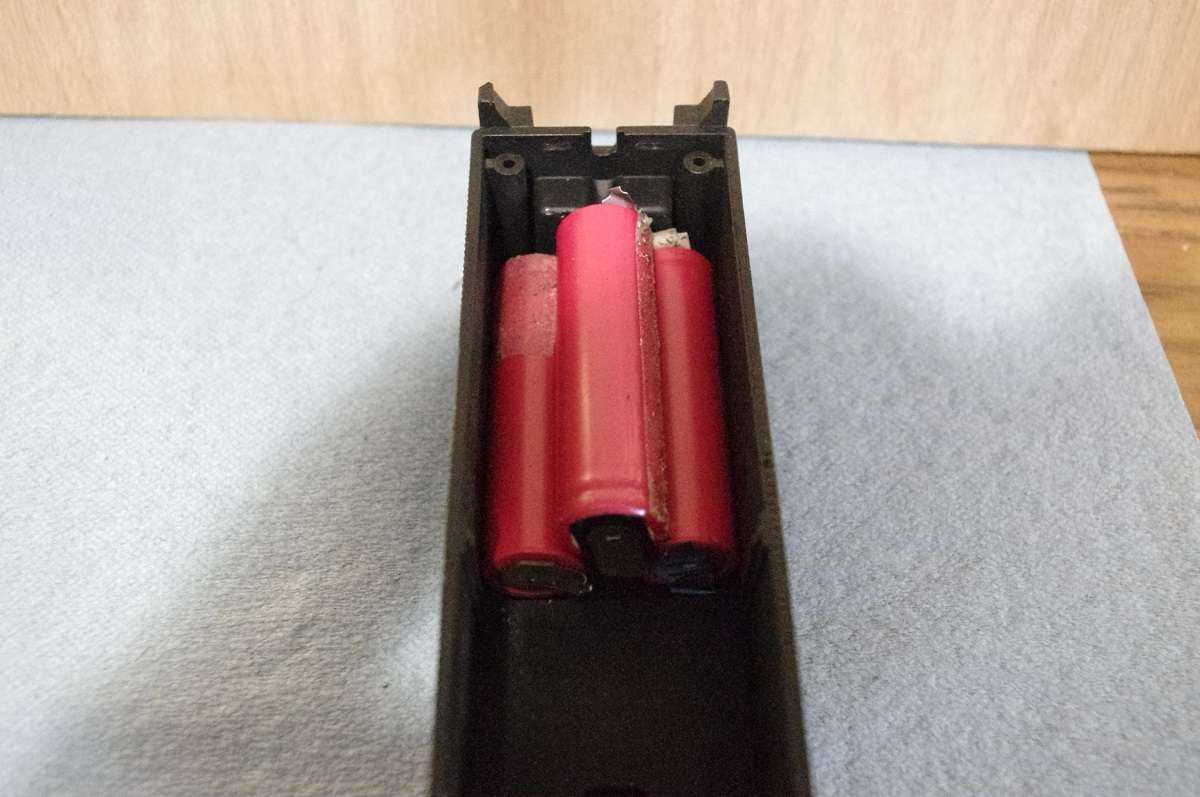
Place two lithium Ion batteries inside tender with positive (ring indented) toward front of tender shell. Prepare hot glue gun and discharge a bead inside of both batteries so the third battery keeps them separated and in place. Slide the third battery forward in the glue (negative to front of shell and positive indention to rear). I leave about 1/4 inch gap on top front to allow wire access to loco. The shell has wire slot on some models and may need to be created on others. The open part in the rear of the tender shell for other components. In the case of diesels first battery is positioned between the bosses used to secure the shell to the chassis, then hot glue is applied where batteries contact each other. Insert all three batteries in similar fashion by gluing them together flipping polarity as you go. Do not glue any of the batteries to the shell yet due to wiring the assembly before secure installation later.
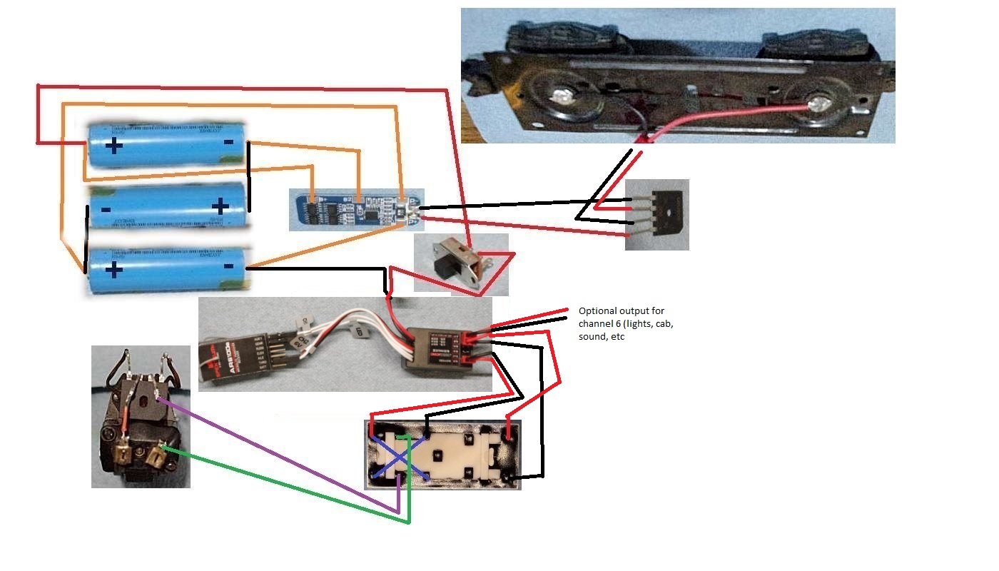
When glue is set remove the set of batteries and solder two short wires, one on each side so the batteries are wired in series as a 12.6 volt set. On front of set solder one wire from upper battery negative to power battery positive. On the other end of the battery pack solder the positive end of the upper battery to the remaining battery's negative terminal. The battery series you have created will yield roughly 12.6 volts. If during this procedure, you see sparks when you touch wires to terminals, stop immediately! Review the wiring order. The only battery that has a wire soldered to each end is the center one at this time.
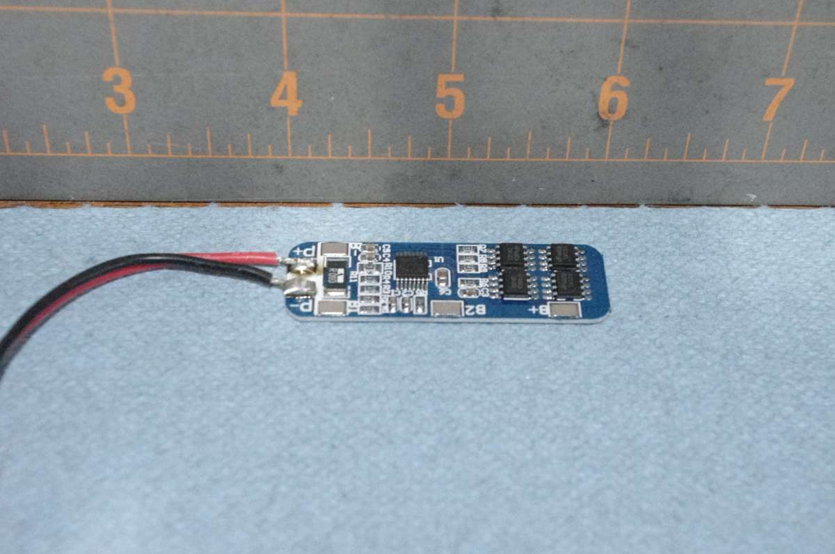
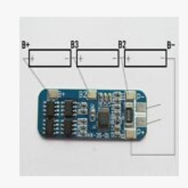
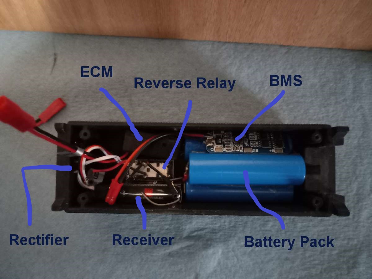
Locate the BMS charging board and solder the appropriate length of wires to the board per illustration and the model being converted. Solder the precut wires to the board. Place the battery in a fashion to allow the wires to exit the rear of the battery pack. Wires from the front typically exit down one side of the pack so there is room to fold the BMS charging board onto the other side cavity. After wires are soldered (except 2 from power in and 2 from power out) the board is protected from shorting on metal tender frame by heat shrink tape or electrical tape surrounding entire board. Tape can be used to keep the BMS balance board secure.
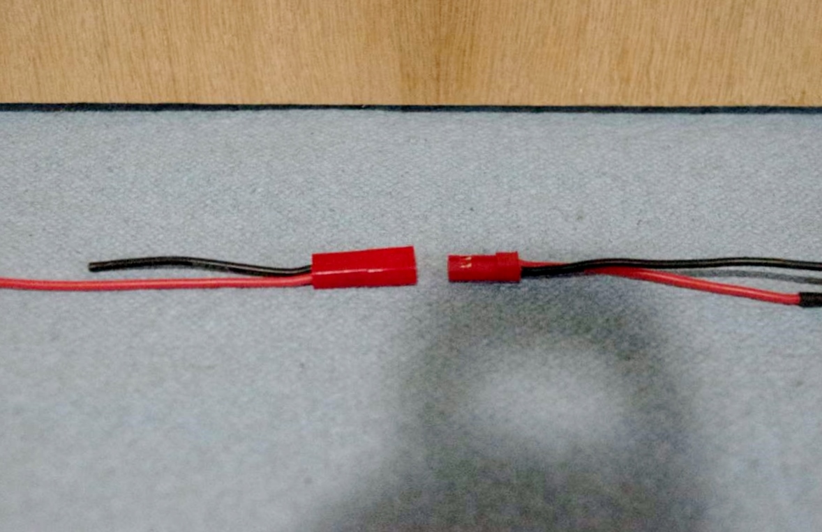
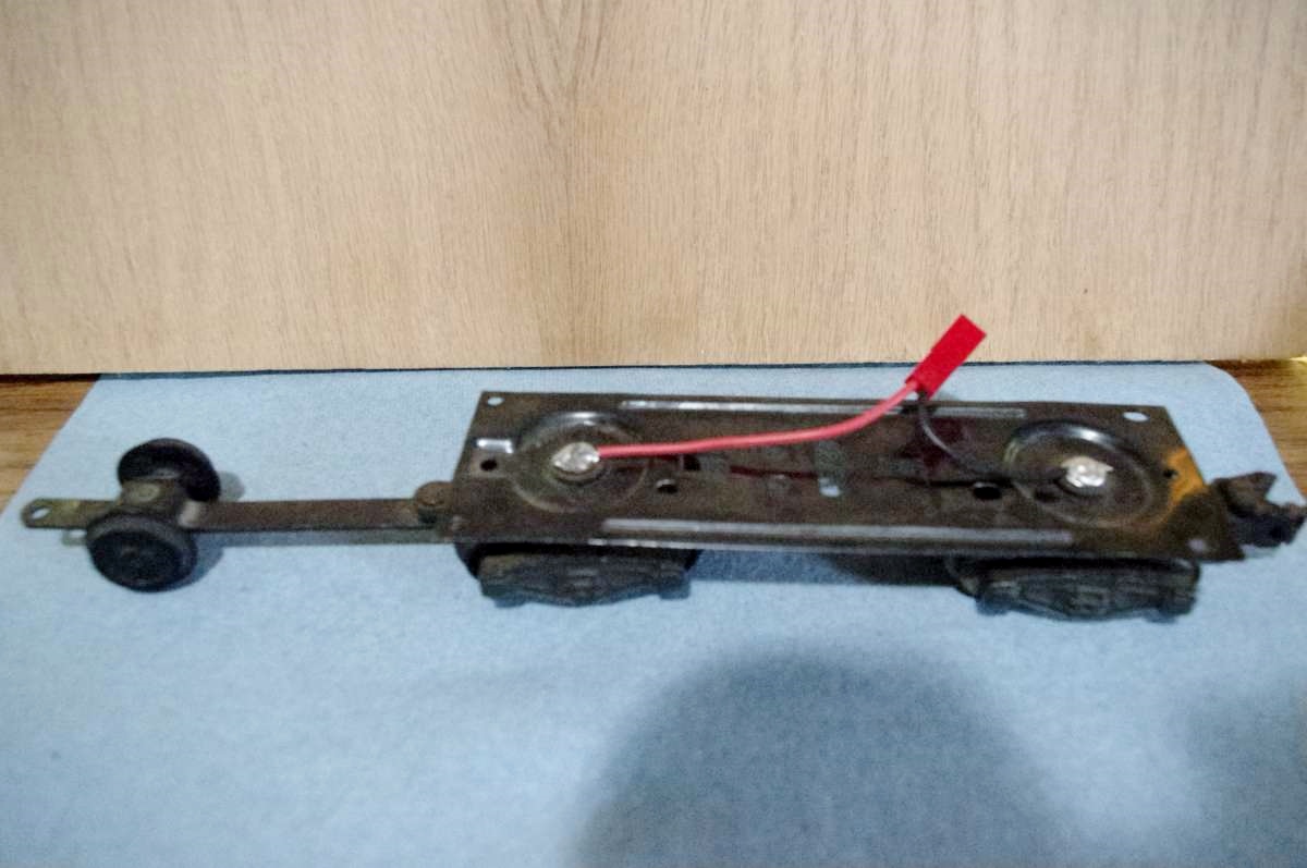
The tender rectifier is soldered to the 2 wires from the BMS charging board input (+ and -) and the tender wheel pick-ups using the two terminals identified with ( ~) AC symbols. The wire I have been using from frame to rectifier is a JST wire that has 2 pole coupler so the shell can be removed for experiments and alterations. Your call on using plug coupler or solid wires. On tender, after circuit is wired, bend leads from rectifier toward battery pack. Place double stick tape (thick type) on rear of tender and mount rectifier to it. Regarding steam units, batteries can be glued in at this time. Diesel shell has clearance issues, so chassis needs to be measured from the shell mounting hole and the clearance. The incoming charging system is complete.
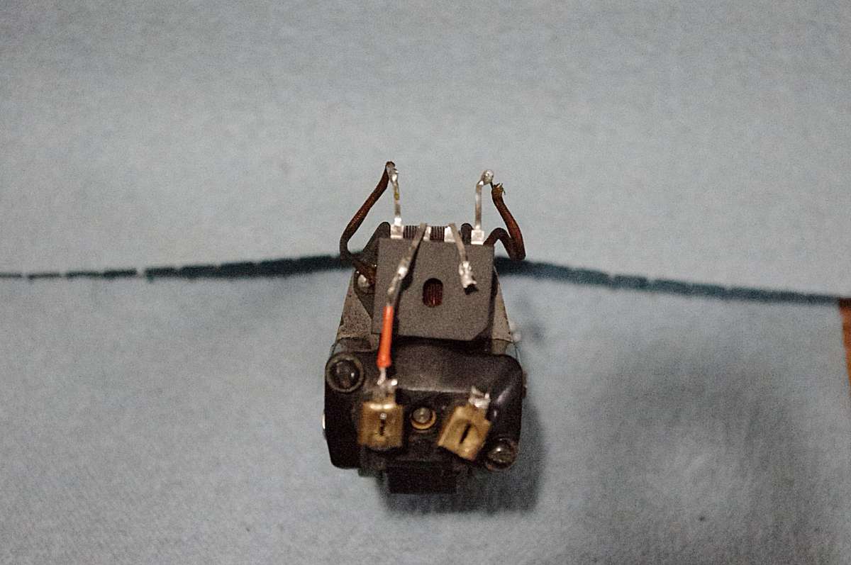
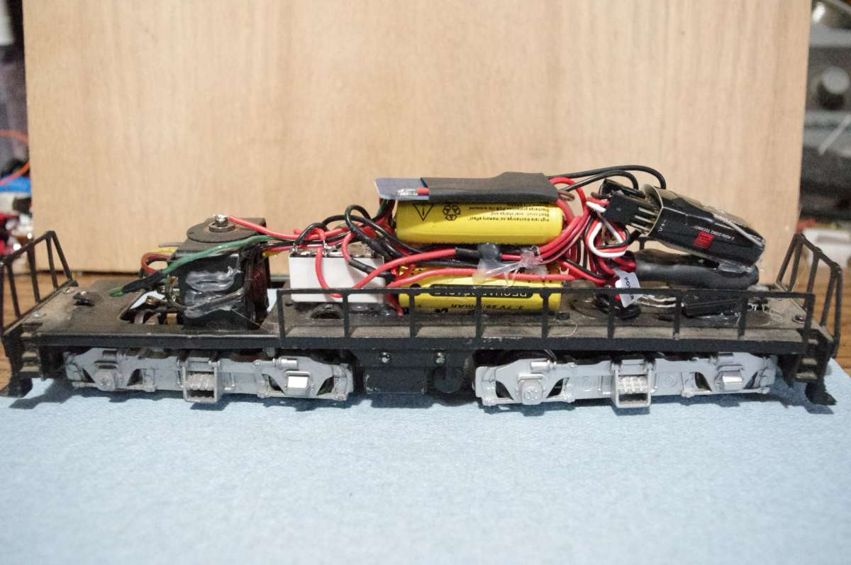
Electronic Speed Control (ESC), and receiver to get signals from transmitter are next. For the most part the distance is close between the transmitter and the control receiver so interference is minimized, although I have had a couple issues like dropout and erratic behavior. Problem was rectified by separating the ESC and the Receiver as shown. Use care when moving the antenna on the receiver. they are not designed for high flexibility. The length of antenna is important due to the frequency being used. I have replaced a couple due to mishandling and they work well. Everything fits with battery pack in front, rectifier in rear, ESC and Receiver on each side with Reverse Relay in center on the steam units. The metal shells are slightly larger in width than the plastic but plastic is more forgiving with electronics. Make sure you protect the wiring from shorts if upgrading the metal shells. Lithium Ion batteries do not like shorts. Too much rapid discharge may cause overheating.
Always insulate the wires. Heat shrink tubing works the best for me. Also consider: 1) The frame of the tender is metal and typically is one pole due to zero insulation at the joint on some models and 2) The rivets that have solder on them turn which can dig into components and 3) The smoke units on later models use the chassis ground on one pole and that will need to need to be disabled or a short will occur.