Taken from:
The Signal Engineer, October, 1914
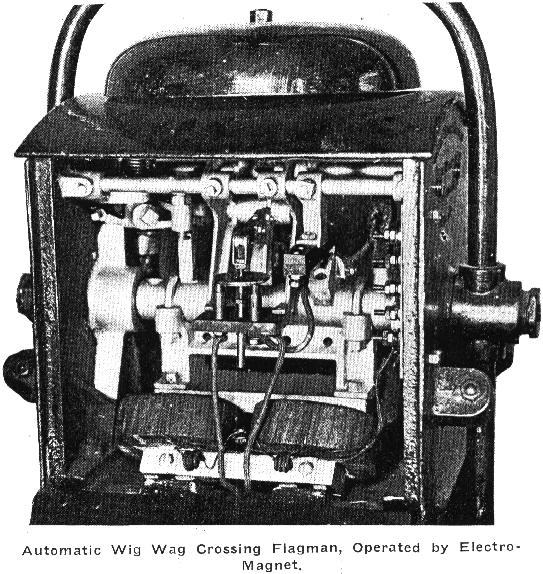
| Simplicity of operation was the goal, which was aimed
at in the development of the Automatic Flagman and Crossing Bell, illustrated
below. This device, which. is being placed on the market by the Railway
Specialties Company of Los Angeles, Cal., operates without motor or solenoid,
the operating mechanism consisting of two Electro-magnets and a switch
for turning IC current alternately from one Electro-magnet to the other.
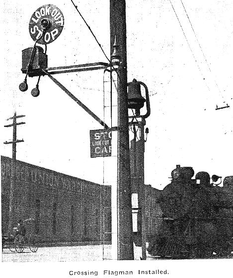
The red disk swings through an angle of approximately 72 degrees at the
rate of 60 strokes a minute, 30 strokes each way. At the same time, the
red light is turned on.
The two operating magnets may be designed for either direct or alternating current. For use on steam railways the prevailing type is wound for 8 volts, d. c. For electric railways, the windings range from 500 to 1,200 volts, d. c., and for a. c. current the windings are for 110 or 220 volt, a. c. There are but two bearings in the entire apparatus. The bearings supporting and operating the swinging target are 1 3/8 in. long and are made of babbitt. The walking-beam is separately pivoted and has ball bearings. The armature is swung below the main bearing between the two Electro-magnets. When the current is cut in, the armature is pulled toward the energized magnet and this operation mechanically throws the walking-beam switch to the opposing magnet. As the armature gets near the energized magnet, an independent circuit is cut which lights the bullseye a simple mechanical attachment to the rocker-shaft actuates the gong. For starting or stopping the signal, either the open or closed system may be employed, the closed circuit being commonly used on steam railroads in connection with an interlocking relay in the same manner as for operating the block signals. For electric railway operation, the open circuit is employed, a contactor being placed on the trolley or third rail at the desired distance. This diverts current to a high-voltage relay, which is furnished as a part of the crossing-signal apparatus. A similar contactor at the crossing disconnects the circuit as the train passes.
|
For a downloadable and printable
(Office Word) version of this, click
here.
For Acrobat (.pdf) version, clik here.
Thanks to Per Olofsson for sending this in.