Visit the TrainWeb.org Fan Page on Facebook!
Old Main Line Photo Tour

B&O Old Main Line
Modern day photo tour

Accompanying each photo below are:

Click a photo to see a larger view. Please send your comments and corrections to Steve.


Plane 1

Plane 1
Mile: 38.5 Date: Oct 2004
Ease: A View: W
Area: A IC2: 353
Map: Ca 32 F 4, Ho 2 F 5 Topographic Maps

This driveway leading up from Twin Arch Road to a junkyard marks the location of B&O Plane 1, the first inclined plane encountered on the trip west.

Basically, each of Mt. Airy's four inclined planes occupied a relatively steep area of terrain. In 1830, when the B&O planned this right of way, no one accurately knew the gripping ability of a steam locomotive's metal wheels upon metal rails. At that time, there were but a handful of primitive steam locomotives to be found anywhere, and B&O didn't have an operating one to test.

As a result, B&O chief engineer Jonathan Knight's estimate of how steep a grade future locomotives could climb was little more than an educated guess, and that guess turned out to be quite conservative. Consequently Plane 1 hardly looks formidable by today's standards.

Is this surely the location of Plane 1? The even grading, the angle, the unusual road surface, the cut, the proximity of commercial property (the junkyard) in an otherwise residential area all say a railroad had been here. The curve, however, is a puzzle. It is likely the planes were straight, or nearly straight, runs, so the I surmise the curve was added later, perhaps to facilitate room for a nearby house.

The aerial photo linked below is centered on the driveway, which at the time of the photo, shows little curvature. The base of Plane 1 was located east of the driveway's intersection with Twin Arch Road (the large road running NNW to SSE) near the sharp loop in the river.

Link: 1988 aerial photo


Plane 1 Top

Plane 1 Top
Mile: 38.7 Date: Oct 2004
Ease: B View: W
Area: B IC2:
Map: Ca 32 F 4, Ho 2 F 5 Topographic Maps

Quoting statistics from Harwood's Impossible Challenge book, Plane 1 was 2150 feet long, mostly through a shallow cut, and rose 80.4 feet. The grade was 3.7%. In 2004, this was the view west from the top.

Horses and mules assisted pulling the trains up each plane, and were then walked back down the hill to stables.

The alignment progresses on level terrain along the edge of the junkyard, past a quarry, heading for what had been a busy grade crossing with Frederick Turnpike. The base of plane 2 is 3774 feet ahead.


Road

Road
Mile: 39.0 Date: Oct 2004
Ease: C View: W
Area: B+ IC2:
Map: Ca 32 E 4, Ho 2 E 5 Topographic Maps

Part of the alignment has been erased by the quarry, but resumes at its edge as seen here. It appears to now be a road to the quarry which is also a haven for ATV riders.


Fill

Fill
Mile: 39.3 Date: Oct 2004
Ease: B View: W
Area: A IC2: 353
Map: Ca 32 D 4, Ho 2 D 5 Topographic Maps

The railroad was determined to keep the sections between the planes as level as possible. At this location, a surprising amount of fill was employed to raise the ground.


Twin Arch Bridge

Twin Arch Bridge
Mile: 39.4 Date: Oct 2004
Ease: B+ View: SE
Area: A IC2:
Map: Ca 32 D 4, Ho 2 D 5 Topographic Maps

Twin Arch Road is named for the 1900-constructed Twin Arch bridge it passes under, but few people know there had been a previous Twin Arch bridge.

Near the end of what is now Ridgeville Boulevard East are the crumbling remains of the first Twin Arch bridge. Only one arch survives, having lost its twice-as-large, adjacent sibling many years ago to road expansion. The arches carried the B&O over this small stream plus Frederick Turnpike (the National Road), Maryland's primary road to the midwest in 1830.

Note the style of stonecutting and dressing of the arch stones. I've seen it on only one other B&O bridge, that near Mill Bottom Road on the west side of the ridge. My guess is both bridges were constructed by the same workers around the same time.


Bridge Interior

Bridge Interior
Mile: 39.4 Date: Oct 2004
Ease: B View: N
Area: A IC2:
Map: Ca 32 D 4, Ho 2 D 5 Topographic Maps

The little bridge saw use for only about 8 years before the B&O abandoned it in favor of the Mt. Airy Loop alignment. However, its cousin on the west side of the ridge is still in service.


Crossroads

Crossroads
Mile: 39.5 Date: Oct 2004
Ease: B+ View: E
Area: A IC2:
Map: Ca 32 D 4, Ho 2 D 5 Topographic Maps

The little bridge of the prior picture is hidden in the brush at the left edge of this photo, which was snapped at a location I dub the "Crossroads of Mt. Airy". The now-missing twin arch had been where the pink and green lines intersect.

For over 200 years, this spot on the east side of the ridge has been a key for mid-atlantic access to the west. Initially, the Frederick Turnpike (pink) forged through, followed by the B&O (green) in 1831.

The B&O abandoned the green alignment by 1839, but in 1901 returned with the Mt. Airy Cutoff, which are the still-active tracks seen here. The railroad's grade crossing with the Frederick Turnpike was eliminated in 1930 with the construction of an overpass in distance (red), seen under construction in the photo linked below. The red route was renamed US 40 until the mid 1970s when Interstate 70 (blue) obviated it. Now US 40 and I-70 share the blue route.

Link: 1930 looks SE toward surviving arch in distance


To Plane 2

To Plane 2
Mile: 39.5 Date: Oct 2004
Ease: B+ View: W
Area: A IC2:
Map: Ca 32 D 4, Ho 2 D 5 Topographic Maps

This is the view opposite that of the prior picture. The B&O's original alignment (green, bottom left) heads toward I-70 which is behind the trees on the left. According to my calculations, the base of Plane 2 is now buried under I-70 or may even be on the other (south) side of the interstate.

The thin green line in the distance represents Plane 2 itself ascending toward the top of the ridge. The green line is at the approximate area where the plane had crossed what later became the Mt. Airy Cutoff tracks.

I have been unable to find any surviving trace of Plane 2. All of it has been completely obliterated by subsequent construction. Given that, you might wonder how I have estimated its location and path. See below.


1909 Map

1909 Map
Mile: Date: (1909)
Ease: View:
Area: IC2:
Map: Topographic Maps

My Plane 2 location estimates are based on the following two simple assumptions: 1) the planes were straight, and 2) the data Harwood published regarding the length and height of the planes is accurate. With that information, finding just a few plane endpoints lets us extrapolate the others.

I have found confirming evidence of Plane 3; it will be pictured on the next page of this tour. According to Harwood, Plane 2 met Plane 3 at the top of the ridge, separated from each other by 600 feet. Plane 2 was 3000 feet in length and rose 99.6 feet from a base elevation of 728 feet.

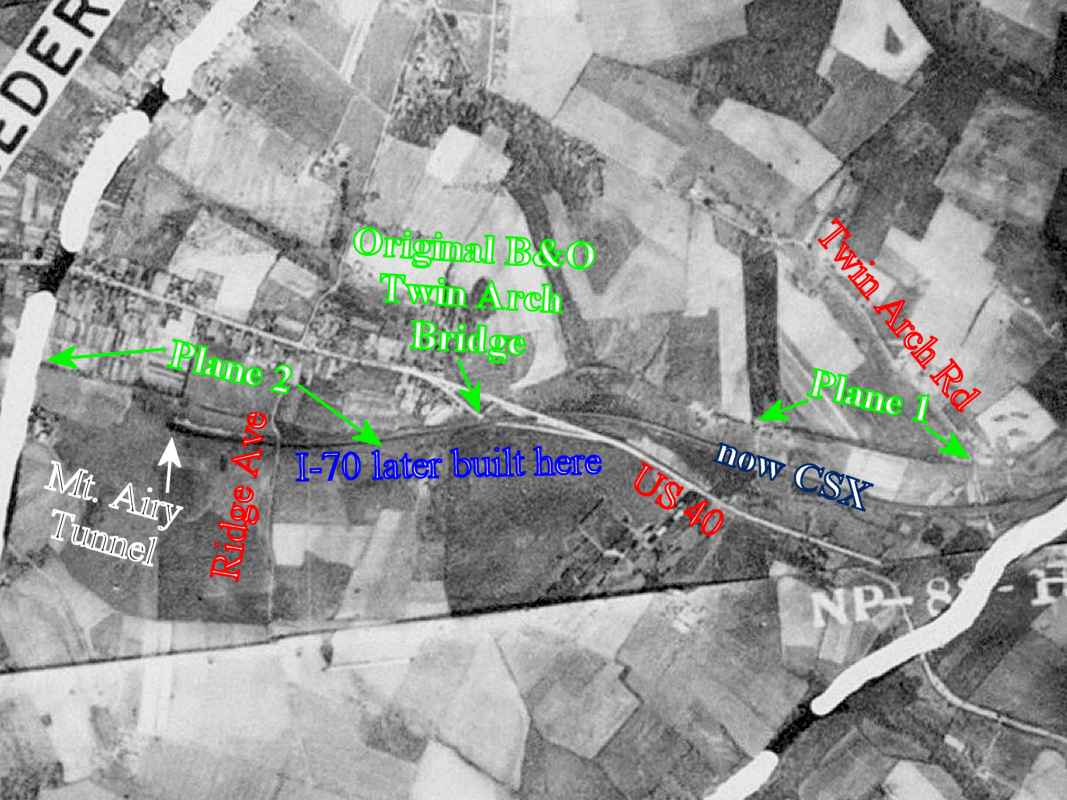
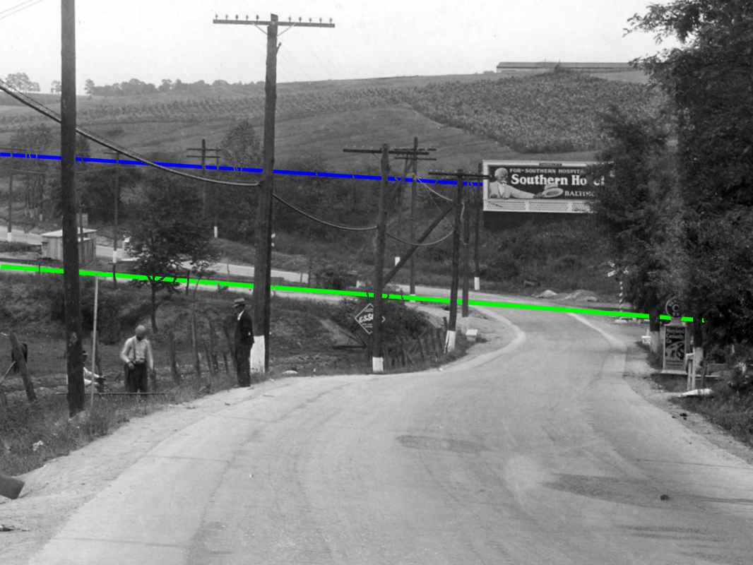
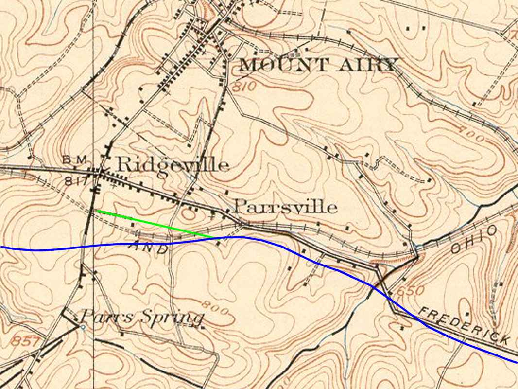
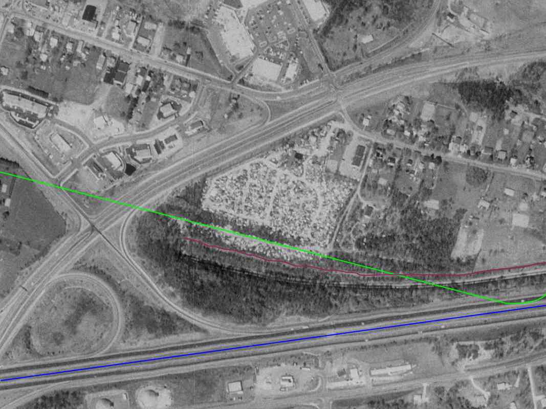
The next step is to examine topographic maps that predate I-70 and see if a line can be sketched to match that data. Pictured here is a small clip from a 1909 USGS topo map. The tracks extending across the middle are the B&O's then-new 
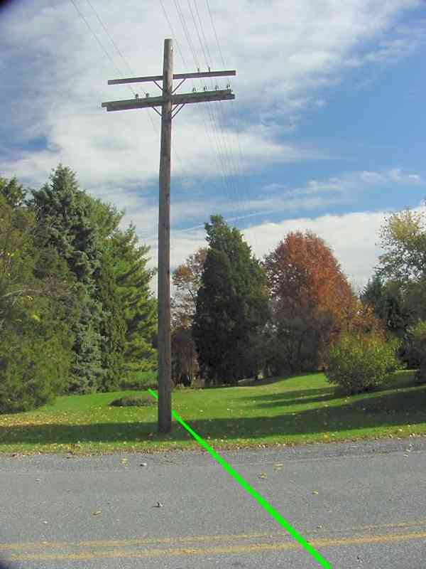
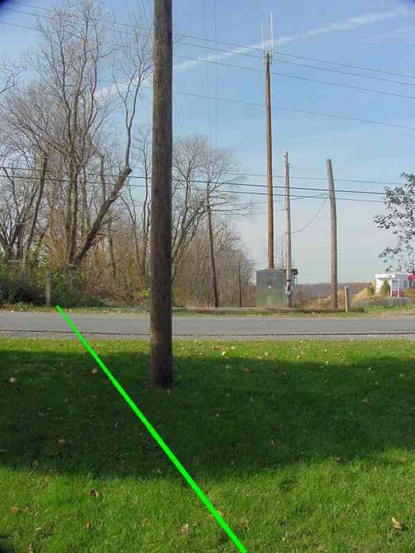
Mt. Airy Cutoff. The blue line I've added represents I-70 today. The green line designates Plane 2, and extends about 3000 feet from an elevation of about 725 feet up to one about 825 feet.

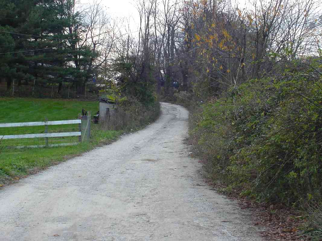
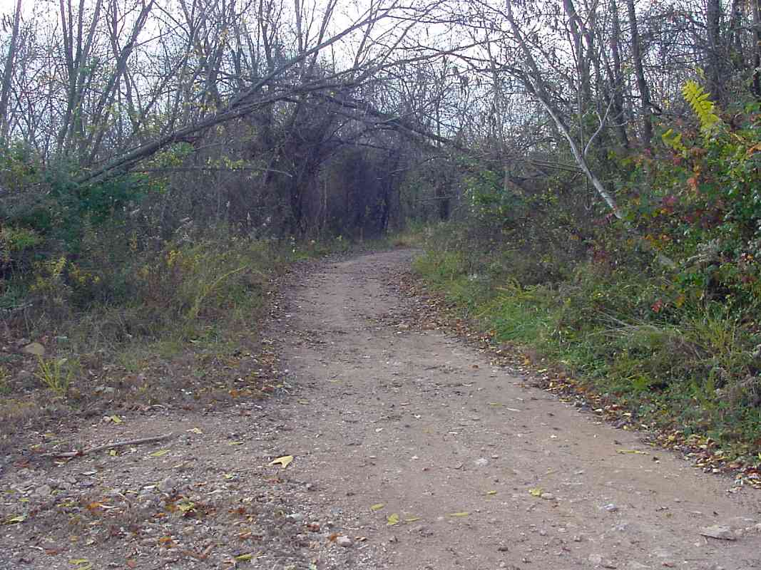
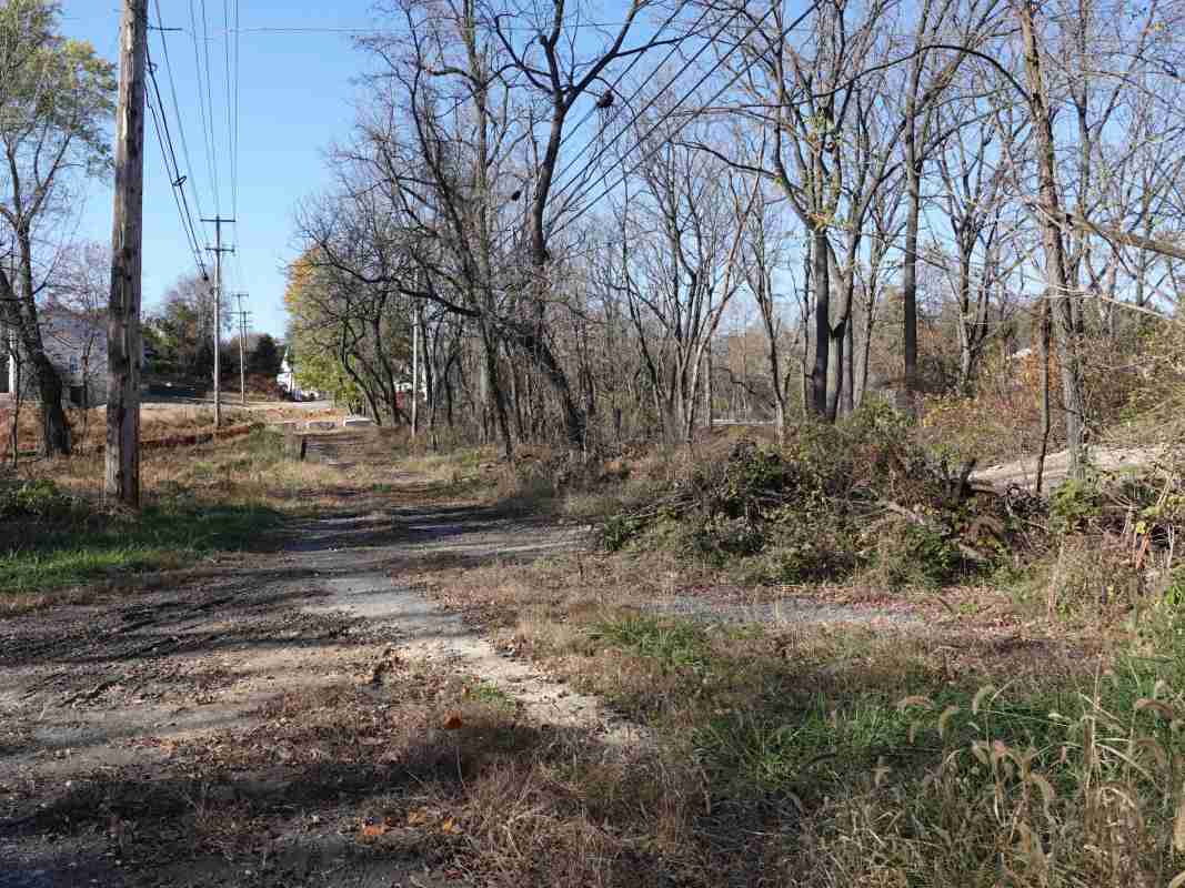
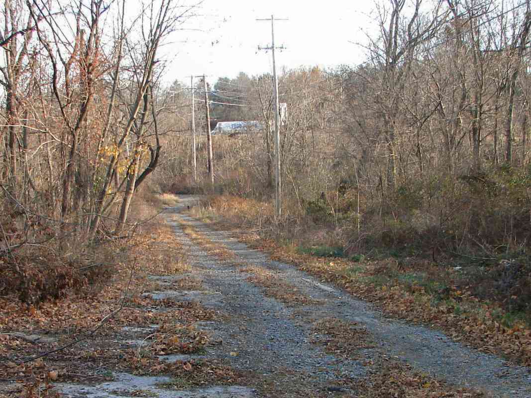
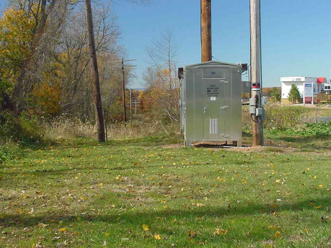
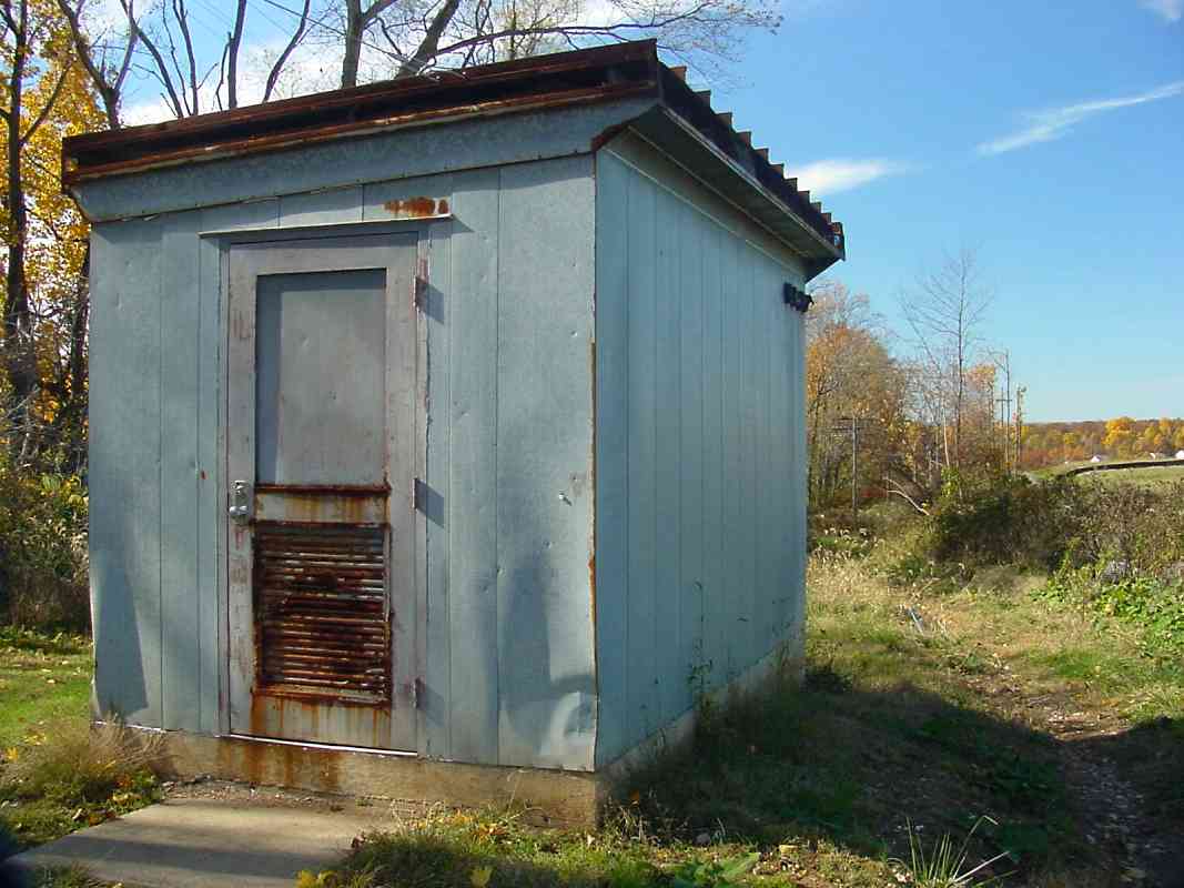
Notice how the left (west) end of the green line parallels a minor road or path, likely the remains of Plane 2. At its right end, another minor road or
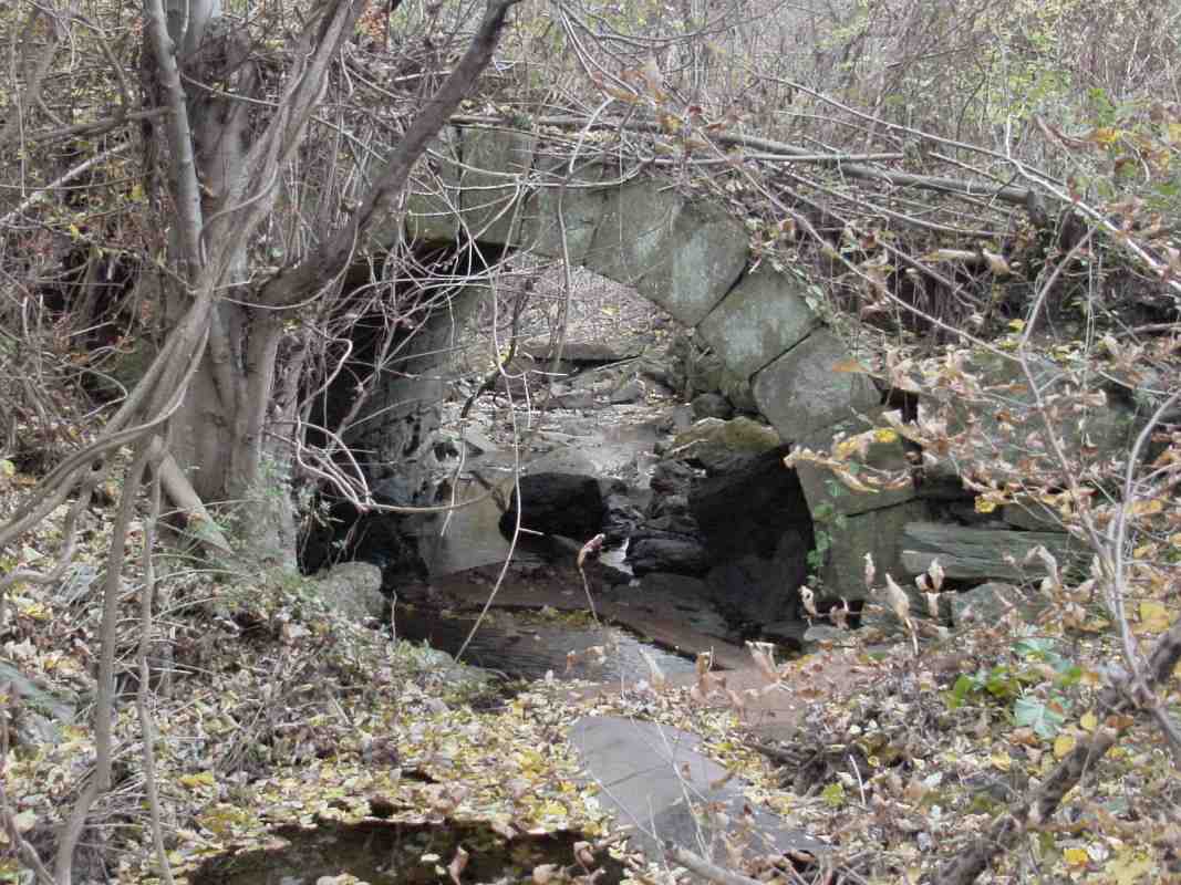
 path follows the B&O's original alignment to the base of Plane 2. At that location, the small black box represents a structure that might very well have been stables for the horses that worked the plane.


From I-70

From I-70
Mile: 39.6 Date: Jan 2005
Ease: A View: W
Area: A IC2:
Map: Ca 32 C 4, Ho 2 D 5 Topographic Maps

The green line indicates how Plane 2 might have been positioned relative to I-70 today. Bulldozers have mounded the soil so that I-70 sits at a higher elevation than the B&O's original alignment. Said another way, that alignment is now buried deep below the asphalt somewhere in this vicinity.

The blue car is roughly where I project the base of Plane 2 had been, though the base might have been all the way on the other (left) side of the interstate. In the distance are road signs for the Mount Airy highway exit. Unseen behind trees on the right are the Mt. Airy Cutoff tracks.


Pole Line

Pole Line
Mile: 39.8 Date: Jan 2005
Ease: A View: SE
Area: B+ IC2:
Map: Ca 32 B 4, Ho 2 B 5 Topographic Maps

Regrettably the Peacock Shopping Center arrived here a few years before I did. According to my measurements, its back edge has erased any Plane 2 remnants. This is the view from the loading dock area behind the stores.

As if to intentionally throw us off, the utility pole line seen here follows a hillside shelf up toward the ridge; it sure smells like railroad, but I'm convinced it's not Plane 2.

Why not? There are two reasons. First, on the other side of the ridge, there is a similar utility pole line that definitely does not mark Plane 3. Second, aerial photos that predate the shopping center show the Mt. Airy Cutoff tracks, the pole line, AND an old "scar" in the landscape that forms a straight line and is in the proper location. I believe that scar is Plane 2.

Judge for yourself. In the aerial photo linked below, you can spot I-70 running east west along the bottom. Roughly parallel and north of I-70 are the Mt. Airy Cutoff tracks (dark gray). The next parallel line (medium gray) is the utility pole line (note the slight curve, Plane 2 would not have had such a curve). And above that is another parallel line (bright gray) that would appear to be a road within what was at the time Delauder's Junkyard. That's Plane 2.

Link: 1988 aerial photo


Tunnel

Tunnel
Mile: 39.8 Date: Dec 2004
Ease: A View: W
Area: B+ IC2:
Map: Ca 32 B 4, Ho 2 B 5 Topographic Maps

Basically the same location as prior photo, now looking the opposite direction.

The dark area in the lower-left corner is the maw of the Mt. Airy Tunnel's east portal.


Dock

Dock
Mile: 39.9 Date: Jan 2005
Ease: B+ View: SE
Area: B+ IC2:
Map: Ca 32 B 4, Ho 2 B 5 Topographic Maps

The green line marks my estimate of where Plane 2 had been relative to the loading dock behind the shopping center.

The pole line of the prior two photos is behind the guardrail seen in the distance on the right.


Final Stretch

Final Stretch
Mile: 39.9 Date: Jan 2005
Ease: B View: W
Area: A IC2:
Map: Ca 32 B 4, Ho 2 B 5 Topographic Maps

The top of Parrs Ridge is seen in the distance; this was the final stretch of Plane 2.

The B&O planned to use steam winches to assist lifting the trains up each plane, but historical records are unclear if steam ever replaced the horses. There are reports of the winch system components being ordered, then later sold off, and an account that sounds like it describes a steam lifting mechanism, but little else. A definite answer may have been lost to history.

The white striped lane in the foreground is the exit ramp from westbound I-70 to northbound MD 27.

Link: ~1910 Ridgeville toll gate


Downhill

Downhill
Mile: 40.1 Date: Nov 2004
Ease: B View: SE
Area: A IC2:
Map: Ca 32 B 4, Ho 2 B 5 Topographic Maps

Plane 2 topped out right about here. The green line's distant endpoint is the location from which the prior photo was snapped.

The utility pole line re-emerges from underground. The pole line very closely follows the route of the Mt. Airy Tunnel.


Cut East

Cut East
Mile: 40.2 Date: Oct 2004
Ease: A View: E
Area: A IC2:
Map: Fr 42 B 1, Ca 32 A 4, Ho 2 A 5 Topographic Maps

I'm standing on the top of the ridge aside the aptly named Ridge Road that marks the border between Carroll and Frederick Counties.

According to data published by Harwood, the alignment pierced the ridge here within a 600-foot long man-made cut. The cut began roughly at the distant endpoint of the green line. Ridge Road was carried over via a wooden bridge. Both the cut and the bridge are long gone, but this was their location.


Cut West

Cut West
Mile: 40.2 Date: Nov 2004
Ease: A View: W
Area: A IC2:
Map: Ca 32 A 4, Fr 42 B 1, Ho 2 A 5 Topographic Maps

Back on the Carroll County side of Ridge Road, here's the view west toward the shooting location of the prior photo.

Just beyond the brush in the distance, a dirt road clearly defines Plane 3, the subject of the next tour page.

CSX has taken advantage of the high spot by installing a communications antenna, the dual spired pole on the other side of Ridge Road. It probably makes a great lightning rod.


Not Plane 3

Not Plane 3
Mile: 40.2 Date: Oct 2004
Ease: A View: W
Area: A IC2:
Map: Fr 42 B 1, Ca 32 A 4, Ho 2 A 5 Topographic Maps

Trick or treat! This photo, snapped on Halloween, at first tricked me into thinking I had found Plane 3. Only after further research did I determine the utility pole line basically follows the Mt. Airy Tunnel which is deep underground here. Plane 3 is actually adjacent on the left; new houses are going up on the right.


Booth

Booth
Mile: 40.2 Date: Oct 2004
Ease: A View: W
Area: A IC2:
Map: Fr 42 B 1, Ca 32 A 4, Ho 2 A 5 Topographic Maps

Next to (behind) the shiney new communications box is this older structure. My speculation is it tops a ventilation shaft for Mt. Airy Tunnel.


Forge ahead to the next page in this tour

Or, return to main page


Copyright Notice

Visit the TrainWeb.org Fan Page on Facebook!
Create your own free Rail Blog or Website!

Advertise | About Us | Contact Us | Sign up for our Newsletter | TrainWeb.com