


| British Railways (Western Region) Tokenless Block |
|||||||
|
This page describes a system of Tokenless Block working for single lines, which was introduced originally by British Railways (Western Region) (BR(WR)) in 1967 for use on the former London & South Western Railway (L&SWR) main line from Salisbury to Exeter. Although BR(WR) seem to have considered that their system would get widespread use, apart from a few other isolated sections the Salisbury - Exeter line remained its only extensive use for some considerable time. However in due course it was introduced at several locations on other former BR Regions and eventually there were quite a few sections worked by this method, although subsequently many have been superseded by other systems. There have been a number of variants of the system in use, but the general principles remained essentially the same.
Please Note: this page describes the Tokenless Block system as originally provided for the Salisbury - Exeter line. Most of that installation was superseded by Track Circuit Block in 2012, when control of the signalling between Tisbury and Pinhoe was transferred to the Area Signalling Centre at Basingstoke (click here for further details). Therefore the information on this page is now more a matter of historical record than a description of current-day practice, but it may prove a useful reference in respect of the few surviving examples of this system.
In 1967 the line from Wilton (just west of Salisbury) to Pinhoe (just east of Exeter) was reduced to single track with a few passing-loops, although a short section of double-track was retained from Templecombe to Yeovil Junction. Existing signal-boxes and their mechanical lever-frames were retained to work the revised layouts at the passing-loops, but with colour-light signals replacing almost all of the semaphores. (Click here for further details about the Salisbury to Exeter line since the 1967 changes.) It was envisaged that, with reductions in staffing levels for economy, the signalmen would be employed on other duties between trains - so, with the long single-line sections and increased running times, it was essential to have a block system that did not require a signalman to be present to 'accept' a train before it could enter a section. Furthermore the avoidance of a system which required the physical exchange of tokens would enable running speeds to be maintained at signal-boxes where station stops were not required.
The BR(WR) system depended upon the use of special block instruments, track-circuits and treadles. Track-circuiting did not extend through the block section itself and only a treadle and two short track-circuits at the entrance to/exit from the block section were required for the operation of the basic system, although in practice the passing-loops tended to be fully track-circuited (and needed to be so at signal-boxes that could 'switch-out'). The avoidance of the need to track-circuit the entire block section reduced the installation costs, but it did mean (in principle) that a signalman had to be present at the exit from a section to check for a tail-lamp to ensure that the complete train has left the section. This was not considered to be a problem in the case of the Salisbury - Exeter line at the time of the original installation, but subsequent alterations resulted in a number of locations (both on that line and elsewhere) where a train could leave a single-line section remote from the controlling signal-box. In such cases reliance was placed upon the fact that all trains normally using the section were fully-fitted with continuous automatic brakes and therefore there was a low risk that a broken coupling would leave behind one or more vehicles obstructing the section un-noticed.
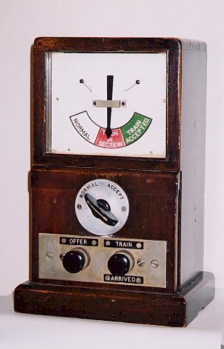 |
The BR(WR) Tokenless Block instrument consists of a single-needle indicator with 3 positions (labelled 'Normal', 'Train In Section' and 'Train Accepted'), a 2-position rotary 'acceptance' switch ('Normal' and 'Accept') and two push-button switches ('Offer' and 'Train Arrived'). The block instrument betrays its BR(WR) origins, as the wooden case is similar to that used for the 'single-deck' version of their standard commutator block instrument (often used for 'permissive' instruments), and it may well be that the instruments were converted from redundant items. Block-bells are not provided with this system, as the method of operation does not require them, although in practice the signalmen tended to use the bells of the box-to-box telephones. |
It should be noted that the 'Normal' indication is given by the needle pointing to the left, rather than being vertical in the centre as is usual with most 3-position indicators. The reason is that in this tokenless block system, unlike most 3-position block systems, there is a continual flow of electric current through the line wires to hold the indicator over to the 'Normal' position. In the event of an electrical failure, then gravity causes the needle to fall to the central 'Train In Section' position and provides a 'fail-safe' indication (this situation can be seen in the photograph, where the instrument has been disconnected). Some of the instruments were manufactured with the central legend on the indicator reading 'Line Blocked', but this has been covered by a sticky label bearing the 'Train In Section' legend.
To describe the basic operation of the system, let us assume that the signalman at box 'A' wishes to send a train to his colleague at 'B'. If the instruments are normal (and all else is in order in accordance with the Regulations) then A pushes his 'offer' button - provided that B turns his acceptance switch to 'Accept' (or has done so already), then the indicators on both instruments will go to 'Train Accepted' and the lock on the section signal at A will be released. When the train passes the section signal it will occupy a track-circuit, which causes the section signal to change to a red aspect and both block indicators to go to 'Train In Section'. When the train arrives at B and passes beyond the home signal it will operate a treadle, and occupy and then clear two track-circuits in succession - upon completion of this process a 'train arrived' condition will be registered within the system. When the signalman at B has seen the train arrive clear of the single-line complete with tail-lamp he returns his acceptance switch to 'Normal' and presses his 'Train Arrived' button - if the 'train arrived' condition has been proved then both indicators will return to 'Normal' and the block is clear.
It must be emphasised that, when A presses his 'Offer' button, there is no visual or audible indication at B that a train is being offered. The design assumption with this system was that trains would run according to the timetable, and so B would have placed his switch to 'Accept' already in anticipation. (It is possible for both signalmen to keep their switches at 'Accept', so that the first one to 'offer' gains the section.) This 'pre-acceptance' feature means that B does not have to be present in his signal-box in order for A to offer or despatch the train. If B should find it necessary subsequently to stop the train leaving A then, provided that the block is still in the 'Train Accepted' condition, he has merely to return his switch to 'Normal' - the indicators will return to 'Normal' and the release on the section signal at A will be cancelled. The section signal is normally a colour-light, so cancellation of the release causes the signal to change automatically to a red aspect, even if signalman A is not present in the signal-box to replace the signal lever. (It is permitted to have a semaphore section signal, in which case the cancellation causes a warning buzzer to sound continuously until the signal lever is returned to normal.) Conversely A can cancel his 'offer' by turning his own switch to 'Accept' temporarily, whereupon both block indicators will revert to 'Normal'.
There are a number of variations between the circuits used for this system and those for the various forms of ordinary 'three-position' block, such as the standard BR(SR) and BR(WR) commutator instruments. This system requires four line wires (plus earth return), whereas most 3-position systems manage with a maximum of three wires (plus earth return) and that includes one line for a bell circuit. The block indicators at each end are not in series, but activated by separate local circuits. Perhaps the most important difference is that, in the 'Normal' condition, electric current is flowing all the time through the block indicators as well as two line wires - absence of current gives the 'Train In Section' indication. This arrangement ensures that, with a complete electrical failure, the instruments will fail to a 'blocked' status. For further details click here to see a wiring diagram showing a simplified version of the original design of the circuits between two signal-boxes.
A further advantage of this block system is the relative ease with which 'switching-out' facilities can be provided at intermediate passing-loops. Reversible signalling is provided on one loop and a 'switch lever' is included in the locking-frame - it is necessary also to provide full track-circuiting through both loop roads in order to detect the presence or absence of trains. The reversal of the switch lever controls a relay that 'cascades' together the block circuits for the block sections on either side of the switching-out signal-box. A 3-position 'switching indicator' is provided that shows 'IN/-/OUT' as appropriate, depending on the position of the switch lever and its relay.
A signal-box can be switched 'out' if one of the following conditions applies:
For cases (1) or (2) above the signalman must place the "Acceptance" switches on both his block instruments to 'Normal' and get his colleagues on either side to place their own switches to 'Accept'. Then he presses both 'Offer' buttons, which causes both block indicators to go to 'Train Accepted' and releases the lock on his switch lever. When the switch lever is reversed both indicators will go to 'Normal' in case (1) or 'Train In Section' in case (2). In case (3) only the instruments for the unoccupied section are operated - with one block indicator already showing 'Train In Section', once the indicator of the other block instrument goes to 'Train Accepted' the switch lever becomes free, and when that has been reversed then both indicators will show 'Train In Section'. The switching indicator should show 'OUT'.
A signal-box can be switched 'in' only if one of the following conditions apply:
In the former case the signalman must arrange for his colleagues at the adjacent boxes to place their Acceptance switches to 'Accept' and then he must press both his 'Offer' buttons - when both block indicators show 'Train Accepted' the switch lever can be replaced to normal, whereupon both indicators will revert to 'Normal'. In the latter case, as both indicators will be showing 'Train In Section' already, after replacing the signals to 'on' the switch lever is free to be returned to normal - the signalman then must press both 'Train Arrived' buttons, which will restore both block indicators to 'Normal'. The switching indicator should show 'IN'.
The system includes facilities for the control of ground-frames (GF) at intermediate sidings in block sections. On the Salisbury - Exeter line these GFs were standard BR(WR) pattern, mechanically unlocked by an Annetts Key kept in an adjacent Key Release Instrument (KRI). In addition, where 'shut-in' facilities are provided, there is a two-position block indicator ('Normal' and 'Line Blocked'), a 'Train Shut In' plunger and a 'Release' plunger. When a train arrives to shunt the siding it stands on a track circuit adjacent to the points - after one minute the key can be removed from the KRI and the GF unlocked. If the train is not to be shut-in then the key is retained until shunting is complete, after which the GF is re-locked, the key returned to the KRI, and the train continues on its way.
If the train is to be shut-in then, once it has been shunted clear of the single-line, the GF is re-locked and the key restored to the KRI. The person-in-charge (PIC) at the GF then holds down the 'Train Shut In' plunger until the indicator moves to 'Normal' - at this stage the block indicators in the signal-boxes at either end of the section will have moved to 'Normal' also. When the train is ready to leave the siding the PIC must telephone the controlling signalman, and in turn he will telephone the other signalman. Provided that the section is clear and all is in order both signalmen will turn their acceptance switches to 'Accept', then the PIC will operate the 'Release' plunger, which will enable him to withdraw the key from the KRI. Once the train has been drawn out onto the running line, and the GF re-locked, the key is returned to its KRI. The occupation of the track circuit by the train leaving the siding will move the block indicator at the GF to 'Line Blocked', and the block indicators at both signal-boxes will go to 'Train In Section'.
A number of minor variations have crept into the system. On the Salisbury - Exeter line there was a section of double-track between the signal-boxes at Templecombe and Yeovil Junction. The Up line was signalled for reversible running and therefore it was worked by tokenless block in the same way as other single-line sections. However the Down line was worked in the one direction only, so a modified form of the system was used on that line. The instrument at Templecombe had no 'Acceptance' switch and (presumably) the corresponding instrument at Yeovil Junction had no 'Offer' button. In addition no treadle was provided at the exit from the Down line section at Yeovil Junction, so clearance of the block was governed solely by the 'Train Arrived' button. The instrument at Templecombe did retain a 'Train Arrived' button, which probably was provided to enable the block to be cleared when a shunt into the forward section had been withdrawn.
In 1981 the signal-box at Wilton was closed and control of the section to Gillingham was transferred to a new power signal-box at Salisbury. The basic Tokenless Block system was retained, but the 'block instrument' at Salisbury took the form of switches and coloured lights built into the operating panel of the new signal-box. A similar arrangement was installed in the panel of the replacement signal-box at Chard (Junction) in 1982, and also in 1988 when the signal-box at Pinhoe was closed and its work taken over by a replacement panel in Exmouth Junction signal-box.
In 1986 a new intermediate passing-loop was opened just east of Tisbury, which was controlled by Salisbury panel. This loop split the original section to Gillingham into two new sections (Wilton - Tisbury - Gillingham), so additional switches and lights were incorporated in the panel at Salisbury to provide ' block instruments' for Tisbury. As a result, in order to send a train from Salisbury to Tisbury the signalman at Salisbury has to 'offer' a train to himself! Click here to see a picture (120KB) of the relevant part of Salisbury panel. Since the 2012 signalling alterations the section from Wilton to Tisbury is the only section of the line between Salisbury and Exeter still worked by tokenless block.
© Chris Osment 2002 & 2014
|
|
© West Country Railway Archives 2002 Page last updated: 05 Aug 2014 |
Home Page: http://www.railwest.org.uk E-Mail: railwest@bigfoot.com |
||||||


