Token Configurations |
|
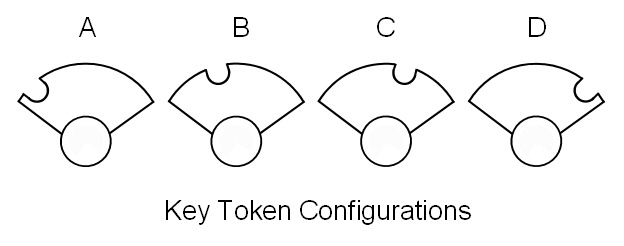
On any single line with more than one token section, it is essential that the tokens of adjoining sections differ in some form or the other. They can be of different shapes, colours and where electric tokens are used, have different configurations of notches etc to only allow them to be used in the correct machine for the section. TYER KEY TOKENS Tyer keys come in a variety of shapes and colours but the feature that distinguishes the key from its neighbours is the slot on the key end. The following is a view from the handle end of a token, showing the relative positions of the slots.
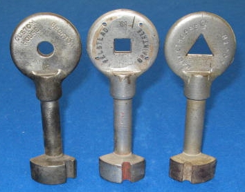
As stated, the slot is what determines the configuration but as an extra aid to identification keys can have additional features. In some cases the key handles are of different shapes and have a central hole, the handle and the hole shapes being 'A' Round, 'B' Square, 'C' Triangular, 'D' Diamond (square turned through 45 degrees).
Some key token handles are all the same shape regardless of configuration but have the central hole.
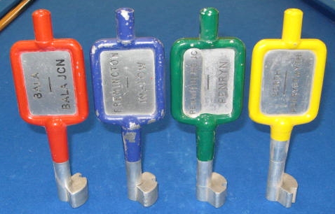
Others, the handles are the same shape but they are painted to indicate which configuration they are, 'A' Red, 'B' Blue, 'C' Green, 'D' Yellow.
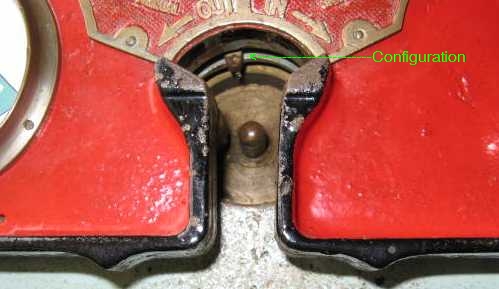
The picture below shows how the configuration is set on the instrument, this protrusion only allows key tokens of the same configuration to enter the instrument, in this case it is set at the 'B' configuration. The protrusion is part of a metal plate that can be fixed in any one of the four standard configurations.
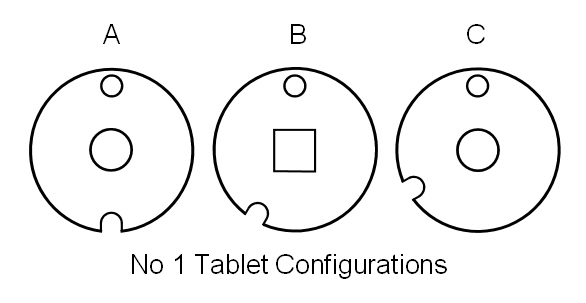
TYER No 1 TABLETS On Tyer No 1 tablets the configuration is determined by the relative position of the slot on the circumference and the small hole. Note - Although I have annotated the sketch below with the configurations A-C, I have found no evidence that this is in fact correct. (If you know the correct annotation, please let me know!)
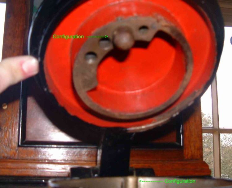
Some tablets have a central hole, some just have a depression in the centre, to aid identification. Being the first design of electric token, the shape of this central hole/depression doesn't necessarily follow the accepted standard that latter tokens adopted. The photo below shows the raised lid of a No 1 Tablet machine, at the bottom of the picture you can just make out the nib which engages with the slot cut in the side of the tablet. On the lid is the pin that engages with the hole in the tablet. In this case the pin is in the 'B' configuration, and shows three other possible positions and room for another.
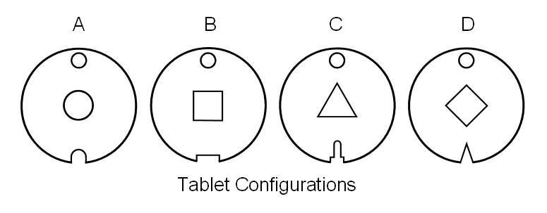
TYER No 6 TABLETS (also No 2, 3, 5 & 7) On these tablets the configuration is purely the shape of the notch at the bottom. The hole at the top, unlike the No 1 tablets, does not play a part in the configuration. Most tablets also have a central cut out which normally follows as below.
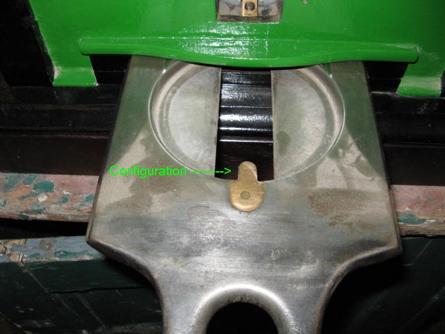
The slide where the tablets are inserted into the machine, has a corresponding nib to match the configuration of the tablet, The picture below shows an 'A' configuration, as fitted to a Tyer No 6 instrument.
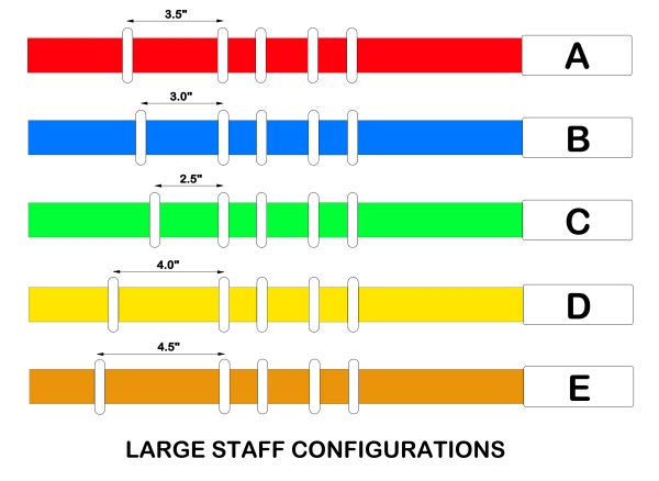
LARGE STAFFS The configuration is determined by the position of the 5th ring, as an additional aid the staffs are sometimes painted, however most of this paint doesn't survive in service.
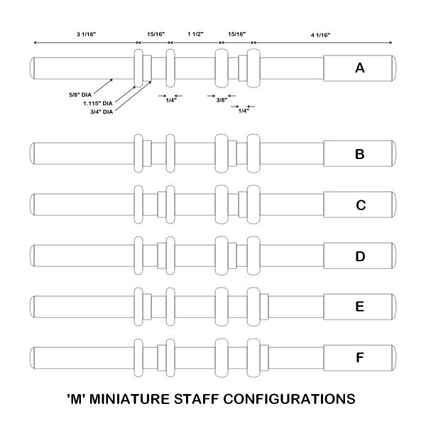
MINIATURE STAFF 'M' TYPE These staffs dispensed with the 5th ring and the configuration is determined by the position of the small collars, to ensure that the staff is inserted the correct way into the instrument one pair of rings are a larger width than the other pair.
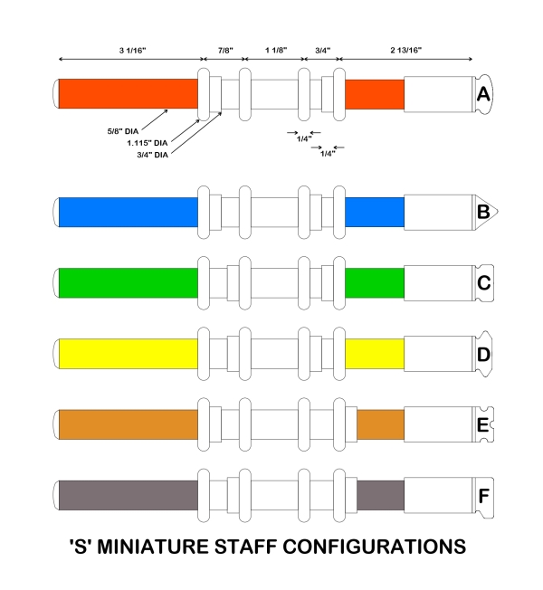
MINIATURE STAFF 'S' TYPE The configuration arrangements are identical to the 'M' type above. To ensure the staffs are inserted into the instrument the correct way, the rings (which are all the same width) are spaced differently.
|