![]() Under the Hood of a TGV
Under the Hood of a TGV
|
Serve this page from: California, USA / Pisa, Italy |
Between the pantograph and the traction motors of a TGV there is a whole set of power electronics with the task of "processing" a fixed voltage at the (single-phase AC or DC) catenary to produce a variable force at the wheel treads. These power electronics fill most of the space inside a TGV power car.
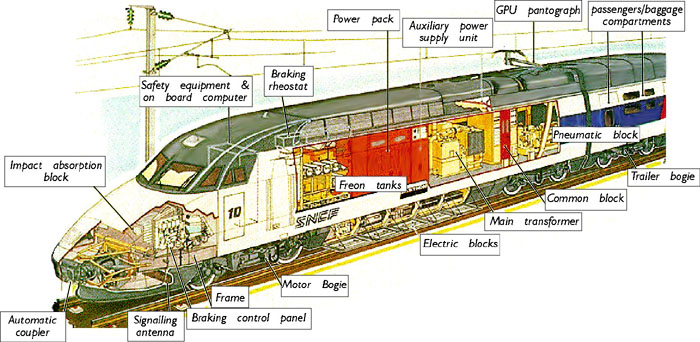
We follow the power chain from pantograph to wheels, in the specific case of the TGV Atlantique 24000 series power car. The TGV 24000 does not contain any particularly exotic components, and in principle shares many of its features with most modern electric (and even diesel-electric) locomotives. The drawing below shows a cutaway view of the 24000, and is followed by a more detailed description. There are two power cars per trainset; each develops 4400 kW (5900 hp) and weighs just 68 tonnes (150,000 lb).
Drawing: B. Bayle (SNCF Direction du Matériel) in Revue Générale des Chemins de Fer, December 1986Traction Components
GPU Pantograph: GPU means "Grand Plongeur Unique" (large, single plunger). [A pantograph is a device used to draw electrical power from a fixed overhead wire]. The GPU pantograph was specially designed, with a top linkage member (holding the wiper) that operates like a hydraulic damper with a short stroke to keep intimate contact with the overhead conductor and keep bouncing to a minimum. Contact wire pressure is about 70 N (17 lbs). The bottom linkage, wich guides alignment with the contact wire, is locked at a fixed height when operating under the fixed-height overhead on high speed trackage.
Main transformer: takes 25kV 50Hz single phase overhead power and converts this to 1500V 50Hz. For information on how transformers work, pick up any college physics textbook. The transformer is one of the heaviest components in the unit, weighing about 8 tonnes. It is located in the lower frame of the unit, and sits in a bath of oil, circulated by pumps and cooled with fans.
Thyristor controlled-rectifier bridge: as the name implies, rectifies the ouput of the main transformer to make 1500V DC. The thyristors allow a refinement beyond a simple diode bridge: they not only rectify the current, but can act as a switch and "chop" (turn on and off) the output power. This is why we speak of a "controlled rectifier". There are two thyristor-diode bridges, one for each pair of traction motors. From now on in the traction chain, in fact, there are two separate and independent paths to each of the two power trucks (bogies). This is to maximize reliability. (under 1500V DC overhead power, all that is used up to here is a thyristor chopper.)
(A note about the thyristor: these are made use of extensively in the TGV, just as in most modern electric locomotives. The development of the thyristor has made possible the use of frequency controlled AC traction motors and revolutionized traction circuit design. The thyristor is basically a switch, albeit a very large one, which resembles a common transistor in the way it works. A thyristor passes current only in one direction, called the "forward" direction, providing that a suitable voltage is applied to its control electrode, or "gate". As long as this gate voltage is not present, current cannot flow through the device.)
Common block: consists of the DC circuit breaker (two of them working in tandem, actually) and the main filter capacitor, which smooths the chopped 1500V waveform to a lower DC voltage, depending on the duty cycle.
Traction inverters convert their DC input into a computer-controlled three phase, variable frequency AC waveform, in order to conrol the traction motors. There is one inverter per traction motor. The inverters are thyristor-based. For each truck (bogie), the two inverter/motor pairs are connected in series. The power electronics physically associated with one truck (bogie) correspond to a "motor block" or "power pack". There are thus two such power packs installed in each power car. If one of them experiences a fault, it automatically isolates itself. The driver can then switch it back on, without leaving his station, by resetting the circuit breaker. But only once-- if the fault persists, the power pack will again trip out and, this time, stay down. This is not a problem in practice, since there is enough spare traction power available that the train can continue on its journey, on three packs out of four total. (Recall that TGVs have two power cars; one on each end of the train.)
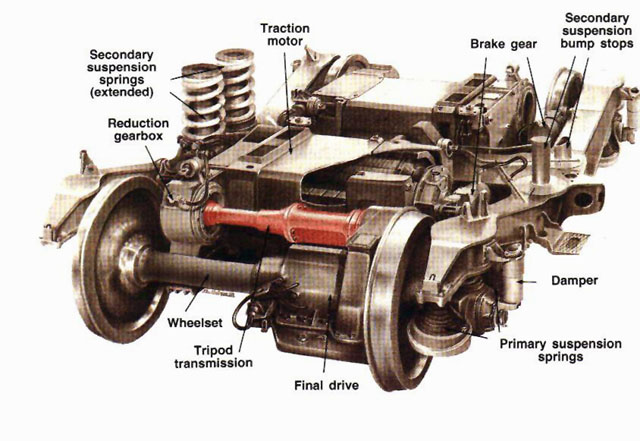
Synchronous AC traction motor: the motor is excited at a frequency proportional to its rotational speed. There is no collector as on DC motors, which allows a reduction of wear and maintenance costs. (Note: the synchronous AC traction motor is different from asynchronous AC (induction) traction motor. Whereas the latter has a simple cage rotor with no power connections, the synchronous motor has rotor coils fed through slip rings.) In an unusual arrangement considered to be one of the TGV design's strong points, the traction motors are slung from the vehicle body, instead of being an integral part of the Y230 power truck (bogie). This substantially lightens the mass of the truck (each motor weighs 1460 kg), giving it a critical speed far higher than 300 km/h (186 mph) and exceptional tracking stability. The traction motors are still located where one would expect them: in between the truck (bogie) frames, level with the axles, but just suspended differently. Each motor can develop 1100 kW (when power comes from 25kV overhead) and can spin at a maximum rate of 4000 rpm.
Mechanical transmission: the output shaft of the motor is connected to the axle gearbox by a tripod transmission, using sliding cardan (universal-joint) shafts. This allows a full decoupling of the motor and wheel dynamics; a transverse displacement of 120 mm (5 inches) is admissible. The final drive is a gear train that rides on the axle itself and transfers power to the wheels. This final drive assembly is restrained from rotating with the axle by a reaction linkage.
Drawing of the Y230 power truck (bogie).
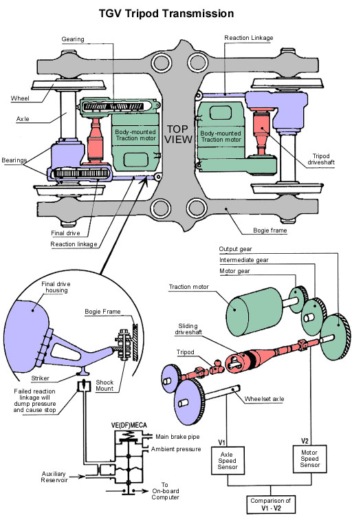
Schematic of the TGV's tripod transmission.Sensors continuously compare motor speed to axle speed. A discrepancy between the measured speeds indicates a tripod driveshaft failure condition, which is indicated in the cab. If the tripod transmission develops a dangerous vibration, the shaking reaction linkage can strike a pneumatic valve that automatically dumps the main brake pipe and stops the train.
Other Components
Besides the main traction chain, there is of course a whole suite of auxiliary equipment inside the TGV power car.
Braking rheostat: large air-cooled resistors, located in the roof of the unit, used to dissipate braking power generated by the traction motors while braking. Also known as "dynamic brake"; in this application it is used exclusively at high speeds, and combined with wheel brakes as the speed drops below a predetermined level. Overall they can take up almost half of the braking energy in stopping a trainset from full speed. There are two sets of rheostats, one for each power pack. Their effective resistance can be modulated by the chopper to vary braking effort.
Pneumatic block and wheel brakes: the main compressor is used to fill the air tanks used for the braking system. These tanks are located underneath the frame of the unit. There are two brake lines running the length of the trainset, as is common for the electropneumatic brake system used on most passenger trains. The first, the "principal line", is maintained at a pressure of 8 or 9 atmospheres at all times and is used to fill the auxiliary brake reservoirs on each vehicle in the trainset. The second, the "general line", modulates the wheel braking level between full application (3.5 atmospheres) and full release (5 atmospheres).
Auxiliary power supply unit: a static converter that generates head-end electrical power for the rest of the train. HEP ("hotel power") is 380V 50Hz, while interior lighting is supplied with 72V DC. Output of the converter also runs some equipment in the power car: the transformer oil pumps and cooling fans, the brake rheostat cooling fans, the thyristor cooling fans, etc.
Automatic coupler: the Scharfenberg-type coupler makes pneumatic and electrical connections without external intervention. It allows to couple two TGV trainsets nose to nose, either for normal multiple unit operation (even at high speeds) or for towing. When not in use, the coupler is concealed by two fiberglass clamshell doors that form the nose of the unit. These can open away to each side to reveal the coupler.
Impact absorption block: is an impact shield to defend the cab cubicle. The deformation of this thick aluminum honeycomb block absorbs a part of the collision energy if a large object is struck.
Frame: Primary structural members, made of high tensile strength steel. The main structure of the unit is a rigid space frame. In more recent designs, crashworthiness has been improved by including sacrificial frame members that collapse and absorb energy in the event of a large impact.
Sinalling antennas: mounted under the front air dam, two antennas read TVM 300 (and more recently TVM 430) cab signal information from the rails, and relay them to the train's central computer (which in turn displays them to the engineer). There is a more detailed description of the signalling system available.
On-board computer: manages all the subsystems. The computer can help to diagnose faults, and can even generate a maintenance report which is transmitted by radio to the shops prior to the train's arrival. Because the computer is so closely involved in every aspect of the operation of a TGV Atlantique unit, software glitches can cause annoying problems. Early teething problems in the computer systems actually made the TGV Atlantique initially less reliable than its older, lower-technology counterpart.
TGV Trailers
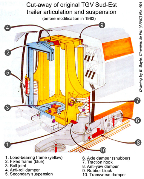
Cutaway of a TGV trailer articulation (by B. Bayle).A TGV power car isn't the only place in a trainset to find interesting mechanical features. The diagram above shows a cutaway of the articulation between two TGV trailers. This cutaway is somewhat out of date because the suspension was since redesigned. The current design differs mainly in the arrangement of shock absorbers and the replacement of the big secondary suspension spring by a pneumatic spring. For a detailed description of the new SR10 pneumatic suspension, see article.
More Information
Some pictures taken at the factory and in maintenance will show you some more details on how they are put together. You will be able to recognize several components as mentioned above.
Also don't miss the excellent summary of how railway vehicles are manufactured, by Paul Berkley and Piers Connor on the Railway Technical Web Pages. While general in nature, this document has some detail relating to TGV high speed trains.
This document was created with the help of Prof. Miguel R. Bugarin at the University of La Coruna, Spain. The tripod transmission diagram was provided by Jean-Emmanuel Leroy.
Last modified: March 2000