1967 Tube Stock Original Cab Photos
Fig. 1: 1967 Tube Stock
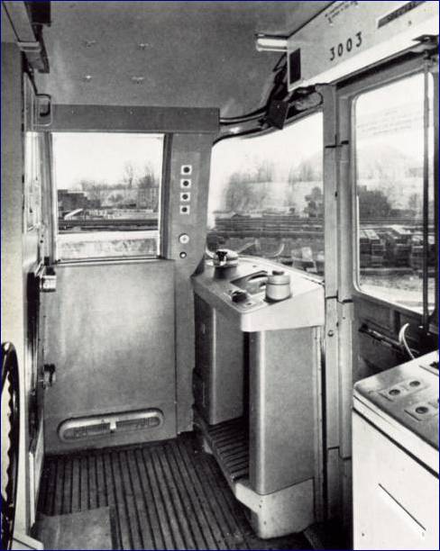
Cab as built
 This is
the interior of the 1967 Stock cab in original condition. The control desk was an
integrated design for the first time in a London Underground train. Previous driving
positions just had the essential controls scattered around within easy reach of the
driver. This is
the interior of the 1967 Stock cab in original condition. The control desk was an
integrated design for the first time in a London Underground train. Previous driving
positions just had the essential controls scattered around within easy reach of the
driver.
Below the desk there was a kneespace heater and a tip up seat
was hung off the rear cab wall. There were no side doors. It was decided very
early on in the development of the automatic train that it would be dangerous to have side
doors. The driver could start the train and then fall out of the door if it was
open.
To allow the driver to look out, a drop window was
provided. It had to be raised to be almost closed before the train could be
started. It was provided with a mechanical interlock. Again, it was thought
that it was dangerous to let trains run with the cab windows fully open. The window
had to be closed to within about a 4 inch gap.
Another feature of the stock was the interlock on the front
cab door (known as "M" door), which also had to be locked to allow the train to
start.
The wheel just visible on the rear wall is the handbrake pump
wheel. The 1967 Stock originally had hydraulic parking brakes which were applied by
this handwheel.
In the ceiling over the driving seat position four bolt holes
mark the location of the train identification system known as "Identra".
This is not fitted on this particular train but it was provided for the whole fleet.
The destination of the train is set by the driver, who turns a dial. The information
is transmitted to tunnel mounted receivers and is used to verify the train description
system in the control room and along the line.
The destination blind at the front over "M" door is
hand operated.
To the Top of this Page
Fig. 2:
Original Layout of Driving Controls
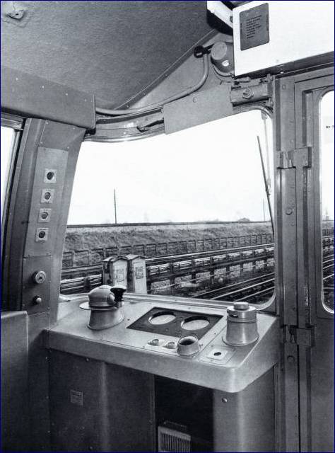 A combined traction/brake
controller (CT/BC)was provided on the left hand side and a key operated selector switch on
the right hand side. The two are mechanically interlocked to prevent the CT/B) being
moved without a key in position. A combined traction/brake
controller (CT/BC)was provided on the left hand side and a key operated selector switch on
the right hand side. The two are mechanically interlocked to prevent the CT/B) being
moved without a key in position.
The selector switch provides forward or reverse manual
driving and automatic operation. It is operated by the standard reverser key used on
all the older stocks.
Between the two main controls are air and speed gauges.
Around the speedo, illuminated indicators show which auto code is being detected by the
train. Below are various indicators showing that doors are closed and motor
alternators running.
A large button is provided on the edge of the desk.
This is the deadman device, which is only required while manual driving is in use.
The driver has to keep this depressed all the time the train is being driven in
manual. Next to it on the left are the two automatic start buttons. On the
right is the trip reset button. This is provided to reset the code trip valve when
the cab is being activated.
The left hand pillar contains, from the bottom up, whistle
button, window wiper control, and overload and MA controls. A sonalert is provided
to indicate when a speed limit is being reached under manual driving.
Door controls were originally on the rear cab walls.
Since refurbishment, they have been provided on the side window ledge.
To the Top of this Page
Fig.
3: The offside cabinet of 1967 Tube Stock as originally built.
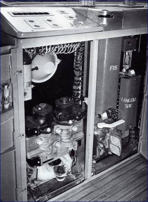 The doors of the
cabinet are open to show the Uncouple switch on the far right and the FIS (Fault Isolating
Switch) next to it. The doors of the
cabinet are open to show the Uncouple switch on the far right and the FIS (Fault Isolating
Switch) next to it.
The uncouple switch was a new concept on the 1967 Stock,
designed to overcome the problems with the remotely controlled automatic couplers used on
earlier stocks. The uncouple switch allowed each coupler to be operated
independently, eliminating the problems of earlier designs which required both couplers to
synchronise.
The FIS provided on the 1967 Stock was also a new version of
the traditional concept that a stalled train could be got going again, provided you
isolated the defective bit and used the good bit to move the train. The FIS could
divide the traction control system from the middle of the train but you had to go there to
do it. The 1967 version of the FIS allowed either the front half or the rear half of
the train to be isolated from the front cab.
On the left hand side of the cabinet is the code trip valve,
audible warning valve and audible warning reset button. An changeover cock is
provided for the conversion of the train from automatic operation to manual operation on
another line. If this is required, a tripcock must be fitted. This is done at
Northumberland Park Depot when a train has to be transferred off the Victoria Line.
The transfer point occurs at Finsbury Park where there is a
junction with the Piccadilly Line. The train is run from Northumberland Park Depot
to Finsbury Park in ATO mode. At the junction signal, the train is stopped and the
driver changes over to manual and moves the changeover cock to bring the tripcock into
operation and cut out the code trip valve. The train can now be driven onto the
Piccadilly Line when the junction signal is cleared.
On top of the console there are additional ATO start buttons,
heater and lighting control buttons, plus a row of miniature circuit breakers which double
as switches for the cab, head and tail lights. The refurbished 1967 Stock has had
the heaters removed.
To the Top of this Page
Fig. 4:
Rear offside cab wall of 1967 Tube Stock in original condition.
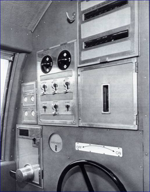 On the left is the
door controller. This was a simple rotary switch, which had to be moved up to open
the doors and down to close the doors. There was a simple switch to cut out the end
doors. On the left is the
door controller. This was a simple rotary switch, which had to be moved up to open
the doors and down to close the doors. There was a simple switch to cut out the end
doors.
Above the door controller are test sockets and
next to them are the cut out switches for various items such as door interlocks, control
governor, rheostatic brake, compressor and e.p. brake. Above are the cab heater
switches.
The wheel operates the hydraulic parking brake
and there is an ON/OFF indicator. Above it is a sight gauge to show the level of
fluid in the handbrake pump system. This system gave a lot of trouble and was
removed during refurbishment.
Above the sight gauge there are two rows of
miniature circuit breakers.
Back to Victoria Line ATO
|


