


|
Links to pages on this site:-Signalling Index |
|
| 420 pulses per minute | Full speed. |
| 270 pulses per minute | Restricted speed up to 25 mi/h, remotoring allowed. |
| 180 pulses per minute | Restricted speed up to 25 m/h, no motoring allowed, train should be braking to zero. |
| 120 pulses per minute | Not detected by the train. Used for track circuit purposes only. If a train gets this far it has overrun a stop signal. There is no filter on the train for the 120 code, the effect of this being that the 120 code is treated as though no code were present, its purpose is to operate track signalling diagrams. |
The codes are fed into the unoccupied track circuits as shown under "Track Equipment" on the right of the diagram below.
Fig 1: Diagram of signalling code generators used to feed coded track
circuits and the train equipment used to detect the codes.
The code generators are activated by signalling relays which respond to the condition of the track circuits ahead of the particular location. If the line ahead is clear for full speed, the 420 relay will close and the 420 code generator will send 420 ppm into the running rails.
Pick up coils mounted on the train a few inches above the running rail are used to detect the frequency of current flowing in the rails. In this way, the track circuits are used to convey the continuous safety codes to the train. Two safety coils are used, one over each rail, to prove that the current flowing in both rails is the same.
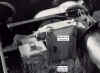
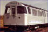 The
pick up coils are illustrated in Fig. 2 (left) which shows the leading end of a 1967 Tube
Stock train in original condition.
The
pick up coils are illustrated in Fig. 2 (left) which shows the leading end of a 1967 Tube
Stock train in original condition.
Click on the image for the full size view and description.
If a 420 code is present, its respective code filter passes steady dc supplies to the trip valve coil, to the Auto Driver Box and to an indicator light on the drivers control desk. The 270 and 180 code filters will do likewise when their respective codes are present but the feed to the trip valve in this case will be interrupted if the speed exceeds 25 mi/h. This is effected by a mechanical governor which breaks the circuit above that speed. In addition, to guard against the train moving backwards, a "run back" detector breaks the feed to the trip valve if that should happen.
To the Top of this Page
 The
code trip valve, Fig. 3 (left), is the ATO equivalent of the tripcock. The currents
induced in the code detector coils are amplified in the safety box which, if the frequency
is correct (in our example, 420 ppm), keeps the code trip valve energised. It is
connected to the brake pipe of the train and, if it is de-energised, it dumps the brake
pipe air pressure, causing the train's emergency brakes to apply. Failure of the track
circuit, the codes or the on board tuned circuits will result in the train being tripped
at once, so the system is "fail safe".
The
code trip valve, Fig. 3 (left), is the ATO equivalent of the tripcock. The currents
induced in the code detector coils are amplified in the safety box which, if the frequency
is correct (in our example, 420 ppm), keeps the code trip valve energised. It is
connected to the brake pipe of the train and, if it is de-energised, it dumps the brake
pipe air pressure, causing the train's emergency brakes to apply. Failure of the track
circuit, the codes or the on board tuned circuits will result in the train being tripped
at once, so the system is "fail safe".
Click on the image for the full size view and description.
To the Top of this Page
Until 1984, all train overhauls were done at Acton Works. So that the 1967 stock could operate over the (Piccadilly Line) non-ATO route to Acton, it had to be fitted with a tripcock. This is mounted on the shoebeam in the usual way and it is connected to the brake pipe through a hand-operated changeover cock in the cab. The "trip valve/tripcock changeover cock" as it is called, allows either the trip valve to be selected for Victoria Line ATO operation or the tripcock for non ATO operation.
The connection between the Victoria Line and the rest of the Underground system is with the Piccadilly Line at Finsbury Park. A tripcock tester is provided at the exit from the Victoria Line to make sure the train has its tripcock fitted. When the train arrives at the exit signal, the driver will changeover to tripcock operation so he can drive at normal speed on the Piccadilly Line. Photo.
1967 Stock is not allowed in passenger service on the Victoria Line with the tripcock fitted. After all, the whole safety system is based on the operation of the code trip valve if the train attempts to run outside the speed limits set by the coded track circuits. If the driver attempted to select the (unfitted) tripcock by using the changeover cock, the brake pipe air would be lost and the train would not start.
To the Top of this Page
Sometimes a train has to be moved without codes. This is done in the depot at Northumberland Park. It is known as "Slow Manual" or SM. To enable the train to be moved when no code is present, an "on code/off code" switch is provided in the cab. To keep the trip valve energised, the train speed must not exceed 10 mi/h when this switch is in the "off code" position and a vigilance button provided on the driver's control desk must be held pressed down while the train is being driven. This system enforces the depot speed limit, provides a speed limit when trains have to be worked in service with a failure of the safety equipment and serves in place of the deadman's handle. To assist the driver under these conditions a warning device sounds when the speed approaches 9 mi/h.
To the Top of this Page
In order to understand how the ATO signalling system works, it is necessary to mention the need for a safe braking distance. If a train travelling at (say) 40 mi/h is tripped, it will travel about 600 feet (200 m) before coming to rest. So, to ensure safety for the train, it must be stopped before it can enter an occupied block. The way to do this is to trip the train if it enters the block before the occupied one. Such a section is called the "overlap" and its length will be at least that required for a train to come to rest from maximum possible speed.
The length of the overlap will depend largely upon the maximum speed which the train will attain when running through that section. It will be seen therefore that the length of the overlap will depend on the braking distance. To reduce the length of the braking distance it is necessary to reduce the speed of the train. For ATO conditions, this is done by what is known as controlled speed running.
The automatic train detects the codes for the sections over which it is running by means of the safety coils on the train. If the frequency of the current in these codes is altered according to the maximum train speed permitted, the overlap distance can be reduced automatically for slower speed running.
Fig 4: Diagram showing London Underground Victoria Line
signalling safety codes which occur behind a train standing at a station.
In the diagram (Fig. 4) above, the train standing in the station is protected by the 120 and 180 codes behind it. The 180 code begins at the start of the full speed safe braking distance (the full speed overlap). This means that if a following train enters the 180 code track circuit at full speed, it will be tripped by its code trip valve, the emergency brakes will apply and the train will be brought to a stand before it reaches the train in the platform - probably somewhere in the 120 code area. Remember that the 180 code only permits a speed below 25 mi/h, that's why a train doing over 25 mi/h gets tripped.
Of course, if every time a following train enters a 180 code section at more than 25 mi/h it was to get tripped, it would make for a rough ride for the passengers, so the train is told in advance that it needs to brake because a section ahead is occupied. This is done with a brake command (a 20kHz command spot electronic signal), which is switched on whenever a track circuit section ahead of it is sending out a restricted speed code.
The train picks up the brake command, the train's service brake is initiated and the train begins to slow down. By the time it gets to the 180 code, it will have slowed to under the 25 mi/h limit (usually less than 23 mi/h) and it will continue braking until it stops. It will stop somewhere in the 180 code section. Note that, if the train carried on into the 120 code section because of some fault, it would be doing less than 25 mi/h but it would immediately be tripped because the code filters on the train would not recognise the 120 code. In this way, the 120 code section forms a 25 mi/h overlap protecting the standing train. In effect, the standing train is protected by two overlap sections, one carrying the 180 code and the other the 120 code.
To the Top of this Page
When the train in the platform departs from the station, the section behind it changes from a 180 code to a 270 code. This has the effect of cancelling the original brake command and automatically restarts the train and allows it to run into the station where it will automatically stop. The code in the platform section will either be 420 or 180 depending on the state of the next section ahead. For safety reasons, the 270 code with its automatic restarting properties is not used on platform sections.
Fig 5: Diagram showing the 270 code which occurs behind a train as it depart
from a station.
The 270 code has two special properties. First, it cancels the brake command on the train and second, it allows the train (Train 2 in our illustration) to run up to 25 mi/h as it runs into the station behind the departing Train 1. As Train 1 leaves, the codes will change to 270 allow Train 2 to remotor until the train has got part way into the platform, where the code will be 180 and the train will stop motoring. It will then brake to a stop using the station stopping commands.
To the Top of this Page
So far, we have seen only the signalled part of the ATO operation, which is almost entirely the "vital" or "fail safe" element of the system. Now it is time to consider the Auto Driving part of the system, whose main purpose is to allow the train to drive between stations and to stop at stations in the correct place. The station stopping sequence is carried out by means of commands. We have already seen one command. This was the 20kHz Brake Command used to tell a train to begin braking for a signal stop. Other commands are used for the Auto Driver functions.
Apart from one, all commands are braking commands. The odd one is a coast command which can be selected by the control room operator if required to save energy. Tubeprune doesn't think it gets used very often these days as the Victoria Line is always trying to make up time lost in the peaks.
Commands only need to be given at specified points known as "command spots". At each spot, alternating current of a given frequency is passed through a 3 metre (10 foot) length of one running rail. As the command frequencies are much higher than safety codes, the current will flow only within the specified area. That will be the only easy path for it and block joints are not required. Although safety codes will also be using the same rail as the command spot current, the two will not interfere with each other in any way. The command frequencies are as follows:
| 800 to 5,500 Hz | Provide the station brake commands |
| 14,250 Hz (Usually referred to as 15 kHz) | Provides the COAST command |
| 18,750 Hz (Usually referred to as 20 kHz) | Provides the signal stop BRAKE command |
Separate "command" pick-up coils are mounted under the train to pass over the running rails in the same manner as the safety pick-up coils - as shown in Fig 2 above. The frequencies picked up are passed to the Auto Driver Box which identifies them and takes the appropriate action. Only one running rail is used for each command spot but either rail may be used as convenient.
To the Top of this Page
Driving an EMU train is easy. Basically, you just switch it on and it goes. Stopping it is much more difficult, particularly as you invariably have very little room for error. A driver must judge accurately the point at which he must begin braking and then judge how the train is slowing down as it approaches the stopping mark and adjust the brake on or off accordingly. Stopping a train automatically requires a good measurement system to replace the skilled eye/hand co-ordination exercised by the driver. It hasn't been easy to get right and there have been some alterations to the Victoria Line ATO stopping system over the years. Originally, it was done by checking the train speed roughly every 5 mi/h as it braked to a stop. Later the speed checks were refined so there were more checks at lower speeds. The checks are carried out by command spots. The command spots are positioned to correspond to the ideal braking curve for a train stopping at the station. The diagram below (Fig. 6) shows how they are currently placed. Not all stations have the higher frequency spots as the entry speed at these locations doesn't require them.

Fig. 6: Diagram of station brake command spots as used on the Victoria Line
ATO system.
Each command spot generates a frequency proportional to the required speed a that point. 100 Hz represents 1 mi/h beginning with 5.0 kHz at 50 mi/h and ending at 0.8 kHz for 8 mi/h. As the train passes over the command spot, the detector coil picks up the frequency, which is read by the Auto Driver Box and compared with a speed equivalent frequency generated on board the train. The train mounted frequency generator is fitted to the end of one of the traction motors on the leading car.
The original ATO system was designed so that the train selected a brake rate according to the comparison between the train generated frequency and the command spot frequency. There were three brake rates, Maximum, Normal and Minimum. These were controlled by mercury retarder switches. There was also a holding brake operated by a pressure switch which held the train when stationary. The braking control system was arranged as shown in the next diagram (Fig. 7).

Fig. 7: Schematic of the brake control used on the Victoria Line ATO system
for station stopping. The 20 kHz filter and signal brake relay are also shown, where
the Normal brake retarder is selected for a signal stop.
When the train passed over a braking spot, the train speed was compared with the signal from the spot picked up by the coils on the train. If the train speed was too fast, a brake command was passed to the brake valves. The command was passed through one of three mercury retardation controllers. The default was the Normal retarder. each retarder was set to monitor the braking rate of the train. Maximum was invoked if the train speed was higher than the normal setting and Minimum was invoked if the speed was less than the pre-set normal rate.
At each new brake command spot, the train speed binary counter would check the train speed and then select the appropriate retarder. There were 11 of these spots, each checking the train's speed as it slowed down to a stop in the platform. At the last spot, a holding brake of 14 lbs air pressure in the brake cylinders was selected to bring the train to a stand and hold it until it was ready to leave. This was called "low minimum" and was activated by a pressure switch to maintain the set pressure.
The drawing above also shows the 20kHz signal brake command circuit on the brake control. If a train passes over a 20kHz command spot, the 20 kHz filter on board activates the signal brake relay and sets up a Normal brake application through the normal retarder. The train will brake until it either stops or it runs onto a 270 code, when the brake command will automatically be cancelled and the train can run at the controlled speed up to 25 mi/h. In reality, the auto driver box restricts the speed to 23 mi/h. The 25 mi/h is the upper limit imposed by the mechanical governor.
To the Top of this Page
During the years after the opening of the Victoria Line, a number of weaknesses in the ATO system gradually became apparent. To begin with, station stopping wasn't too accurate sometimes. The 1967 Tube Stock braking is a combination of dynamic and air braking. The dynamic braking is a crude (by today's standards) rheostatic system relying on a notching relay to control the rate of deceleration and which fades at about 20 mi/h. The dynamic brake only operates on the 50% of the train axles which are motored, the trailer cars using air braking controlled by the retarders. The retarders don't control the dynamic brake.
The dynamic brake also has a round-the-train inhibit circuit which switches it off on all motor cars if one car fails to raise enough dynamic effort. If this occurs, the air brake has to replace it quickly on all axles and, unfortunately, it doesn't do this fast enough. This often leads to overruns. Drivers have got used to this over the years and can usually spot when a train isn't braking enough and they stop the train by quickly applying the emergency brake. Thanks to their vigilance, missing the platform is not too frequent.
There are also problems with "underrunning" or stopping short. Here the driver has to quickly switch the train out of automatic operation and select manual driving. This is more difficult, particularly as he has to release and re-apply the air brake in a very short time. Strictly speaking, they are not supposed to do this without permission but, as this delays the train unnecessarily, permission is not often sought.
To the Top of this Page
By the mid 1980s the auto driver boxes (ADBs) were 20 years old and they were getting unreliable. Also, parts were difficult to obtain so it was decided to replace them with modern electronic, microprocessor based versions. New boxes called RADBs (Replacement ADBs) were installed on the 1967 Tube Stock fleet in 1988-89 and a number of modifications were added. The most significant of these was a major modification to the station stopping system called "Distance To Go" or DTG.
DTG is an attempt to improve the accuracy of the final stop at each station by providing a profile of the stations in the RADB memory. It is imposed over the original command spot control system which has become known as "Standby Mode". When a train approaches a station, the first command spot initiates Standby Mode braking and the train decelerates under Normal retarder control. When it reaches the 3kHz command spot (30 mi/h), the DTG mode is initiated.
Once DTG is initiated, the train brakes itself to a stop using the station profile for that particular station, which is stored in its memory. Only if the train fails to brake properly within the profile will the Standby Mode take over. The train will then brake as under the original system.
In order that the correct station braking profile is selected, the first command spot which triggers the Standby Mode also "recognises" the station being approached. This is done by measuring the distance from the last station (where the START BUTTONS were pressed). Where this distance may be similar at more than one station, the corresponding distance to the next command spot is also used and so on until the RADB is satisfied that it recognises the station being approached. Where this recognition process fails, the RADB is forced to complete the whole station stop in Standby Mode.
As we have seen above, the coarseness of the rheostatic brake control means that during the last 50 feet or so of a station stop it is virtually impossible to RELEASE the brakes and successfully re-apply them without overrunning the stop mark. Because of this, a special point is provided on the DTG profile (called the MINDIST point) where the selection of RELEASE is inhibited. One suspects that this may cause some instances of stopping short.
To the Top of this Page
So that the auto driver box knows what speed the train is actually doing, an axle end frequency generator is fitted to the "C" axle (see Identification for explanation) on the motor cars. As we have seen, the frequency of its output pulses are proportional to the train speed to the same scale as the command spots. However the accuracy of this frequency/speed relationship is affected by the diameter of the wheels on that axle. Wheels get worn and their diameter is not constant. So that the RADB can attain improved station stopping accuracy its actual wheel diameter has to be measured and a wheel calibration factor (WCF) determined.
Automatic wheel diameter calibration is achieved each time a train leaves the depot by means of three 5.0 kHz command spots placed just inside the tunnel portal on the approach to Seven Sisters station. These command spots are accurately located at 500 foot intervals. Calibration normally occurs between the first and second command spots but a third is provided in case one fails to check.
To the Top of this Page
 In order to
ensure the train always stays within the various speed limits required by the safety
system, the Victoria Line ATO system has a mechanical speed governor (See Fig. 8 left).
In order to
ensure the train always stays within the various speed limits required by the safety
system, the Victoria Line ATO system has a mechanical speed governor (See Fig. 8 left).
Click on the image for the full size view and description.
The mechanical governor is the safety back up control. It is designed to operate at four different settings as follows:
| 10 mi/h | To provide an audible warning to the driver working in Slow Manual mode to inform of the approaching 11.5 mi/h tripping speed. |
| 11.5 mi/h | To activate the trip valve in Slow Manual mode. |
| 25 mi/h | To activate the trip valve if 25 mi/h is exceeded when 420 code is absent. The auto driver box normally restricts the speed to 23 mi/h. The mechanical governor is the safety limit. |
| 50 mi/h | To activate the trip valve if 50 mi/h is exceeded at any time. The auto driver box normally restricts the speed to 47.5 mi/h. The mechanical governor is the safety limit. |
To the Top of this Page
On the Victoria Line, it is possible to drive the train manually at normal speed when codes are available. The codes are shown to the driver on his control desk as the train progresses and there is no safety reason why the train cannot be driven manually and safely with codes. The only problem is that brake commands are not detected, so a 20 kHz signal brake command would not tell the train to brake for a signal stop. It is still safe however. The first a driver would know is when his train got "code tripped" as it entered the restricted code section with a 180 code. This would apply the emergency brake and bring the train to a stand within the full speed braking distance of the stop signal (see Fig. 4 above). For this reason, coded manual driving was always discouraged and was restricted to 25 mi/h so that a train never got tripped on a 180 code. The driver would see the code change and would then know to brake to a stop for the signal. He would then wait until the code changed to 270 and he could restart the train and run forward at under 25 mi/h. Any attempt to exceed 25 mi/h would cause the train to be tripped by the mechanical governor.
To the Top of this Page
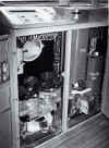
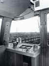 So far,
we have not looked at starting and motoring for the ATO system. Cab equipment is
shown in Fig. 9 (left).
So far,
we have not looked at starting and motoring for the ATO system. Cab equipment is
shown in Fig. 9 (left).
Click on the image for the full size view and description.
When the driver (sorry, Train Operator) is ready to leave the station and closes the train doors, a number of things must be in place for him to be able to start the train.
1. A pair of start buttons on the control desk must be operated.
2. Doors must be closed.
3. Cab side droplight must be closed.
4. The door control contacts must be "off’.
5. There must be a 420 code on the track telling the train it is safe to proceed.
Once the driver presses the start buttons, activation of the traction control train wires (to allow the train to motor) is routed via a special feed relay, which must be energised before the train can leave the station. The relay will not drop out until it is cancelled by a station brake command. This is necessary in case there is a signal stop between stations. When it is safe to restart, we want the train to remotor without the driver having to press the start buttons again. Because the feed relay remains energised, a subsequent 270 code will cause the motors to start up again automatically.
To the Top of this Page
One of the enhancements of the RADB was the inclusion of ATO system data logging facilities. Information related to the operation or malfunction of the RADB and the ATO System is captured whenever the train is running in automatic operation. One may safely assume from this that any instances where the driver uses manual driving will be recorded. Of course, the log will also record faults, overruns etc. so unlike the original system, there is some record of intermittent defects.
To the Top of this Page
The Central Line also uses ATO over most of the line and ATP along the whole line. If you would like information on the technicalities of the Central Line ATO system, which is quite different from the Victoria Line system, try The Central Line Signalling System - Clive Feather's excellent technical description of the Westinghouse ATP system.
Victoria Line Track & Signalling Diagrams
To the Top of this Page or to the Home Page This page upgraded 15 March 2003 Copyright © Tubeprune 2001, 2002. If you have comments or if you would like to use any part of this site for publishing or commercial reasons, please e-mail me |


