Automatic Signalling on London Underground
This is the first page of a series on LU
signalling. It is a description of the automatic signalling used on London
Underground. Links to other the other signalling pages are listed in the column on the
left.
Contents
Basics - Automatic Signal Operation - How Automatic Signals Work - Overlaps
- Multi Home Signals
Railway signalling is based on a simple principle for keeping
trains a safe distance apart. The principle is that a line is divided into sections
called blocks and only one train is allowed into one block at one time. Each block
is protected by a signal at its entrance. The train driver approaching the signal
responds to its stop or go indication and either stops the train at the signal or proceeds
into the block accordingly. The locations of the block boundaries are fixed
("fixed block" signalling) and so are the signals. The signalling on
London Underground is based on this fixed block system. This is used on all lines
including the Victoria and Central Lines, which use also ATO (Automatic Train
Operation). More on the Victoria Line ATO system
here.
Each track is divided into sections ranging from a few metres
to a few hundred metres long. The average length is about 300 metres. The
entrance to each block is protected by a colour light signal (we are referring to non-ATO
lines here). To prevent a train proceeding at normal speed
into an occupied section, each signal is provided with a mechanical "trainstop"
adjacent to the track. By means of a trip arm on
the train, the trainstop will apply the brakes of any train which attempts to run past
a stop signal.
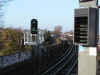
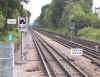 The photo on the left (Fig.
1) shows a typical arrangement of an automatic signal and trainstop. The photo on the left (Fig.
1) shows a typical arrangement of an automatic signal and trainstop.
Click on image for full size view
The trainstop is lowered when the signal shows a clear
(green) aspect. Compressed air is used to lower the trainstop against the spring
pressure used to raise it. This provides an element of fail safe, should the air
supply be lost. The air is compressed in the traction sub-stations and is
distributed alongside the track in an air main. This can be seen as the silver pipe
in the photo above supported on posts at the track side, together with the signalling and
power cables.
To the Top of this Page
Each block is equipped with a "track
circuit", a low current circuit passing through the running rails. This
is used to detect the presence of the train. The circuit is arranged so that if it
fails, the signal will show a red aspect. Track circuits failures and other spurious
red indications are the principal cause of "signal failure" announcements so
common these days.
Track circuits were first introduced to the UK in 1903 on the
Ealing and South Harrow Railway, now part of the Piccadilly Line branch to Rayners
Lane. The system was imported from the USA, where it had been tried on a number of
densely used routes. The track circuits in adjacent block sections were isolated
from each other by cutting the rails at the ends of the block and inserting insulated
joints. These became known as "insulated block joints".
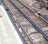 Fig. 2 on the left shows the insulated block joints in the running
rails at the end of a block section. Note the raised trainstop on the right hand
side of the track acting with a red signal (not seen here) to protect the entrance to the
next block. Fig. 2 on the left shows the insulated block joints in the running
rails at the end of a block section. Note the raised trainstop on the right hand
side of the track acting with a red signal (not seen here) to protect the entrance to the
next block.
Click on image for full size view
Insulated block joints are a constant source of
weakness in that they are prone to failure under intensive use. In the last ten
years, London Underground has been replacing the old track circuits with new ones which do
not require block joints to separate them. These are known as "jointless track
circuits".
To the Top of this Page
The following diagrams show the basic operation
of automatic signals on London Underground. Automatic signals are identified by a
number preceded by the letter A, e.g. A123. As long as the block it protects is
clear of trains (and everything is working properly) the automatic signal will remain
green (Fig 3 below).
Fig. 3: Diagram of automatic signals
positioned to protect the entrance to block sections. Note the signals are
identified by the A prefix and are numbered like houses, odd numbers on one side and even
numbers on the other side.
When a train enters the block, the presence of the train is
detected by the track circuit and the signal automatically displays a red aspect as shown
below.
Fig. 4: Diagram showing how the signal aspect changes
as a train enters a block (Block 2). Remember that the signal has a trainstop which
rises when the signal changes to red.
The signal will remain red all the time the train is in the
section. When the train enters the next section (shown below Fig 5) the signal
protecting that section will also change to red.
Fig. 5: Diagram showing the aspect change
of signal A125 as the train enters the second block. The signal (A123) protecting
the first block is still showing a stop aspect because part of the train is still in Block
2.
To the Top of this Page
The system so far described shows a simple form of train
protection but, in reality, it is more complex. See what happens if a train stops
just past the entrance to the block, as shown in the next diagram.
Fig. 6: Diagram showing a second train
approaching signal A125. If Train 2 fails to stop at A125, there is not enough room
beyond A125 for the train to stop before it hits the first train standing just beyond the
entrance to the block.
The train stopped just inside Block 3 is protected by Signal
A125, but only if the second train stops at the signal correctly. Should it run past
the signal, it will get "tripped" by the trainstop of A125. However, there
is insufficient room for the train to stop before it collides with the first train.
The safe braking distance is too short. To overcome this situation, each signal is
moved back a safe braking distance from the entrance to the block. This distance is
called the overlap as shown in Fig 7 below.
Fig. 7: Diagram showing how overlaps are
provided for signals by placing them a safe braking distance from the entrances to blocks.
The overlap now provides a safe braking distance for any
train which overruns a signal so that there is no risk of it colliding with a stopped
train in front. Very clever but this arrangement creates a difficult new situation, as
shown in the next diagram below.
Fig. 8: Diagram showing how a train
standing in the overlap of a signal can be in a position with a green signal showing
behind it.
Because the overlap has to be of sufficient length to allow a
train travelling at normal speed to stop, it can be longer than a train's length.
This could result in a train standing ahead of a signal but that signal would be showing a
clear aspect. Although, in our diagram, the train is still protected by signal A123,
it is not considered safe on London Underground to allow a green signal to be displayed
behind a train. Overlaps are therefore track circuited separately and coupled to the
block ahead (in this case, Block s) and would therefore ensure Signal A125 shows a red
aspect as shown in Fig. 9 below.
Fig. 9: Diagram showing how the inclusion
of overlap track circuits provides protection for a train standing in the overlap of a
signal.
The effect of providing overlap track circuits and
coupling them to the block ahead is that the train has two signals protecting it.
There is always a safe braking distance beyond a red signal for a train standing in any
location.
 A set of
photos (see icon on the left) shows how the sequence of automatic signals works as a train
passes from one station to another. A set of
photos (see icon on the left) shows how the sequence of automatic signals works as a train
passes from one station to another.
Click on image for full size view
To the Top of this Page
The biggest constraint on throughput for a rapid
transit railway like the London Underground is the time spent in stations. Trains
run at frequent intervals (or at least they should) so they are close together. It
follows then, that if a train waits in a station too long, the next train will be delayed
and no amount of fancy signalling will help matters. However, there are some things
which can be done to reduce the delay to a following train if the dwell time in the
platform is likely to be longer than normal. One of these is to install multi home
signalling.
Traditional station signals are laid out as
shown in the diagram below.

Fig. 11: Diagram of the standard station
signals showing the location of the full speed overlaps for each signal.
In this arrangement, if a train approaches the
station home signal, A123, at normal speed and fails to stop, the overlap is of sufficient
length to allow it to stop before reaching the train in the platform. If it does
stop normally at the signal, it will have to wait for the train in the platform to leave
and clear the overlap of signal A125. However, some time could be saved if the
second train could be allowed to approach the platform once the train in front has started
to leave. One way of doing this is to shorten the overlap of Signal A125.
Fig. 12: Diagram of station signals
showing the short overlap for the starting signal A125.
In Fig. 12, the overlap of A125 has been reduced
to a few metres. Reducing the length of the starting signal overlap allows the
signal in rear (A123) to clear sooner so that the next train can run into the platform a
few valuable seconds earlier than it could if a full speed overlap had been provided.
However, the shorter overlap on the starter
signal represents a reduction in safety because there is insufficient braking distance
should a train run past the signal at full speed. However, this is unlikely, since
most trains will be slowing for a stop at the station anyway. In case a train has to
run through without stopping, a rule (nowadays enforced by a time delay system on the
starter at many places) restricts all trains to 5 mi/h when running non stop through
stations where they are normally booked to stop.
A further reduction of the time spent waiting at
a home signal for a train to clear the platform can be achieved by the use of multi home
signals. This is done by installing additional signals and additional track circuits as
seen in the next diagram.
Fig. 13: Diagram of multi home signals
showing the additional signals and track circuits required.
When the train in the platform starts to leave
and moves forward to clear the first track circuit at about one-third of the platform
length, Signal A123a will clear. At the second track circuit clearance point, at
about two-thirds of the platform length, A123b will clear (Fig. 14 below). A123c
will clear as the train clears the overlap of signal A125.
Fig 14: Diagram of multi home signals
showing how a second train approaches the platform as the preceding train leaves.
By the use of multi home signals, a following
train can approach an occupied platform as the train ahead leaves, as shown below and
several valuable seconds are saved. Multi home signals are in use in many places all
over London Underground, especially in the central areas where train frequencies are
highest.
|


