Adding lights and Interior to an Aristocraft Bobber Caboose
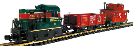
For Christmas 2003 I bought a Lil' Critter Christmas Starter Set to run on the WGR Overhead division. After I bought it, I thought it would be nice to add lights and interior detail to the bobber caboose included with the set. I did some initial measuring and determined that one of the lockers that made up the interior of the Aristocraft Long Steel Caboose could fit in the bobber caboose and be used to add lights.
The right hand locker of the long steel caboose has two light bulbs mounted on either side of the locker. So I ordered the following parts from Aristocraft:
42100-36 - R.H. Locker
42100-50 - Light Bulb Holder
I also ordered some additional parts from a online retailer to complete the interior of the caboose.
29123B - Ball Bearing wheels with power pickup - Blackened
29503 - Light Bulbs and Sockets
29700 - Chairs for Long Steel Caboose
29701 - Interior Kit - Long Steel Caboose (This includes the following items)
Desk
Water Can & Sink
Cot (2)
Commode & Lid
Coal Box
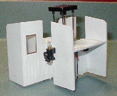
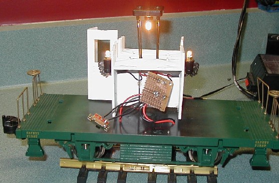
When I received the parts from Aristocraft they included far more than the right hand locker. They included both the right hand locker, light bulb holders, light bulbs, wiring, left hand locker, right and left hand grab irons, and the cupola light assembly. I don't know if they would be this generous if I did another caboose, but I'm not complaining.
This worked out very well, since both lockers and the cupola light will fit in the bobber caboose with only some minor cutting. The whole assembly fits width-wise in the caboose, the lockers are just too tall.
So, now I got started on fitting the lockers into the caboose.
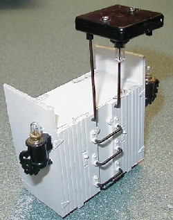
First I cut off 5/8" off of the tops of the right hand locker assembly so that it would fit into the caboose. For the left hand locker I cut 5/8" off the walls on either end of the locker. The walls of the water closet only had to be trimmed about 1/4" since they fit up into the curved roof area of the caboose.
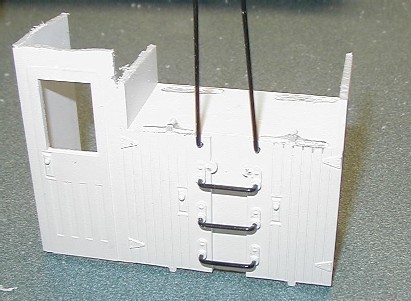
I also cut off the tabs on the bottom of the lockers that were used to mount to the floor of the long caboose and trimmed the bottom of the right and left hand grab irons that support the cupola light . This lets the lockers set flush with the floor of the caboose.
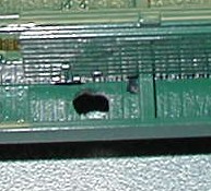
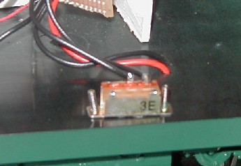
I placed the lockers on the the bottom of the caboose and marked the foot print of the lockers. I then drilled a hole from the bottom of the caboose inside the footprint of the right hand locker where the wiring for the lights is located. This is where the switch for the lights will be located to allow the lights to be turned on and off.
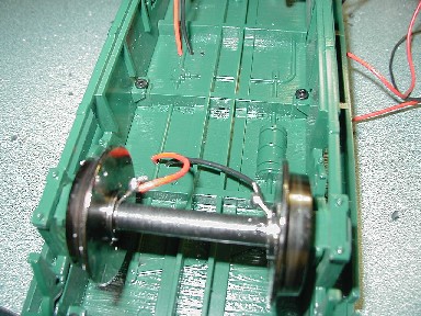
I replaced the plastic wheels that came on the caboose with Aristocraft blackened ball bearing wheels with power pickup (Aristocraft part # 29123B).
I then drilled two holes on each end of the footprint of the right hand locker to pass the wires from the wheels to the inside of the locker. I then soldered wires to each of the power tabs of the wheels.
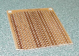
To make all of the wiring connects I bought a multipurpose printed circuit board (PCB) from Radioshack (Part # 276-150). I had to cut the PCB to fit within the right hand locker. I just used a pair of wire cutters to snap the board where I wanted.
Once the connections from the lights were wired to the PCB, I connected the red wires from the wheels to one connection from the lights on the PCB. Next I wired the black wires from the wheels to the PCB. I then wired a SPST switch from Radioshack (Part # 275-406) to connect the black wires from the wheels to the second connection from the lights to the PCB. I then tested the lights.
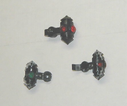
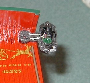
Now I moved on to adding illumination to the marker lights on the rear of the caboose. I first removed and then pried apart the two halves of the marker lights as shown below. If you look closely the front half of the marker light (the half with the green lens) already has two grooves and two holes through the bracket already which can be used for running wire to a lamp. I enlarged the groove slightly so the 28 AWG wire I would run to the lights would fit in the groove.
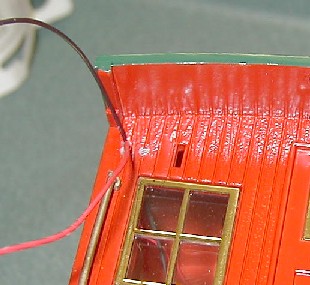
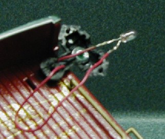
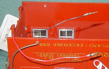
I drilled two 1/16" holes through the back wall of the caboose on each side where the wire would pass through the front half of the marker light.
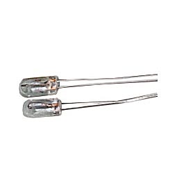
I bought two 12V microlamps from Radioshack (Part #272-1092) to use in the marker lights. I soldered 28 AWG wire to the first microlamp and fed the wire through front half of the marker light and through the drilled holes into the interior of the caboose. Since the microlamps were rated for 12V, and since the Crest 55401 controller outputs 21V, I wired the microlamp for the second marker light in series with the first to reduce the voltage across each lamp. After soldering the lamp to the wires, I pulled the excess wire back into the caboose.
Since there would be wiring between the underframe and the caboose body, I wanted to put connectors between the body wiring and the locker lights. This would allow me to completely separate the caboose body from the underfame. I liked Geroge Schreyer's idea of using D-sub connectors that he documented on his Power Connector Tips web page.
I got the D-sub connectors by buying at Radioshack a 25-Position Male Solder D-Sub Connector and a 9-Position Female Solder D-sub connector. I would have bought a 25-Position Female connector but they were out. I then pried apart the connector with vise grips to removed the pins. This gave me 25 male pins for $1.89 and 9 female pins for $1.59.
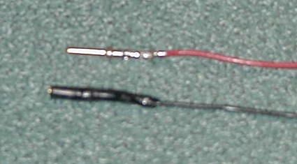
I then soldered 1 male and 1 female D-sub connector to the two wires coming from the marker lights.
Next I soldered 1 male and 1 female D-sub connector on two more wires. These wire I soldered to the PCB.
I then used heat shrink tubing over the D-sub connectors and solder connections.
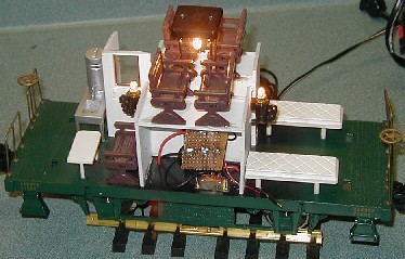
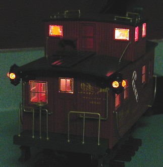
Finally I tested all of the lights together. The lights were a little too bright for what I liked, so I wired a 10 Ohm resistor is series with the lights to dim them a bit.
With all the wiring done, I moved on to fixing the pieces into the caboose.
I placed the switch on the underframe and marked the location for the two holes to mount the switch. I drilled two 1/16" holes through the floor of the caboose. I painted the heads of the screws for the switch dark green and then secured the switch to the caboose floor.
I hot glued the wires in the body of the caboose to the ceiling and sides.
I cemented the lockers to the floor of the caboose.
I cemented the halves of the marker lights back together.
Once the lockers where secured, I placed the caboose body back on the underfame. Unfortunately, it didn't fit! When I had measured the amount to cut on the lockers I had measured the length of the lockers protruding beyond the side of the caboose body. However, the side of the caboose body extends down and covers the side of the underfame. So I needed to cut more from the walls of the lockers and water closet so the caboose body would fit. The final height of the locker walls was just under 2 3/8" and the final height of the water closet walls was just under 2 3/4". The caboose body then fit, barely and snapped to the underframe. The locking tabs that hold the cupola to the caboose body were just touching the tops of the lockers, so I filed these down a little so the would not prevent the caboose body from locking onto the underframe.
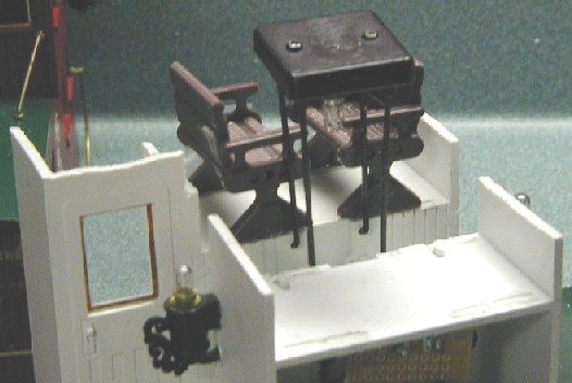
I then worked on adding the chairs to the interior of the caboose. I first checked to see if the chairs for on top of the lockers would have enough clearance. I had to position the chairs a little closer together than they are in the long steel caboose since the cupola is smaller on the bobber caboose. There is a tab on top of the lockers that is used for positioning the chair. I had to file these off in order to put the chairs closer together. I then cemented the chairs to the top of the lockers.
I also added chairs and portions of the long steel caboose interior kit to the caboose. In order to make the cots fit, I cut 3/16" off of one end of each cot. .
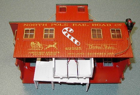
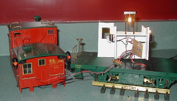
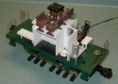
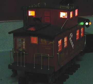
Finally I replaced the caboose body onto the underframe. .
So what did this cost me to construct? Here's what was used and how much
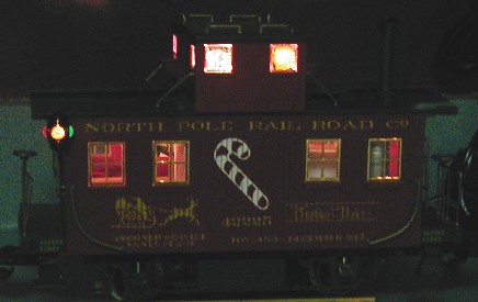
it cost. It was a fairly high expense to add to a bobber caboose, but I was very pleased with the outcome and I think it adds a lot to the train. Once the whole train is out for the Christmas season, I will add a picture of the train running with the lights.


 .
. 
 .
. 


