


| Home | History | Layout | Construction | Roster | WGR Halloween | Tech Tips | Links |
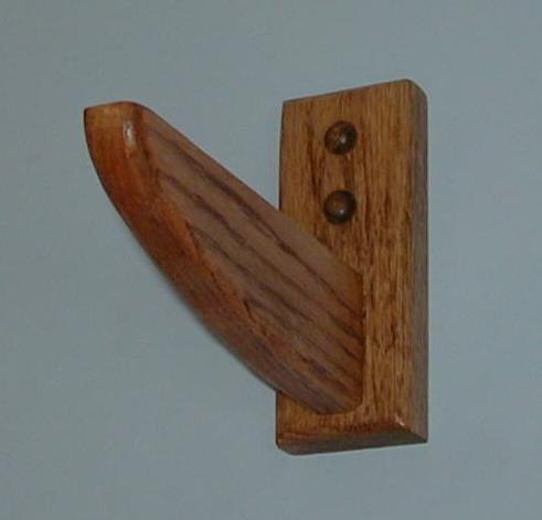
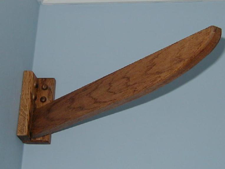
My dad had been working on the shelf supports for the overhead line. He arrived with sixteen brackets for the straight sections and four corner brackets already stained and finished. He made them from scrap oak that he had left over from various projects. We went to Lowe's and bought a 4x8 sheet of oak plywood, and 3/4" iron on oak veneer to finish the inside edge of the shelf.
We first cut four 3 3/4" straight sections from one side of the sheet of plywood. Then using the 4' curve as a template, cut four corner pieces with a 4" straight section on both ends of the curve. Next we cut a groove down the center of each piece to lay wire if necessary. I don't have any current plans for it yet, but it could be used to run wire for sensors to implement a station circuit.
A clothes iron was used to apply the oak veneer to the inside edge of all of the shelf pieces. Minwax provincial stain was used to stain all the pieces and Minwax aerosol satin finish was used to protect the wood. To the left is a picture of all of the pieces drying.
Next we started hanging the brackets to hold the shelf. We held a level to the crown molding to verify that it was level. Since it was close we did not bother with snapping a chalk line to make sure the brackets were lined up. We simply measured down from the crown molding for a reference. We used the opening from the foyer as a reference to determine how far down the wall to position the brackets. By positioning the top of the bracket 6 5/8" down from the crown molding, the bottom of the bracket was flush with the opening from the foyer. This placed the top of the support for the shelf about 11 1/2" inches down from the ceiling. With adding the 3/4" for the plywood, this left about 10 3/4" clearance from the ceiling. The C-16 and Sierra cars with the height of ties and rail needed slightly under 8" clearance.
We started by mounting two corner brackets. The brackets are made so that it will be held by two screws into each wall at the corner. We marked the wall using the bracket so we could drill pilot holes into the wall. On the first bracket we only hit a wall stud on one wall. On the second wall we had to use drywall anchors to mount the bracket to the wall. With the second corner bracket we did not hit a stud on either wall so we used the anchors on both walls. Where he did hit studs we used #8 x 3" wood screws to attach to the wall. 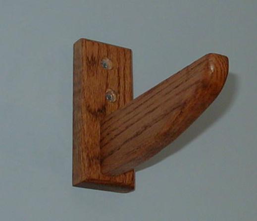
After mounting the first two corner brackets we started mounting the brackets along the wall by the foyer. Ideally we would mount the brackets in wall studs and 28 1/2" to 32 1/2" from the corner. This way they would be well supported and would support the straight section on either end of the corner shelf pieces. As it turns out we met both criteria on the foyer wall. It also helped that the opening to the foyer was close enough to one corner we were able to mount the bracket in the header for the opening. To mount the remaining to brackets on the foyer wall we split the difference between the to brackets near the corners, since the remaining two brackets would be mounted to the wall where the header for the opening to the foyer is.
All the brackets have the holes for the screws counter sunk to that the screws can be hidden by wood buttons.
The next wall was the front wall over the bay window. We mounted the third corner bracket and then proceeded with the brackets along the front wall. Since the opening for the bay window was taller than the foyer opening I had to extend the wall brackets down below the top of the opening by about 2" to maintain a level shelf. Two brackets we mounted just to the outside of the bay window opening. This was close enough to the corner to support the corner pieces. The last two brackets were evenly spaced and mounted to the header over the bay window. I had to shim that backs of these two brackets so keep them aligned with the others since the wall was was not quite vertical over the bay window. 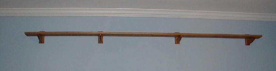
We then continued along the last two walls. Three of the four corner brackets we able to use screws into studs on one wall and drywall anchors on the other wall. The fourth had drywall anchors on both walls. This was not ideal for support but I will see how it goes. If the brackets seem to be loosening in the wall I will have to see about supporting the brackets from the ceiling. We were also fortunate that we only had to use the drywall anchors on one bracket along a wall to maintain a reasonable spacing.
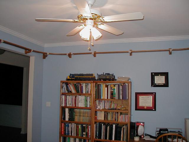
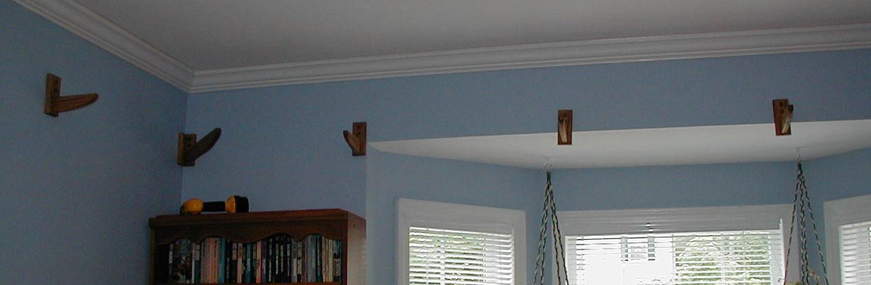
Once all of the brackets were mounted we set the shelving on the brackets to get a preliminary look at the room. We ran out of time to continue this weekend. The next step will be to use a biscuit cutter on the shelf pieces so that they can be joined with a strong joint. I will post more pictures as the project continues.
I began at one corner. I used a biscuit cutter to cut the slot on both ends of the corner piece. I then used masking tape to hold the corner piece down to the wall brackets. I did the same for the corner piece for the opposite corner on the same wall. Next I took a straight piece and cut the slot for the biscuit in one end. I then butted the end of the straight and corner piece with the biscuit inserted to hold the pieces level with each other. I then placed the other end of the straight piece on top of the second corner piece and using a pencil on the underside of the straight piece to mark where to cut. I then cut the straight piece using a circular saw with a plywood blade and cut in the direction so that the saw cut into the underside of the shelf to minimize splintering on underside of the shelf. The straight piece was then placed up on the brackets the fit together with the first two corner pieces. The straight piece was then tacked down with masking tape.
Next I continued to the second wall. I took the third corner piece and used the biscuit cutter to cut the slots in the corner piece. It was tacked down the the wall brackets with masking tape. The second corner piece was then slotted with the biscuit cutter on one end and set into place against on the second corner piece and resting on the third. A line was then drawn to mark where to cut. The second straight piece was then cut to length, slotted, and fit into place.
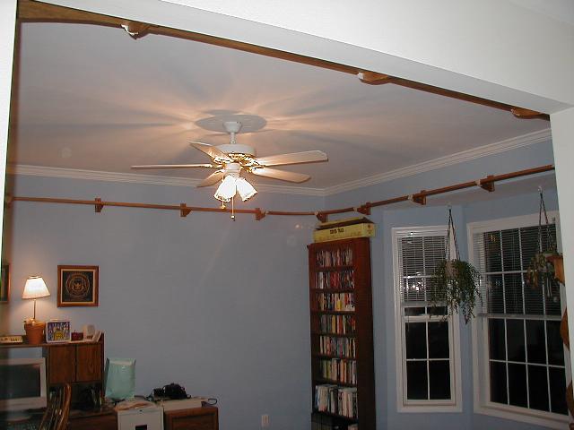
The third and fourth walls were completed in the same manner as the second. To the left are two pictures after all the cutting and fitting were completed. The masking tape is still in place since the shelving in not secured down.
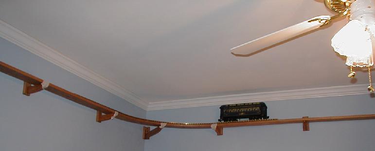
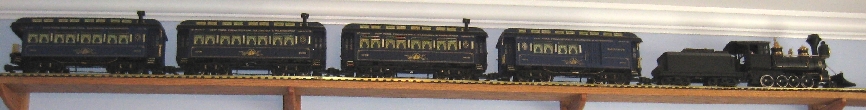
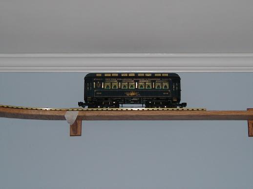
After all the pieces were cut and fit into place, a small section of track was laid on one corner of the shelf to get a preliminary view of the shelf with the track. One Sierra passenger car was set on the rail. The car had no problem with clearances on the corner so I guess I planned it out and measured correctly. Next will be to get the rail and cut to fit. More pictures will be posted as I continue.
So I took down two corners and two straight pieces. I sanded the finish off the back edge and glued the veneer to the edge. I then stained the new veneer. I will then have to spray the finish on the new edge. Once this is done I will move on to cutting the rail.
I have sprayed the finish on the newly added veneer. Since I had the shelving taped down onto the brackets I decided to begin fastening the shelving down. I began in one corner by marking on the bottom of the shelf where it rested on the brackets. I then took the shelf down and drilled a hole large enough to allow a #6 screw to pass through. I Then repositioned the shelf on the brackets and drilled a pilot hole into the brackets for a screw. I then screwed the corner piece to the brackets to secure it. I then moved onto on of the adjoining straight sections of shelf.
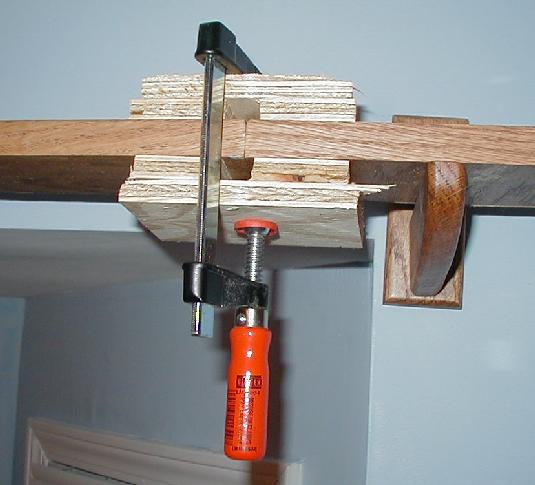
I again positioned the shelf on the brackets and marked the underside. I drilled the holes through the shelf, positioned it on the brackets and drilled pilot holes into the brackets. I then spread glue on the end of the curved section already secured and the current straight section. I also put glue into the slot cut for the biscuit and the biscuit itself. I then pressed the ends of the two sections together and clamped them down as shown in the picture to the right. By clamping it this way I ensured that the shelf pieces remained aligned put had nothing in contact with the glued joint itself.
I then moved onto the next curved section and proceeded the same as I did with the straight section. I got three curved and two straight sections completed tonight. I will try to complete the remaining sections tomorrow.
Today my Dad and I started with laying and cutting the rail. We started by taking two complete corners of track and attaching one straight section on either side. In this way we could make sure the curve was oriented on the shelf correctly. Each straight section of the room was between 7.5 and 8.75 feet long so three 3 foot sections were enough to complete a side. We laid the third section on top of the two adjoining the curves to mark the rail for cutting. To cut the rail I used my Dremel tool in the drill press attachment with the right angle attachment to get a good square cut on the rail. We put the newly cut section into place to verify a good fit. We then assembled another curved section so we could mark and cut the piece for the next straight section and checked it fit. We did the remaining two straight sections in a similar fashion.
We then took each cut section down and I used the Dremel in the drill press to drill the holes for the track joiner screws. I then used a tap to cut the threads for the screws. We then assembled the straight sections to complete one side and the curved section leading to the next straight section. We attached the track down to the shelf with #6 x 3/4" pan head screws. The plastic ties and plywood were soft enough I could just screw the track down without drilling any holes.
We drilled, tapped, and fastened the the next two straight sections and curves without any problems. When we got the the last straight section we hit a snag. The last cut section of track was too long by about 1/2". I figure that when we were positioning the track to mark it to cut it shifted at various points. This wasn't too much of a problem since the piece was too long. We simply marked the piece again and cut , drilled and tapped it for the holes and fit it into place.
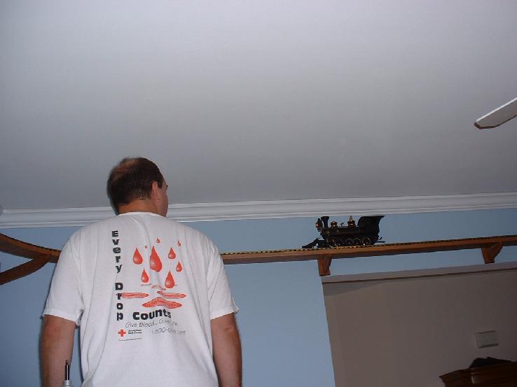
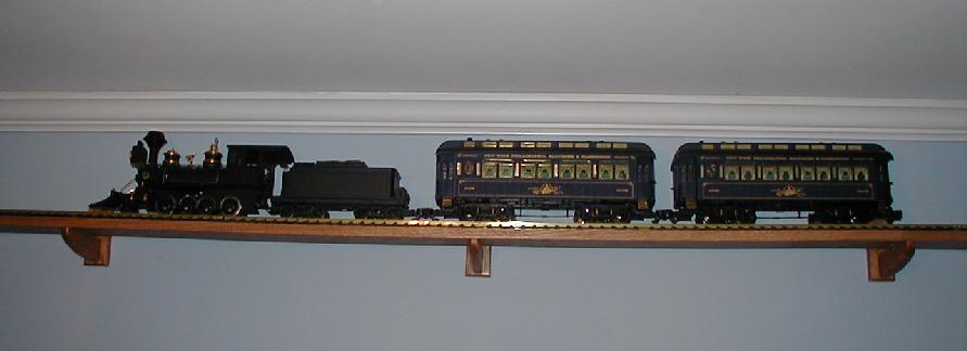
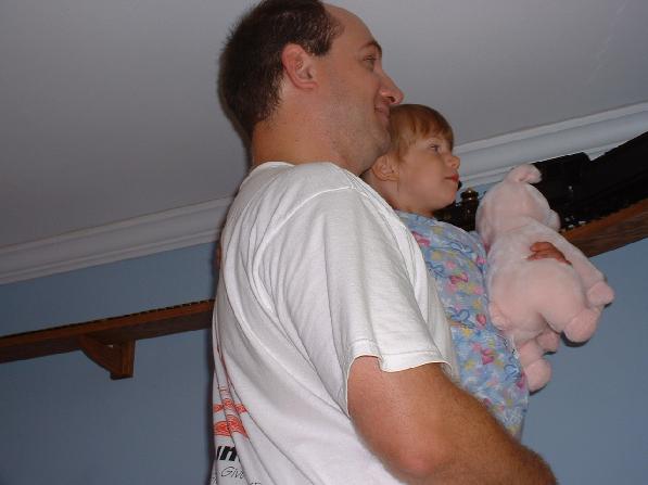
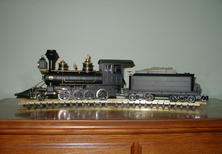
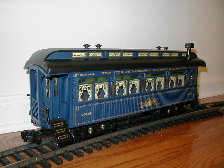
Finally we were ready for a test run. I first took one of the Sierra passenger cars and ran it around the track a few times to look for major problems. It seemed to roll fine. Next I hooked up the power to the track. I ran the same car around again. I didn't notice any flickering in the lights, so the electrical connections seemed good. So I got out the C-16 and put it on the track. I ran it around slowly a couple of times. The pony truck would derail on on one section of curved track in both directions. It was not out of level, so I took it down for inspection. It didn't seem too be out of gauge by a quick inspection although the railhead itself looked slightly narrower. It was the middle section of three in the curve so I swapped it with one of the others in the curve. After reassembling the track I ran the C-16 around again. The pony truck would derail on the same section if it entered the section while already on the curve. However, it was fine if it entered the section from the straight. So for now I will run the engine in that direction. Finally I attached the tender and Sierra cars. It looked great running around the room. The kids enjoy watching it run around the track. I even gave them a close up view before the ladders were put away.
Next I will have to run the wire up inside the wall so that I don't have a wire hanging down from the shelf to the desk.
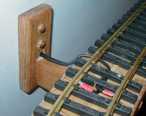
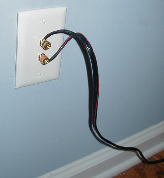
I ran the wire through the wall last night. So it is no longer hanging down from the shelf. I drilled a hole through one of the support brackets into the wall. There was one bracket that was not on a stud so I was able to drill directly through the bracket into the wall between studs. I then cut a hole for a single gang box near the floor at the same height as the electrical outlets. I pulled the wire through the hole into the box and secured the box to the wall. I then attached the wire to a speaker terminal wall plate and screwed the wall plate to the outlet box. I then pulled the wire from its old location and attached it to the speaker terminals.
So what did this cost me to construct? Here's what was used and how much it cost.
Item Cost 8' x 4' x 3/4" oak plywood 39.99 3/4" x 25' oak veneer 3 @ 5.92 Minwax stain 4.84 Minwax satin spray finish 4.94 3/8" hollow wall Anchors 6.63 #10 x 3" (20 ct) wood screws 2 @ 5.92 Titebond II wood glue 1.98 #6 x 1" (100 ct) wood screws 2.24 #6 x 3/4" (100 ct) pan head screws 2.24 single gang box 1.58 wall jack with binding posts 12.86 16 gauge outdoor lighting wire 6.86 #20 bicuits - donated 8 @ 0.00 solid oak for brackets - donated 20 @ 0.00 Sub Total 113.76 Sales Tax 7.96 Total 121.72
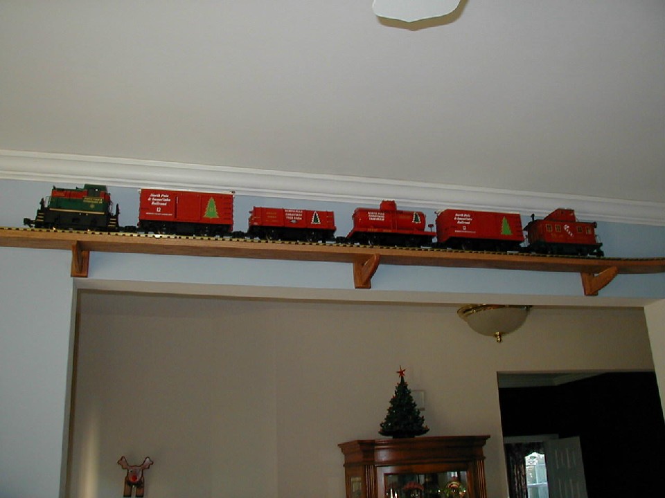
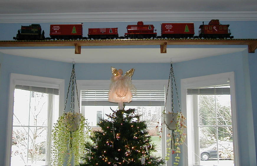
The first season of Christmas Division on the WGR overhead has commenced. The Lil' Critter starter set with the additional cars has begun running on the overhead line. The 20' gondola, tank, and box cars have been equipped with metal wheels. In addition the bobber caboose has been outfitted with ball bearing metal wheels with power pickup. The bobber caboose has been upgraded to have interior lighting as documented here.
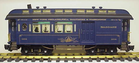
I received a B&O Sierra Combine for Christmas. I now have four Sierra Passenger cars running on the overhead line.
This page last updated January 25, 2006


