INDUSTRIAL, OFFLINE
TERMINAL RAILROADS &
RAIL-MARINE OPERATIONS
OF BROOKLYN, QUEENS, STATEN
ISLAND, BRONX &
MANHATTAN:
Development of the Carfloat
Transfer Bridge in New York Harbor Jersey pontoon float railroad rail marine
ferryapron French Bensel Mallery NYNJ Rail Pennsylvania Haven
Hartford Baltimore Ohio Central Long Island Oak Point Brooklyn Queens
Bronx Staten Island
Manhattan Harsimus Greenville Weehawken Hoboken Claremont Hell Gate Bay
Ridge NYNH&H LIRR PRR NYC West Shore Hudson River
East
.![]() .
.
www.transferbridgesofnyc.info
| updated: TUESDAY, 07 May 2024 - 15:45 |
||
|
|
||
| the 1970 LIRR Bridge 5 collapse | 07 May 2024 | LIRR LIC Transfer Bridge 5 Collapse of 1970 |
| photo of a LIRR steam locomotive on a transfer bridge | 06 May 2024 | A Popular Misconception |
..
.


.
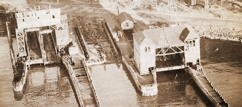
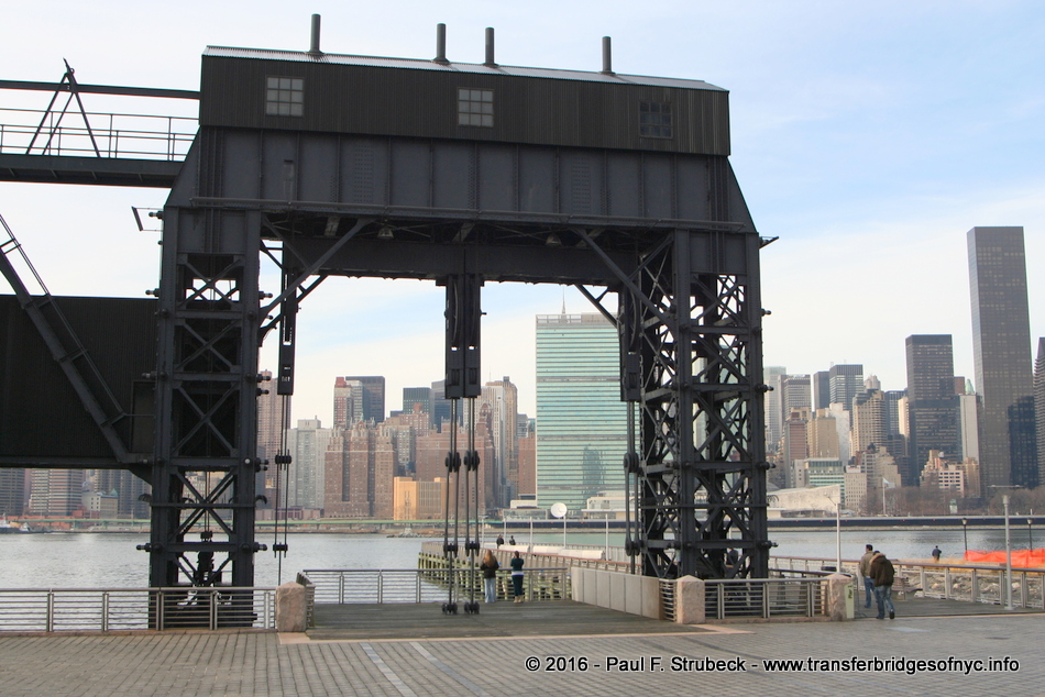
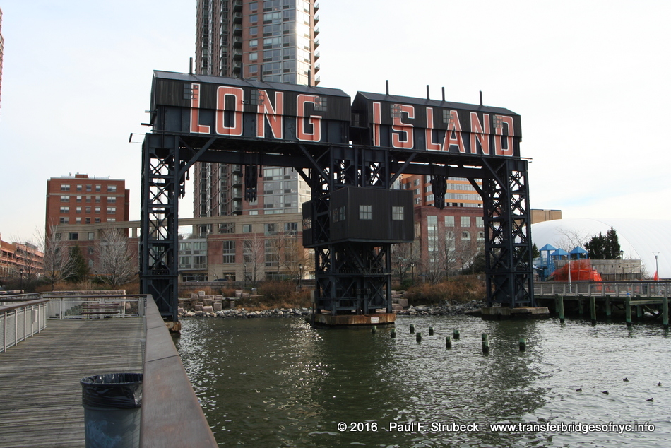
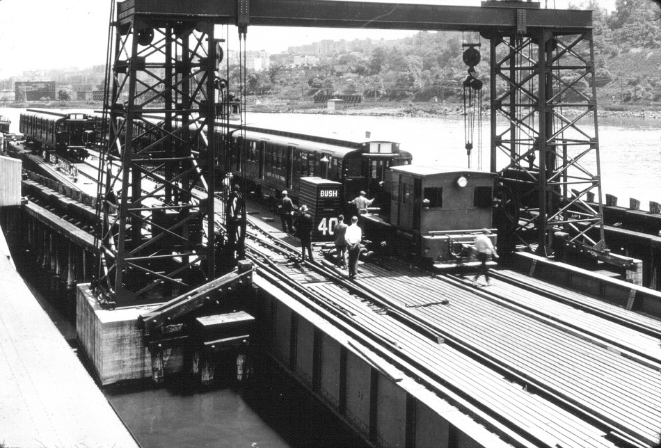
Three types of transfer bridges in one location: New
York Central Railroad West 60th Street Terminal, Manhattan, NY - 1978
| left: electrically
operated Overhead Suspension Contained Apron "J. B. French patent" center: Pontoon / Steel Pony Truss right: electrically operated Overhead Suspension Separate Apron "J. A. Bensel patent" |
T. Flagg
photo
added 04 January 2012
.
.
|
Readers please note:
Furthermore, the terms used on this page were
those used in New York Harbor float / transfer bridge operations, |
.
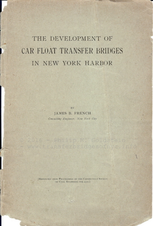
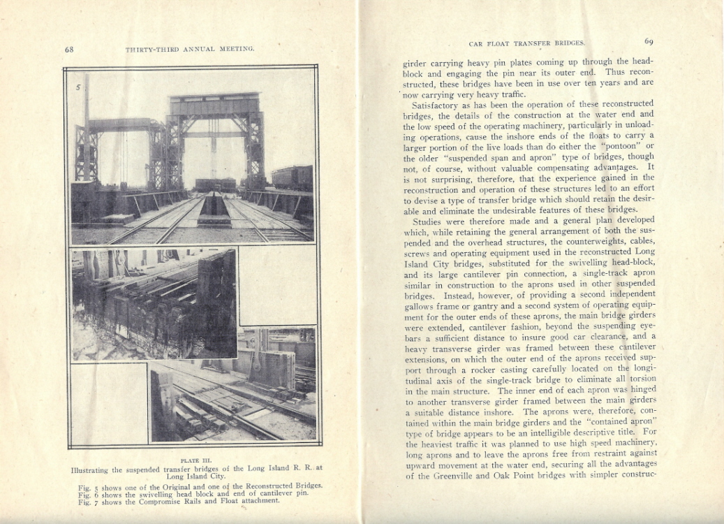
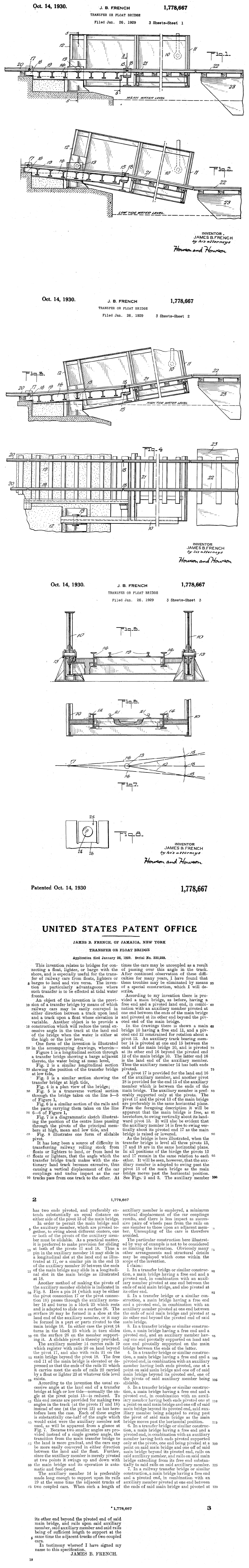
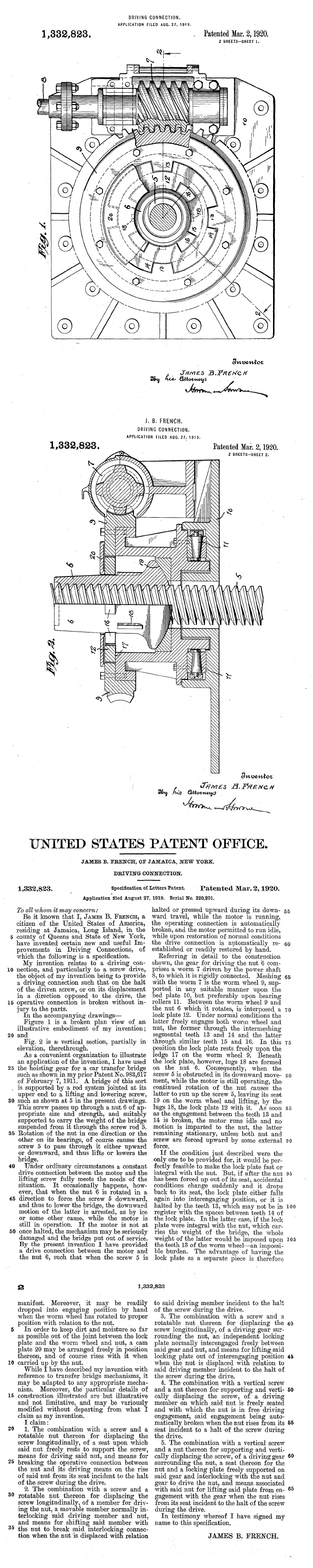
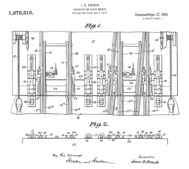
If the title of this page sounds familiar, that is because James B. French's benchmark book of 1917 bears the same title. Sometimes, you just can't come up with a better title than that used before! However, where as French's book primarily covered the development of his contained apron design, this page will encompass all the various designs of float bridges as that information is encountered.
The information on this page was originally located on the main page of this website. It was brief and concise for the intent of giving the novice reader a basic understanding of the methods and technology used for rail-marine operations.
As with anything on this website, what started out with the most basic of information turned into a work of great magnitude, as should be with all good things of interest. Further reinforcing the expansion of this information, was that it was determined that more than just the novice reader was known to have referenced this information. So little by little, more and more diagrams, illustrations and detailed information were added. On top of which, I had purchased an original of J. B. French's 1917 book on the Development of the Carfloat Transfer Bridge in New York Harbor some time ago, so I had scanned it and included it on the main page to share with the rest of those interested parties.
Following requests by readers for better & larger scans, I re-scanned the book. Then on 31 December 2011, Paul Strubeck located illustrations and the patent filing of the Mallery "Swiveling Head Block" type transfer bridge bridge as well as illustrations and patent filing for J. B. French's "Contained Apron" type, both of which in turn was the inspiration for creating this dedicated page to transfer bridge histories.
As a result, the section of transfer bridges grew longer, and took even more time to open. So, it became obvious this information would need to be relocated to its own page. Then came the next obvious decision: to solicit Tom Flagg to join us for the expansion. Tom's interest in industrial archeology has led him to amass an extensive amount of plans, images, and documents on the subject of transfer bridges. And, as he had already published some of this information on transfer bridges, most notably his feature length articles which were published in four parts in Issues 12, 13, 15 & 23 of the Rail Marine Information Group's periodical publication "Transfer"; it was only logical to ask him to join us.
Tom granted his whole hearted and enthusiastic approval and
so, it became our goal to combine on this page in one easy reference:
All of Tom's feature length articles, his general information in his New York Harbor Railroads books, both of these subsequently updated on this page with known information since the original publication dates of those articles;
With those of the older published articles such as the: 1888 Bensel / American Society of Civil Engineers Discussion, 1901 Railway Age, 1903 Mallery Patent filing, 1905 Railway Age, 1911 French Patent filings, French's 1917 book on the Development of the Carfloat Transfer Bridge, among many others;
As well as any other contemporary informational sources as we acquire them, published or discovered after Tom's original publishing in "Transfer".
The four recognized parts of Tom's series: "Overview & Pontoon", "Separate Apron", "Swiveling Head Block and Contained Apron", and the "Recap", have been reorganized. The corrections and further explanations as noted in the recap (Part IV) have been integrated into their respective areas, and the "Swiveling Head Block" and "Contained Apron" chapters were split from one published article into two separate chapters.
Furthermore, not having to deal with the space restrictions of a one or two page spread in a standard bound and printed book or periodical, we are able to use much larger images and illustrations here.
I wish to make it clear, that despite our re-publication and reformatting of Tom's articles as they originally appeared in those four issues of Transfer, it is highly recommended that you still purchase the back issues (digital) of the appropriate Transfer issues (if not the entire series), as there are other articles in those issues that are more than worth reading in their own right.
Back issues of the "Transfer" as published by the Rail Marine
Information Group may be purchased from:
.
|
.
Speaking of John, we must extend our deepest gratitude to him for granting permission for re-publishing and adding further personal research.
Now, that having been stated, it was our intention to replace and / or integrate the basic information originally published here as authored by Philip M. Goldstein and Paul F. Strubeck, with that of Thomas R. Flagg's in depth work. There are two reasons for this:
Our original (PMG, PFS) work was basic in its nature (with the exception of a few items), and was sort of a "primer" as you will, but almost all of the information came from either already existing published works (ironically, these were the same works that TRF used only a decade or so prior), or basic knowledge passed on to us, through the assistance of Paul Strubeck.
In retrospect, Tom's existing work is quite
honestly so much better in regards to citing references, in-person
observations and interviews that he conducted with personnel directly involved
with rail - marine operations,
however;
As Tom's articles in the transfer were published more than a decade ago, quite a bit of history has transpired in the New York Harbor area since then. So an update to his information was only logical.
So when you happen to notice that Tom's work was not reproduced verbatim, you will know why..
Add this to the cooperation and contributions of two professional engineers: Giancarlo Schiano and Kevin Ciampi; both of who are directly involved in the design and construction of modern transfer bridges.
Also bearing mentioning and gratitude are our other two regular contributors to this page:
Joseph S. Roborecky, retired locomotive engineer; who now proofreads the websites, assists in web searching, as well as troubleshoots our I.T. issues; and
John McCluskey, who having resides within spitting distance of the NYNJ Brooklyn operations, keeps us up to date with or obtains images upon request.
.
.
Why the interest
in the Development of Carfloats & Float
Bridges?
. To better understand the success of carfloating to and from the Offline Terminal railroads, we need to discuss the unique method of getting the freight cars to those terminals. It is too easy to think in simplistic terms that the railcar was merely placed by the railroad in front of the business, to be loaded or unloaded.
Carfloating was a necessity where a railroad could not lay direct connecting trackage to the specific destination, whether due to
Several locations throughout the United States and Canada other than New York Harbor witnessed the successful use of rail-marine operations, to include (but not limited to and perhaps inadvertently omitting some):
| "West Coast" | . | San Francisco, CA |
| "Pacific Northwest" | Seattle, WA; Whittier, AK; Squamish, BC, Vancouver, BC; as well as numerous private timber / lumber lines in that region | |
| "Mid Atlantic" | Philadelphia, PA; Baltimore, MD; Wilmington, DE; Norfolk, VA | |
| "Great Lakes" | Chicago, IL; Detroit, MI; Milwaukee, WI | |
| "Gulf" |
Mobile, AL; New Orleans, LA |
.
With the exception of referencing the first recorded use of transfer bridges during the Civil War as a starting point; it is New York Harbor Rail-Marine Operations that will be referenced to in the development of the carfloat transfer bridge for the remaining purposes and content of this website.
.
Carfloating cut down on this transportation distance and travel time significantly, especially in terms for expedited, perishable cargoes such as: fruits, vegetables and livestock.
Even by todays modern rail standards, the expedient way to ship a freight car to Brooklyn from the mainland of the United States (west of the Hudson River), remains to be by carfloat.
And it must also be kept in mind that; with the exception of the Pennsylvania Railroad / New York New Haven & Hartford Railroad's Bay Ridge Branch / New York Connecting Railroad that provided through service from New Jersey to the Bronx and New England; all other remaining eastbound carfloating operations in New York Harbor concluded at freight terminals. In other words, freight cars were removed at a terminal for loading / unloading for final disposition and not transported or interchanged for further transport east.
..
.
.
History of Early
Carfloating
(Or how to get freight cars from here to there by
water.)
.
So in order to load and unload the railcars themselves from the carfloats, the carfloats would be moored to the device known as the float bridge and that's where the pontoon type float bridge came in. But, the actual design of the local float bridge had to be figured out at that point.
This dilemma had been solved by the invention and development of the carfloating and the "float bridge" or "transfer bridge". The history of the the first railroad car transfer bridge in the United States, reflects that it was built in 1838 under a joint venture by the Camden & Amboy and Baltimore & Potomac Railroads to provide passenger car ferry service across the Susquehanna River at Harve De Grace and Perryville, Maryland.
.
Understanding the Differences between "Carferrying"
and "Carfloating"
It should be understood that the primary difference between carferrying and carfloating is thus:
Car ferrying essentially is a way to take entire trains (freight or passenger) across bodies of water; at a location where for various reasons a bridge or tunnel would have been impractical. Once this train has been ferried from one shore to the other, it would continue on its journey to its final destination, which may be hundreds of more miles from the ferrying point. Of course, when a bridge could be built over (or a tunnel under) that waterway at a later date, it would be; thereby greatly reducing those delays in those trains having to use car ferry transportation.
Carfloating on the other hand, at least in regard to New York Area operations, started primarily as an extension to a terminal operation dedicated specifically for freight, which is quite different from car ferrying. Of course, carfloating was used where a bridge was impractical as well. This became especially so, as freight traffic grew and destinations all around the harbor were added to the terminal. Many bridges would be needed to span the Hudson, East & Harlem Rivers and since the bridges and their associated approaches would need to be built tall enough as not to impede the marine traffic, a great deal of very valuable real estate would be wasted on the shores of New York Harbor and connecting estuaries! Carfloats however, could deliver anywhere along the hundreds of miles of waterfront in the region, over tax-free "real estate" maintained by the government, i.e: the harbor waters. So the carfloating system remained in use.
.
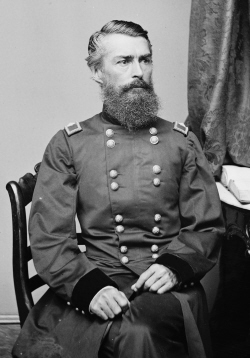
The first intensive use of the dedicated carfloating of freight in the United States seems to have occurred during the Civil War, when freight cars were floated on makeshift barges along the Potomac River, to serve places where existing rail lines could not reach for various reasons. As published in "American Railroad Freight Car", by John H. White, Jr. (1993, Johns Hopkins University Press) credits Brigadier General Herman Haupt for first carfloating on a barge in 1862, during the Civil War. In the October 2000 issue of "Model Railroader" magazine, p. 82-85 there is an illustrated article on the November 1862 construction, under the direction of Brigadier General Herman Haupt, of a carfloat operation for the Union Army at Alexandria, Virginia.
Haupt had been the Chief Engineer of the Pennsylvania Railroad and was in the process of constructing the Hoosac Tunnel when he was "conscripted" to run the U. S. Military Railroad. Two steamtug drawn floats were constructed, each holding 8 cars transversely, and they were served by triple-track aprons at the transfer landings, running from Alexandria, Virginia, down the Potomac River 60 miles to Aquia Landing, about 10 miles northeast of Fredericksburg, Maryland.
In addition, George Abdill on page 48 of his book "Civil War Railroads: A Pictorial Story of the War between the States, 1861-1865 "(1961, Indiana University Press) calls it "pioneer car ferry" which it was not. Instead, it was the pioneer carfloat in the United States.
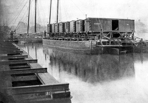
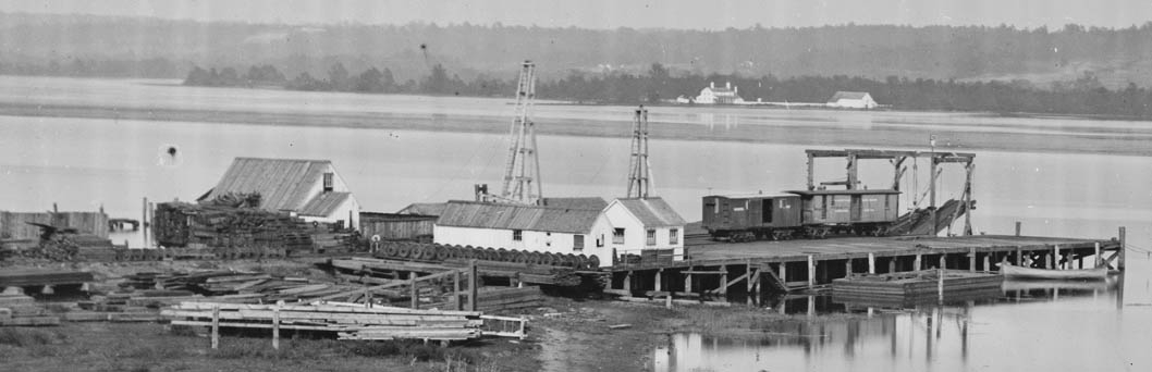
General Haupt supervised the construction of these transfer bridges at both terminals of this proposed water route. General Haupt also designed, requisitioned materials and built the unique railroad float barges. The carfloats consisted of two large-sized Schuylkill type barges moored side by side, across both of which long timbers were placed supporting eight tracks mounted transversely (from port to starboard instead of the modern configuration of bow to stern).
At Alexandria, VA; the loaded freightcars were placed singly aboard each of the eight tracks of the carfloat. The carfloat was then towed sixty miles by steam tug to Aquia Landing, VA. Once at this location, railroad crews unloaded the carfloats by pulling the cars.
We were able to locate three images of the operation in searching the web. All three images are attributed to the National Archives, but were located on a very nice website showcasing Bernard Kempinski's "The American Civil War in Miniature"..
|
|
Haupt, whose first name was sometimes spelled Hermann, was born in
Philadelphia, Pennsylvania, on March 26, 1817, the son of Jacob and Anna
Margaretta Wiall Haupt. Jacob, a merchant, died when Herman was 12 years
old, leaving Anna to support three sons and two daughters. Herman worked
part-time to pay his school tuition, then in 1831 was appointed to the United
States Military Academy at the age of 14 by President Andrew Jackson. He
graduated in 1835 and was commissioned a second lieutenant in the 3rd U.S.
Infantry that July.
He resigned his commission on September 30, 1835, to accept an appointment under Henry R. Campbell as an Assistant Engineer engaged in the surveys of the Allentown road and of the Norristown & Valley Railroad, which opened in 1835 and 15 years later merged into the Chester Valley Railroad. At 19, he was appointed Assistant Engineer in the state service and located the line from Gettysburg to the Potomac across the South Mountain which was then part of the Western Maryland. On August 30, 1838, in Gettysburg, Pennsylvania, he married Ann Cecelia Keller, with whom he would have seven sons and four daughters. In 1839, he designed and patented a novel bridge construction technique known as the Haupt Truss.Two of his Haupt truss bridges still stand in Altoona and Ardmore, Pennsylvania, both from 1854. From 1840 to 1847, Haupt was a professor of mathematics and engineering at Pennsylvania College. He returned to the railroad business in 1847, becoming a construction engineer on the Pennsylvania Railroad, and then general superintendent from 1849 to 1851. He was the chief engineer of the Southern Railroad of Mississippi from 1851 to 1853, and the chief engineer of the Pennsylvania Railroad until 1856; in the latter position he completed the Mountain Division with the Alleghany Tunnel, opening the line through to Pittsburgh. He was the chief engineer on the five-mile Hoosac Tunnel project through the Berkshires in Western Massachusetts from 1856 to 1861. From the spring of 1862, (after commencement of the Civil War), the United States War Department organized a new bureau responsible for constructing and operating the military railroads in the United States. On April 27, Haupt was appointed chief of the bureau by Secretary of War Edwin M. Stanton, with the rank of colonel and as an aide-de-camp to Major General Irvin McDowell, then in command of the defenses of Washington, D.C. Colonel Haupt repaired and fortified war-damaged railroad lines in the vicinity of Washington, arming and training railroad staff and improved telegraph communications along the railroad lines. Among his most challenging assignments was restoring the strategic Richmond, Fredericksburg and Potomac Railroad line, including the Potomac Creek Bridge, after its partial destruction by Confederate forces. With an inexperienced workforce and other serious impediments, Haupt had the line back in use in under two weeks. After his service in the Civil War, Haupt returned to railroad, bridge, pipeline, and tunnel construction. Haupt died of a heart attack at age 88 in Jersey City, New Jersey, stricken while traveling in a Pullman car named "Irma" on a journey from New York to Philadelphia. He is buried in West Laurel Hill Cemetery in Bala Cynwyd, Pennsylvania. |
|
|
|
|
| . | ||
|
|
||
|
The wharfs and transfer bridges at Alexandria, Virginia.
All four photos:
|
||
.
Once the freight cars were unloaded, they were then able to forward those freight cars with their contents, without the need of "breaking bulk" (unloading the freight from the car) along the rebuilt rail line of the Richmond, Fredericksburg and Potomac Railroad to Falmouth, across from Fredericksburg, VA; on the north bank of the Rappahannock River.
According to Haupt this was:
"the first known attempt to transport cars by water with their cargoes unbroken. The Schuylkill barges performed admirably and thus was formed a new era in military railroad transportation. The length of the barges were sufficient for 8 tracks carrying eight cars, and two such floats would carry the sixteen cars which constituted a train."
All of this construction occurred over a period of two weeks. Haupt was ready to support further military operations by November 17th, 1862. As to how the cars were loaded onto the barges, the technology was already in place for carferrying. So the Civil War usage of carfloating maybe was more of an inspiration than an invention, inspiring the New Jersey railroads about how to serve Manhattan without having to unload everything out of the cars onto ferryboats or sail lighters on the Jersey side.
.
.
Carfloating Comes to New York
Harbor
The first mention of carfloating in New York Harbor can be read in the (Trenton) Daily State Gazette, November 13, 1866, p. 3:
"CENTRAL RAILROAD: The Central Railroad Company [of New Jersey] are having a large scow constructed for the purpose of conveying the freighter cars directly from Communipaw to the New York side. It is large enough to hold eight cars which will be run in on rails from the track on this side. It will be in operation next week. The Western mail which has heretofore been carried by the Erie Railway has been transferred to the Central Road."
.
While this article does state fact, it turns out that there were forces behind this operation that were more complex than simply mentioned here. In fact, the Pennsylvania Railroad was the real sponsor, even though at the time its own tracks came nowhere near New York Harbor!
As read in "History of the Pennsylvania Railroad", by J. Elfreth Watkins, 1896; the Empire Transportation Company's line was organized in 1866, it wished to deliver to Manhattan and since the Pennsylvania Railroad did not reach or have a terminal at that location, it contracted with the Central Railroad of New Jersey, which did build the first carfloat for that purpose. Early in 1867, the operation began with the first carfloats carrying those freight cars across the Hudson River. The "car-ferry" route was from Communipaw, NJ Terminal to Pier 14, on Manhattan's west side, which was occupied at the time by the Central Railroad of New Jersey.
By this method, the Empire Transportation Company was able to load & unload its freight cars at Pier 14 in New York City and transport said freight to its destinations without the need to "break bulk". Arrangements were then made by the Union Railroad and Transportation Company with the Camden & Amboy Railroad and the New Jersey Railroad & Transportation Company for hauling these freight cars through Jersey City, instead of unloading the freight in New Jersey, and transporting it via steamboat between South Amboy and Pier 2 in Manhattan, which had been the existing procedure.
Now this explanation clarifies why both the Central Railroad of New Jersey and the Pennsylvania Railroad have taken credit for the first carfloating operation, and why both have been stated in various sources that they served Manhattan's Pier 2. Furthermore, this explanation coincides with the mention in the Trenton Daily State Gazette.
This history of the Pennsylvania Railroad as cited above, had been compiled for several years by people at the railroad; but it was never actually published. It was supposed to have been published in 1896, and apparently was not changed after that date. So unfortunately it is not easy to consult the original text.
At this point we might as well explain the role of those "Lines" (joint lines) that were the means by which freight was expedited between distant terminals in the days before the railroad system itself was fully integrated. A modern day comparison would be the way we send our packages to some foreign destination by using a courier such as UPS or FedEx. Instead of our (the individual) having to deal and coordinate with the airlines and various trucking companies, we contract a firm such as UPS or FedEx which does all this for us as their line of business. Most of the "Lines" were jointly owned by the railroads involved. They were subsequently "branded" with distinctive names for advertising purposes, as the "Empire Line".
.
John Henry Starin's contribution (or lack there
of?)
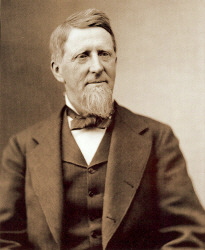
Now, from time to time, the name John Henry Starin seems to be attributed to carfloating. At first it appeared he was significantly involved in the development of carfloating in the New York Harbor area. His obituary as it appeared in the New York Times dated March 23, 1909; reads:
"He originated the idea of transporting freight cars on floats, and was very proud of this achievement..."
This might be a bit of an overstatement
however, as it should be noted from historical references, that car ferry
service preceding the development of carfloats. Car ferries, from my
understanding, appeared to be predominately for the transport of passenger
cars, while carfloats were simple utilitarian affairs for freight
cars.
.
| As principal owner of Starin City
River & Harbor Transportation, many references reflect that he became
especially involved with the freight handling, lighterage and carfloating
operations of the Delaware, Lackawanna & Western Railroad.
He also was significantly involved in the lighterage for the New York Central & Hudson River, Morris & Essex and Central of New Jersey Railroads. By the late 1800's; Starin's marine fleet consisted of over 125 tugboats, lighters, steamers, barges and other assorted pieces of marine equipment. However, from established historical resources show that carfloating existing before then. Did Starin simply bring the idea of carfloating from another port and implement service in New York Harbor? Or did he standardize track and toggle positions between the various railroad's carfloats and float bridges, so that one railroad's carfloat could be moored at any other railroad's float bridge? It appears this credit to Starin for inventing carfloating seems to stem from family biographies, which also attribute Starin for almost everything new in the marine world. So unfortunately at this point it appears that the claim of Starin originating the idea of carfloating seems to embellishment and / or overzealousness of family members. Starin's true contribution, if any; to New York Harbor carfloating seems to have been lost (at least temporarily). |
John Henry Starin |
.
.
Introduction to Transfer
Bridges a/k/a Float Bridges of New York
Harbor
| Overview | Float Bridge Types | Design Requirements | Float Bridge Appliances |
| Carfloat / Float Bridge Interface | Float Bridge / Land Interface | A Popular Misconception | Idler / Reacher Cars |
| Bridging a Carfloat at a Pontoon Type Float Bridge | Bridging a Carfloat at an Overhead Suspended Transfer Bridge | Drilling a Carfloat | |
...
..
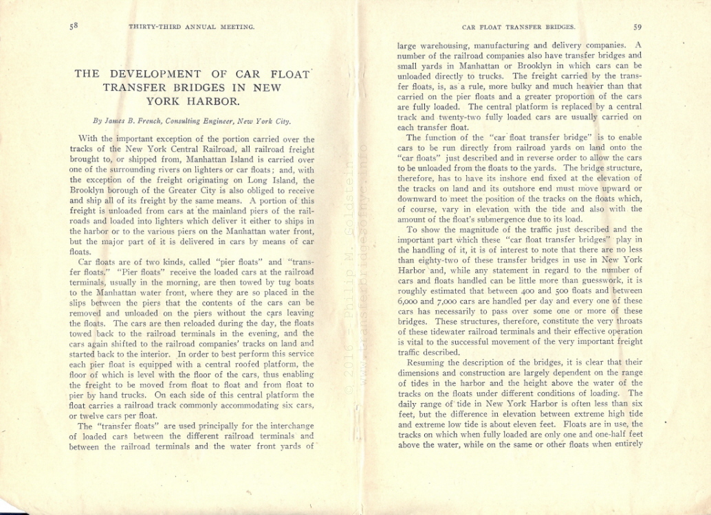
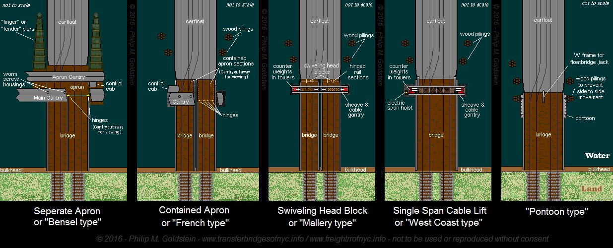
"Transfer bridge" is the general name for the type of bridge that allows running railroad cars directly between land and a boat. This term was used by the engineers who designed them but the term used by railroad workers varied; different regions had different names, as well as distinctive designs. At the Port of New York they were often called "float bridges", and they were here in abundance: through the first half of the 20th Century, there were around 80 or more active bridges. Even during the midst of the Depression, over 5000 cars per day were handled via carfloat in the harbor, according to the National Geographic for November, 1936! The three best known kinds of float bridges at New York (Fig. 1) closely paralleled those at Philadelphia, and were similar to those at Baltimore and Boston. The float bridges of Great Lakes and Western designs were different.
Most descriptions of the designs that have been come across in engineering journals described innovations at Port of New York, as though all the pioneering was done there. That may simply reflect the bias of the journal editors of the time as most were headquartered on the East Coast. On the other hand, the pressure to improve them was greatest in New York, because here they were absolutely vital to the functioning of the terminal.
The Port of New York is geographically an archipelago, with water channels separating densely built up land areas, a situation that forced the railroads to terminate freight for the port over water instead of laying rails on a land, creating a kind of "water belt line" system. Without this flexible system, New York would not have been the leading port in the United States (handling 40% of U.S. foreign trade during most of the railroad era). Moving railroad cars around on the water was one of the primary marine operations here.
.
.
| RETURN TO CHAPTER INDEX | RETURN TO MAIN INDEX |
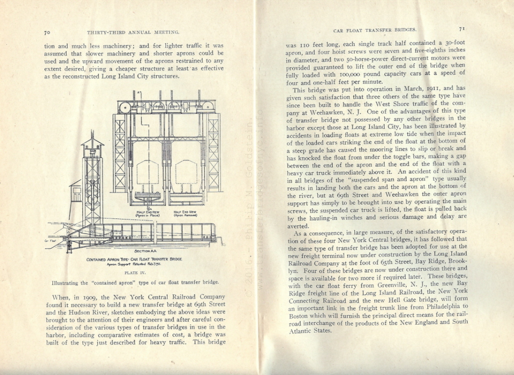
A float bridge is basically a bridge span anchored and hinged to land on one end, and hung over or supported by the water on the other. The end over the water could be supported by an overhead gantry carrying cables to counterweights to support the dead load weight of the float bridge, as in the case of the Separate Apron of "Bensel" type, Contained Apron or "French" type, Swivelling Head Block or "Mallery" type or the Cable Lifted Single Span "West Coast" type.
The type supported by a pontoon in the water which kept it afloat by buoyancy was simply known as (what else?) Pontoon type.
Both the Separate, Contained Apron and Cable Lifted Single Span designs feature electrically controlled motors for lifting and lowering the bridge spans, as well as for the contained apron design and both the bridge and apron spans for the separate apron type.
The "Mallery" and the early "West Coast" types were manually raised and lowered via counterweights and chain fall system.
The pontoon could have a lightweight overhead gallows with a block & tackle / chain fall or a manually operated hydraulic piston for raising.
.
.
| RETURN TO CHAPTER INDEX | RETURN TO MAIN INDEX |
The carfloat itself is not a complicated craft, since it is towed around by tugboats and thus needed no machinery. It is simply a strongly built rectangular barge fitted with tracks. Originally it was constructed of wood with a capacity of 8 cars on two tracks; in later years it would be made of steel, and some of them reached lengths of 320 to 360 feet with a capacity of about 22 cars on three tracks. By about 1900 they were standardized to the point that any float bridge could handle any railroad's float, at least in New York.
Providing a continuous line of track between land and carfloat was a bigger engineering challenge. A "transfer bridge" or "float bridge" not only has to have the strength of a regular bridge but also has to meet requirements that other kinds of bridges do not face.
One of these is vertical motion at one end. While the inshore end of the bridge must be at a fixed height, the water or outshore end must be able to rise and fall. The typical daily tidal range is 5 to 6 feet, with an extreme range of about 11 feet (Engineering News, 1911), though in the most extreme conditions (i.e.: storm surges) operations are simply suspended. In addition, the load on the carfloat determines the free board. Some empty floats might have rails as much as 8 feet above the water, while the heavily loaded one might have rails only 1.5 feet above. The overall operating range at New York was generally taken to be 17.5 feet. (French, 1917). Note also that for a bridge a length of 100 feet (typical at this port), this range would give a maximum rate of 8.5% up and 8.5% down from a midpoint giving the switch engine some real work to do.
A second design challenge is torsional stress. During the loading and unloading, a carfloat lists to one side or the other, requiring twisting motions unknown in normal bridge service:
Pontoon / Howe Truss Float Bridge at Erie Railroad
West 28th Street Freight Station, Manhattan, NY - 1910
Pier 67 to left - looking west.
New York City Department of Docks photo
T. Flagg archives
added 03 January 2012
.
This motion must be taken up somewhere in the structure since at the shore end there can be no twisting. This twisting also puts great difficulties in the way of the float bridge designer who tries to suspend the outer end of the bridge from any rigid support such as a lifting screw.
.
.
| RETURN TO CHAPTER INDEX | RETURN TO MAIN INDEX |
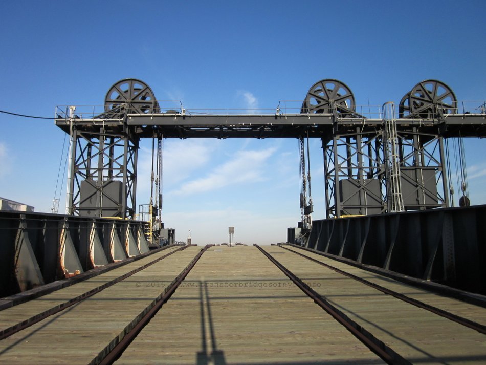
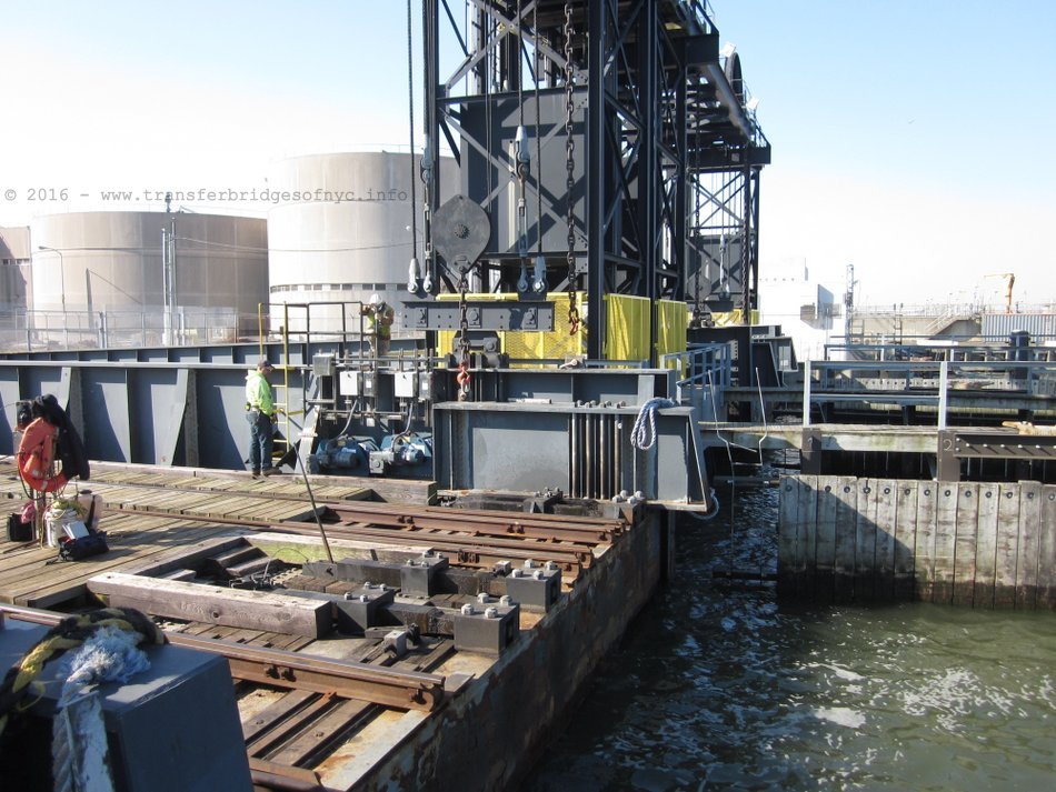
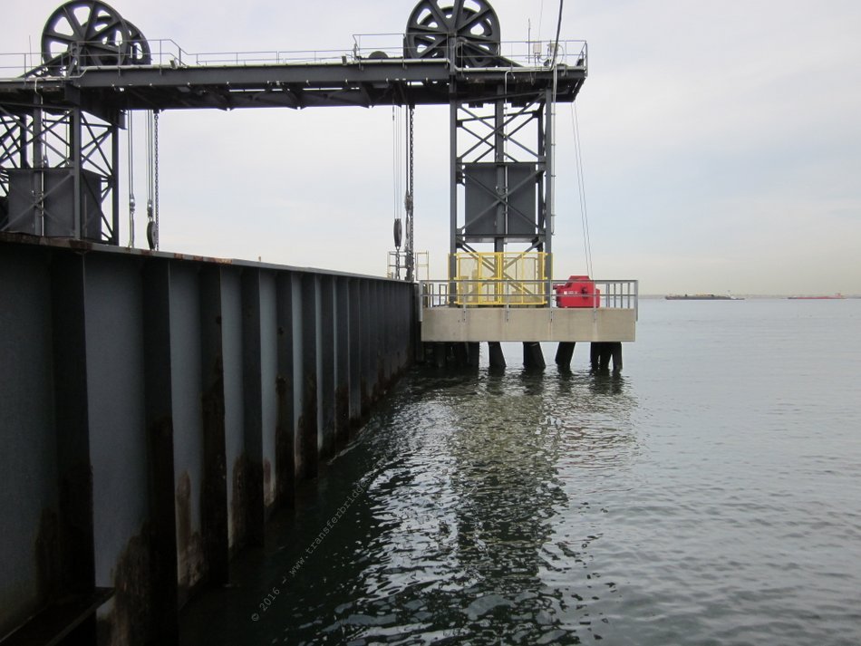
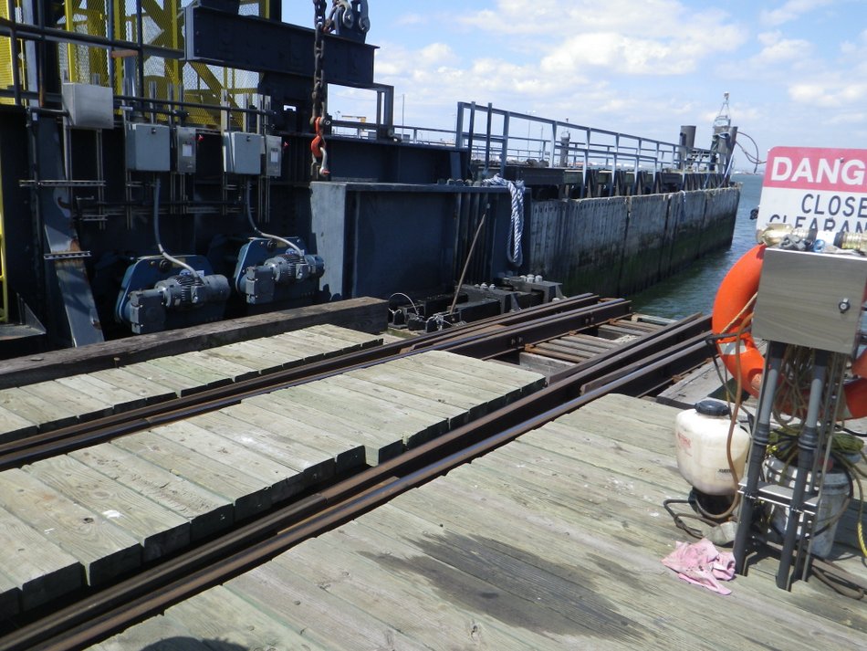
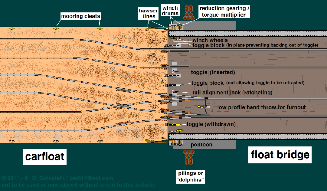
The illustration below shows the appliances found on almost all float bridges used throughout New York Harbor. Clicking on the illustration below will bring you to close up of the appliances. Use the back arrow on your web browser to return you here. For the most part, other than the obvious difference being the pontoon versus the overhead counterweighted suspension types ; the only differences between the manual pontoon type float bridges and the electrically operated overhead suspended type transfer bridges were the main winches were powered by electric as well as the lack of float bridge jack (of which wasn't needed as the span & apron height were electrically controlled) on the overhead suspended types of transfer bridges.
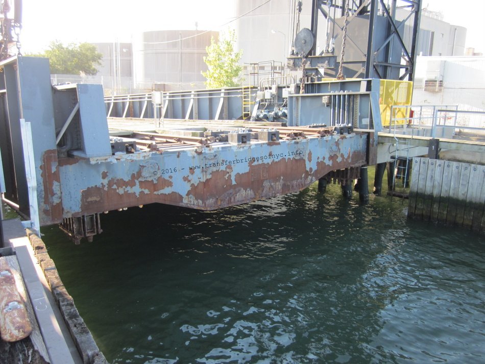
In the image below, a pontoon type is shown. Please take note that the only appliance not shown is the float bridge jack and a-frame. The reason for this is that this component has not been used in day to day float bridge operations for the last 20 years. Matter of fact, by referencing current images of New York New Jersey Rail float bridge operations in Brooklyn, the float bridge jack is not even mounted on the Bush Terminal float bridge in service.
This appliance, if it were to have been included in the diagram below, would have been located between the center two toggles with the hydraulic piston overhanging from the edge of the float bridge.
DIAGRAM NOT TO SCALE
 |
.
.
.
| RETURN TO CHAPTER INDEX | RETURN TO MAIN INDEX |
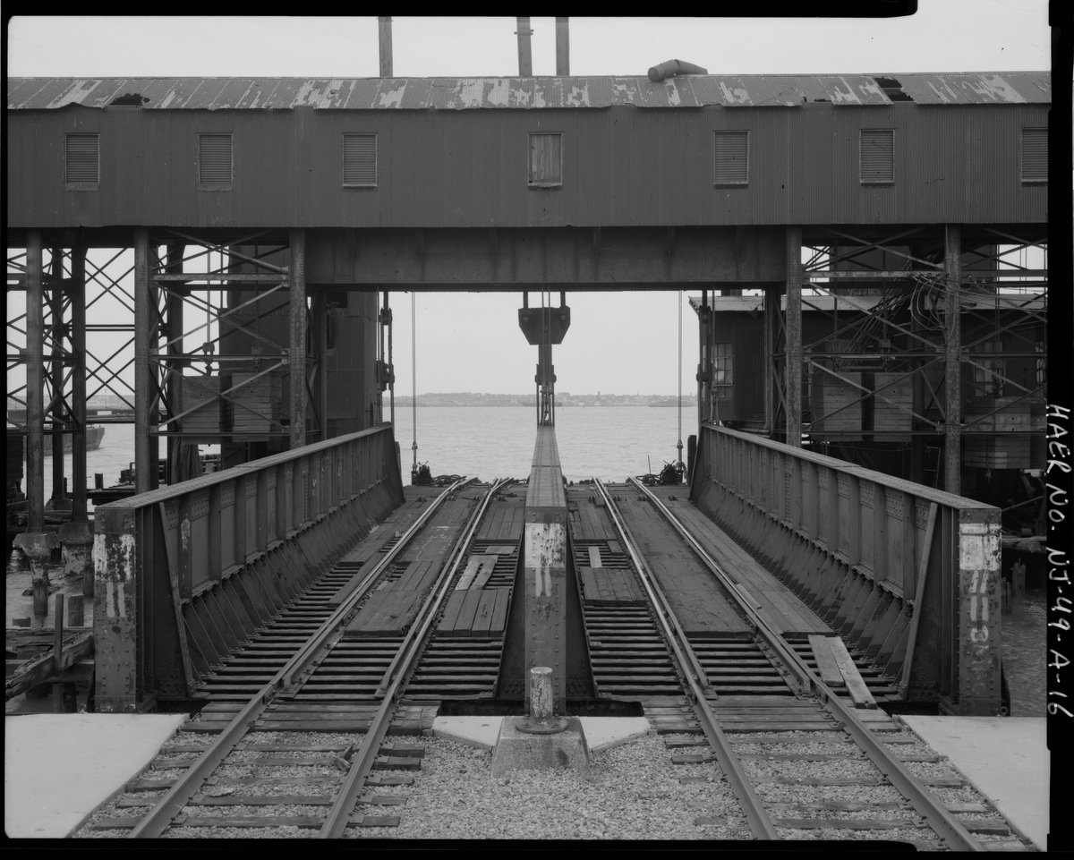
Float Bridge
and Carfloat Interface
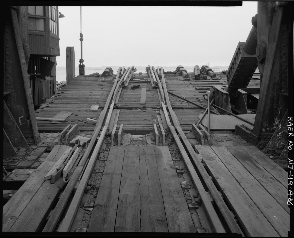
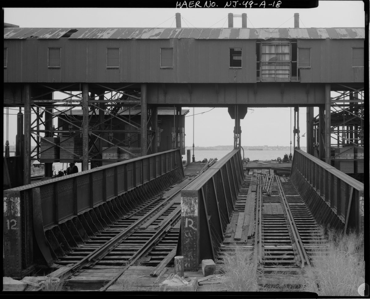
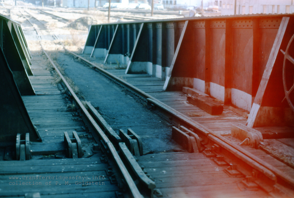
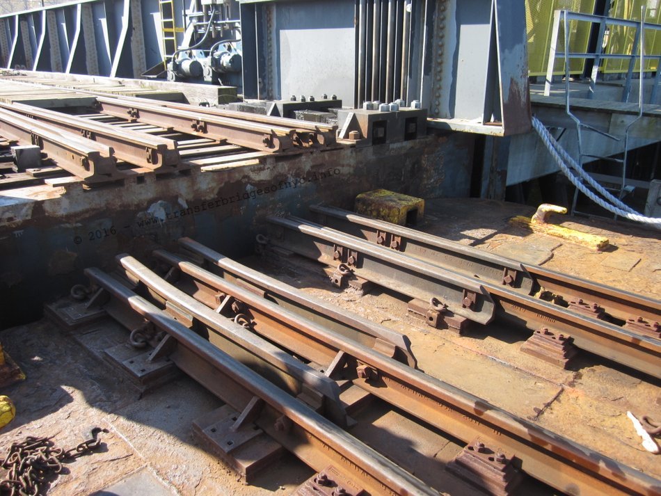
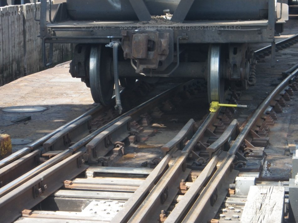
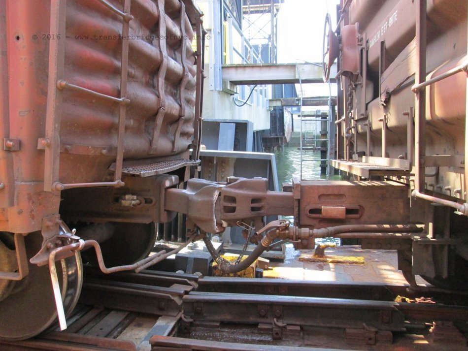
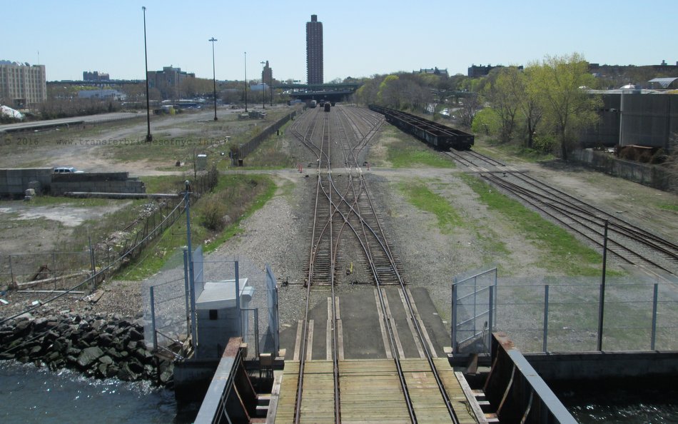
On all bridges at the Port of New York, the left track (as one looks from land to water) splits into two tracks just before the edge of the bridge. The bridge contains the "point" portion of the railroad track switch; while the "frog" portion is located on the deck of the carfloat, on those interchange type carfloats containing three tracks. The switch begins 23 feet 9 inches back from the outshore end of the bridge, and the diversion tracks are separated 18in. at the end of the outshore end of the float bridge giving a frog number of approximately 16 (Engineering News, 1911, 773).
Carfloats containing only two tracks (such as station or platform carfloats) simply continue the left track only. Plans and photos from the 1880's and early 1890' do not show this frog; the arrangement apparently came into use at New York about the turn of the century. John Droege (1912, 225), in his description of transfer bridges said it was standard. There is some suggestion that the Pennsylvania Railroad started this arrangement and forced its acceptance as a standard (duBosque, 1915).
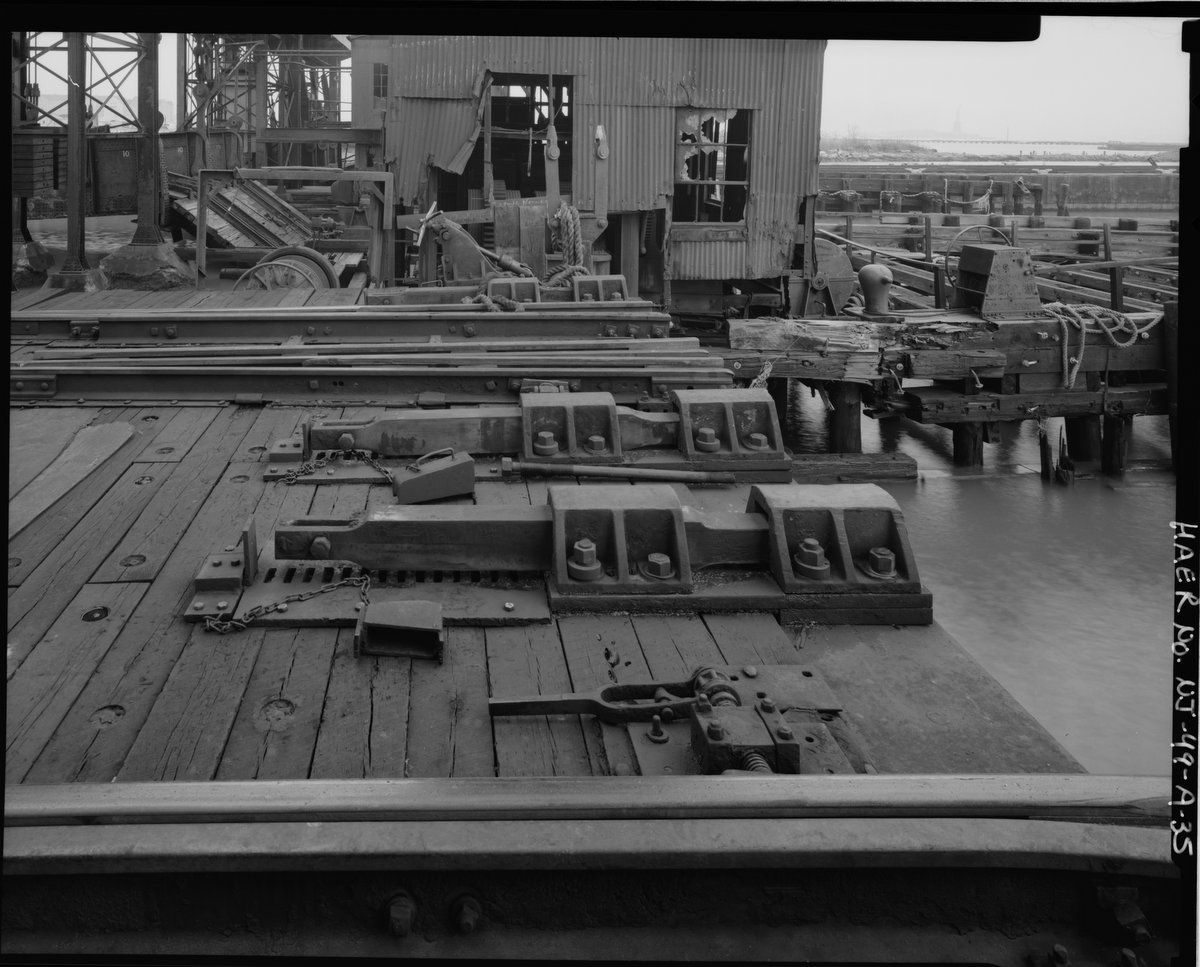
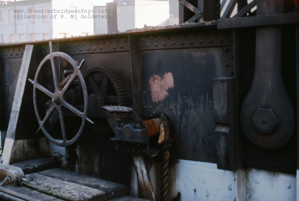
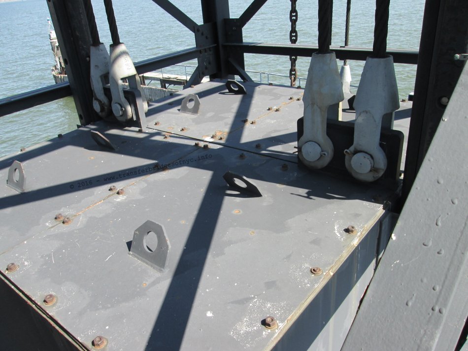
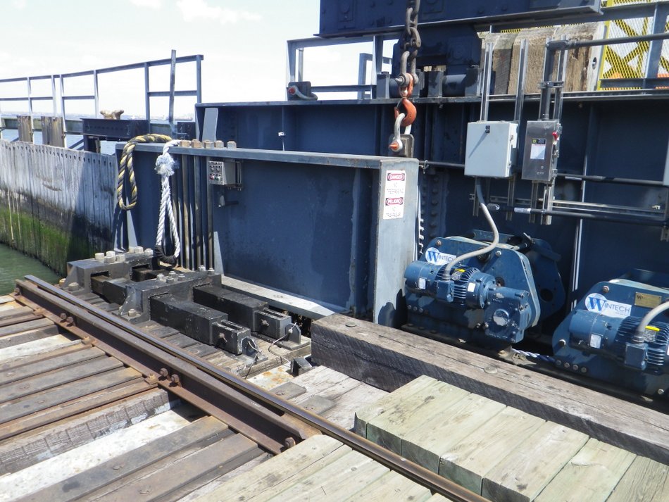
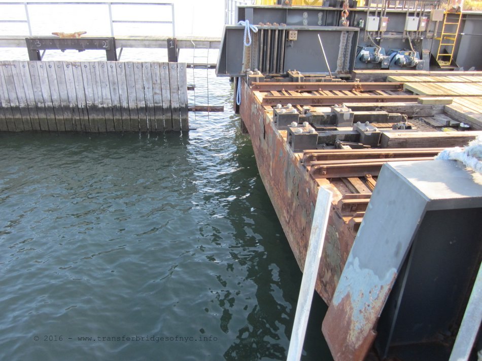
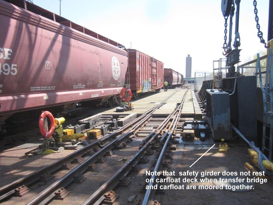
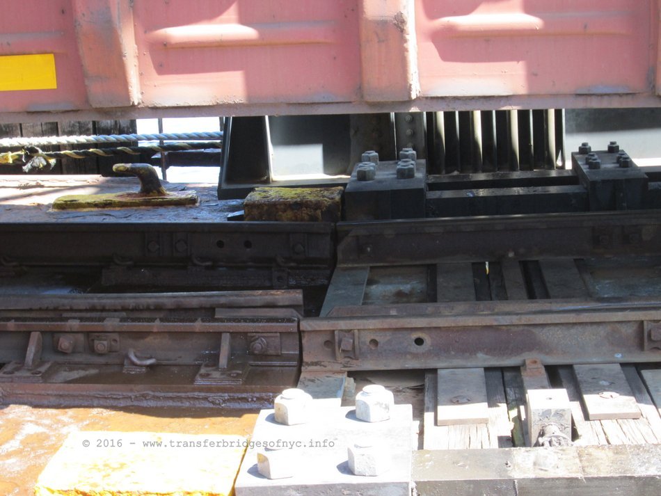
Carfloats are held in proper alignment with the float bridge in two ways: they are held snugly to the bridge with heavy rope or lines ("hawsers") and with toggle bars.
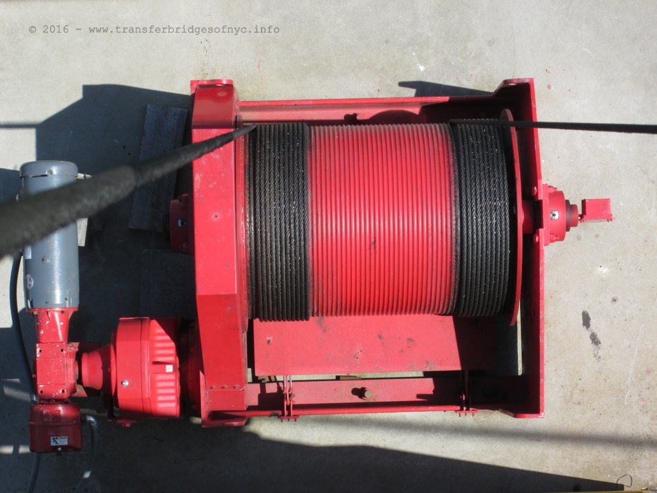
To keep the carfloat from moving away from the face of the float bridge, heavy cables or ropes (hawser lines) are used. These are winched tight with the winch wheels seen on the float bridge. It is all too often stated that these wheels on the float bridge are to control pumps, to flood or empty a pontoon but this is simply incorrect. The lines are denoted in the diagram above as #15. At the ends of these lines were steel hoops which placed around their cleats on the carfloat. Today, the line itself is braided into a loop.
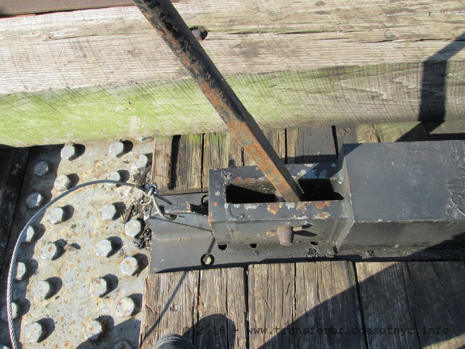
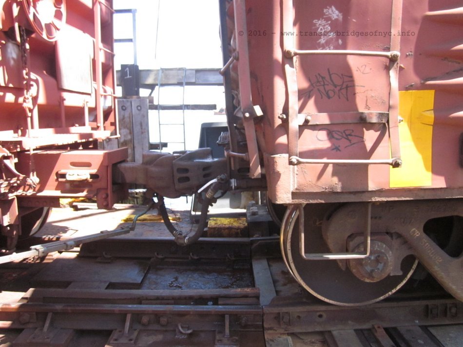
Each transfer bridge has either four or six toggle bars contained in sockets. When the bridge and carfloat are correctly aligned horizontally with one another, the "toggle bars" (#16 & 17 in diagram above) are slid into corresponding toggle receptacles (#18) mounted on the end of the carfloat. The toggle bars are of alloy steel and were originally 5 inches square in cross section and 7 feet long (Snow, 1901), but a later revision has these toggles manufactured with a 7" cross section. They were slightly tapered at the point to facilitate ease of sliding into the receptacle on the carfloat. These are most often moved with the aid of a long pry bar. (Once all the toggles are extended into the receptacles on the carfloat, the carfloat can be kept in lateral and vertical alignment to the float bridge.
Under the toggle bar as part of the fixture mounted into the deck of the float bridge are rectangular notches. These can be seen in the patent file by James B. French (but this design existed before this). A steel block with a grab handle on top and studs on bottom was then placed behind the toggle bar, thereby locking the toggle bar it into position, after it was extended into the carfloat toggle receptacle. This prevented the accidental backing out of the toggle bar. The studs on the bottom of the block fit neatly into those notches in the toggle bar fixture. In addition, final adjustments of the lateral position of the rails at the outer end of the bridge, is accomplished with a ratcheting handle attached to a screw arrangement (Fig. 5, 8A, 8B). This device allows adjustment for small differences in rail positions on different carfloats.
After this was accomplished, the lines were given a final tightening via the winch wheels.
..
.
.
| RETURN TO CHAPTER INDEX | RETURN TO MAIN INDEX |
Float Bridge &
Land Interface or "Bulkhead
Anchors"
.
|
|
To keep all types of float bridge spans secure to the bulkhead,
they had to be secured in a way that prevented them from floating away or
pulling away from the bulkhead, but still allowed them to pivot vertically.
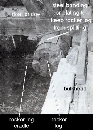
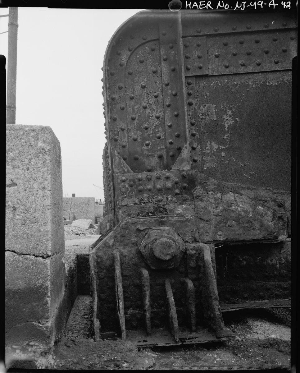
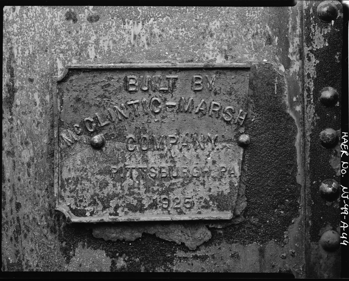
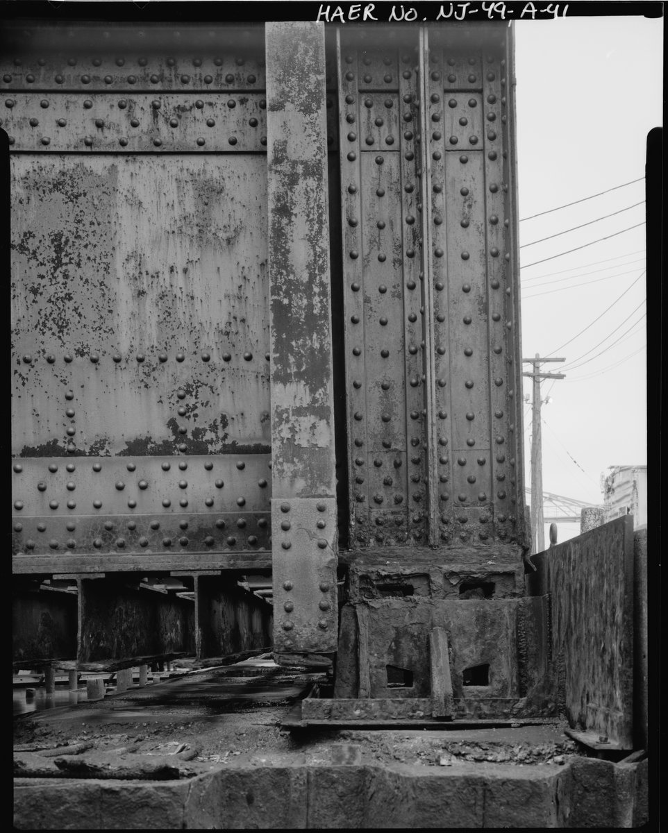
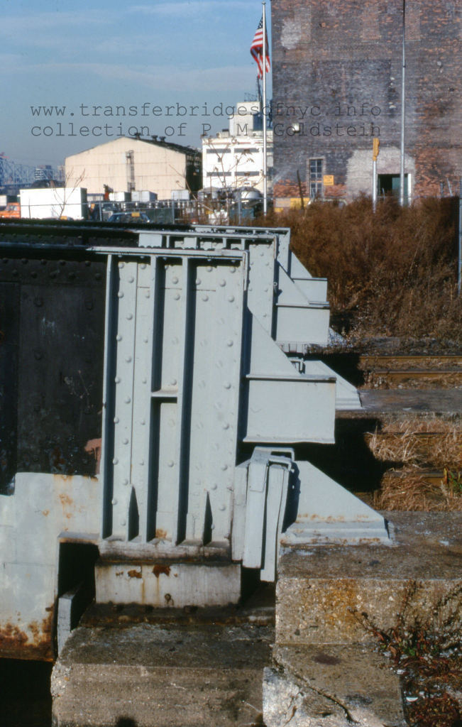
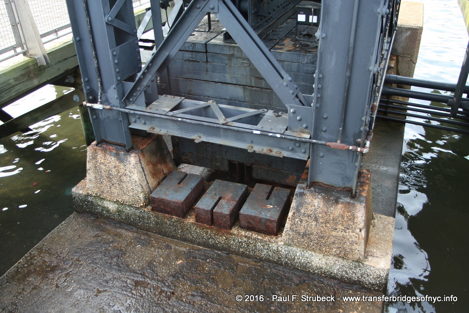
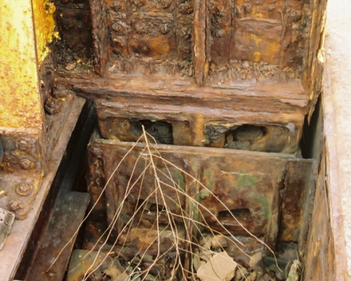
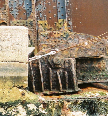
Wood Howe Truss In regard to the earliest designs of wood Howe truss float bridges, the inshore end of the float bridge had a round log mounted transversely to the bottom of the deck. Wrapping around the circumference of this log and the exposed ends was steel banding or sheet metal to prevent the splitting and separating of the log. On the bulkhead, there was wood blocking with a concave portion carved out to receive the rocker log. This was in effect a cradle. The rocker log was set into the cradle and pivoting was not hindered. As far as can be told, the rocker log type anchor was only used on Howe truss float bridges. Steel Pony Truss or Through Plate Girder With steel bridges there were two designs of float bridge anchor. With advent of steel casting, a newer apparatus was designed. Working on a similar principle to the rocker log, the pivot wheel & box anchor was created. The semi-circular pivot wheel was set into a cast box. The other method was a pin and plate. Both of these can be seen below. Ironically, both of these anchor methods were used at the same facility at Greenville, NJ. The pivot wheel & box design is in place on Bridge #11 (the only transfer bridge at this location which is in operation) and the pin and plate method is on Bridge #10. These differences are attributed to the bridge designer who is contracted to build the bridges: Bridge #10 (out of service) and was built by McClintic - Marsh was headquartered in Pittsburgh, PA. Transfer bridge #11 was built by American Bridge Company of Coraopolis, PA. |
 |
 |
|
Pivot Rocker & Box Anchor
|
Pin & Plate Anchor |
both photos by P. M. Goldstein - May 2009
Greenville, NJ
added 04 January 2012
.
..
.
.
| RETURN TO CHAPTER INDEX | RETURN TO MAIN INDEX |
The following statement is repetitiously heard in both prototype railfan and scale modelling circles:
"The locomotive is never placed on the float bridge or carfloat".
.
This statement, quite simply; is incorrect.
Furthermore, it is doubted that this practice in general was
ever "prohibited" by an actual rule as dictated by a railroad. Research
and reference to
various Employee Time Tables, locomotive operating manuals, general
operations
manuals, Rule Books, and/or Marine Rule Books for those Class 1
Railroads having carfloat
operations in New York Harbor, have failed to show any generalized
prohibition of locomotives on the float bridge or carfloat.
It is completely understood that certain locomotive classes
exceeding dimensions due to either wheelbase length or overall weight would have been excluded from using the transfer
bridge, just as would locomotives that exceeded an axle loading would be
restricted in using some light branch lines or due to bridge span capacity.
But to have "any" locomotive banned from setting a wheel on a transfer bridge or carfloat? Not so. Think about it, why would a locomotive of average weight be precluded from use of transfer bridge when the standard 40' boxcar of the era weighed 30,000 pounds and had a weight capacity of 100,000 pounds. Two fully laden boxcars equalled 260,000 pounds and weighed more than the average 0-6-0 or 0-8-0 switching locomotive; to say nothing of a oversize dimensional loads seen being transported on carfloats. In later era of operations; 60' boxcars, fully loaded weighed 286,000 pounds. The average road switching locomotive, i.e.; an ALCo RS3 weighed 247,000 pounds; or 39,000 pounds LESS than the freight cars!
Naturally, if anyone can find any rule listed in any New York Area railroads' rule book pertaining to float bridge operations, where it is specifically stated (in any wording format) where a locomotive was prohibited upon the float bridge; you are more than welcome to present it and invited to share it here.
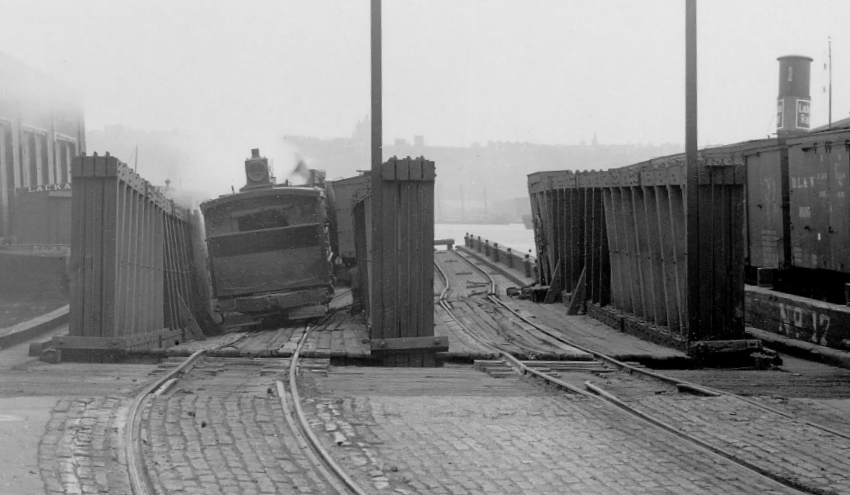
If mere words are not enough, if one refers to the 1910 photo in the "Design Requirements" chapter above, you will clearly see a steam locomotive on the float bridge at Erie West 28th Street. In fact, the Brooklyn Eastern District Terminal would as part of normal operations, repetitively send a locomotive (steam or diesel) on the carfloat along with the freight cars, to its Pidgeon Street Yard or to the Brooklyn Navy Yard.
In the photo below, you will see numerous hoppers full of coal, weighting in at 80-100 tons per car. The lightest thing on the carfloat (besides the empty flat car) was the locomotive (64 tons)!
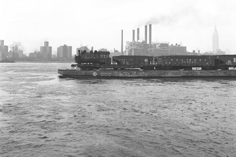
East River - 1954
#15 aboard Carfloat #22 and enroute to Brooklyn Navy Yard (note loaded coal
hoppers for BNY powerplant).
S. Meyers photo
D. Keller archives
P. M. Goldstein collection
added 24 January 2012
.
Furthermore, any number of images within Tom Flagg's books: "New York Harbor Railroad's in Color", clearly show locomotives of various railroads, weights and sizes on both overhead suspension and pontoon type float bridges and / or carfloats:
Volume 1: p. 25 (CNJ); p. 44 (HT); p. 52 (ERR); p. 55 (ERR); p. 63 (LIRR); p. 107 (BEDT); p. 126 (HS)
Volume 2: p. 19 (BT); p. 42 (EL)
If one further attempts to argue that the locomotives in those images were "lighter switching locomotives", then I refer you to this image: even large heavy switcher type locomotives are seen on the transfer bridges at Greenville, NJ:
Railroad Magazine, September 1945
"Boxcar Navy" by William L. Rohde
appears to be a 'H class' "Consolidation" 2-8-0 which weighed between 220,000
and 247,500 lbs.
added 24 January 2012
.
.
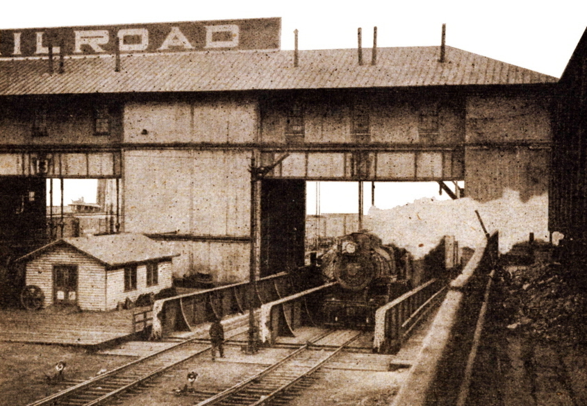
And here we have a great photograph of a Baldwin built H-10 class Consolidation on the Long Island Rail Roads' Long Island city Transfer Bridge #5, taken in 1945. Built as PRR #7205 in November 1913, it went to the PRR in July 1928, and weight between 220,000 and 247,500 pounds. This image is significant as the date of 1945; illustrates a steam locomotive operating in Queens (within the city of New York), and after 1931, which is supposedly after the Kaufman Law in full effect (of which via research we now know it was overturned in 1926). This can be read on another of my pages of this website: Steam Locomotive Legislation, Regulations and Restrictions in and around the City of New York: 1834 - 1930
![]()
Queens Public Library Digital Collection
This next image was located on the internet, courtesy of the Baltimore Sun digital archives. It is of Santa Fe (AT&SF) #3829 "Texas" 2-10-4 locomotive on a carfloat, and an older wood hull carfloat at that! The locomotive was constructed in 1919 by Baldwin Locomotive Works, so from the new appearance of the locomotive, that image could be dated accordingly.
The total weight for the locomotive and tender was 679,000 pounds. This locomotive was rolled onto the carfloat, and not hoisted or rigged aboard. This means both the carfloat and the float bridge were obviously able to support its weight.
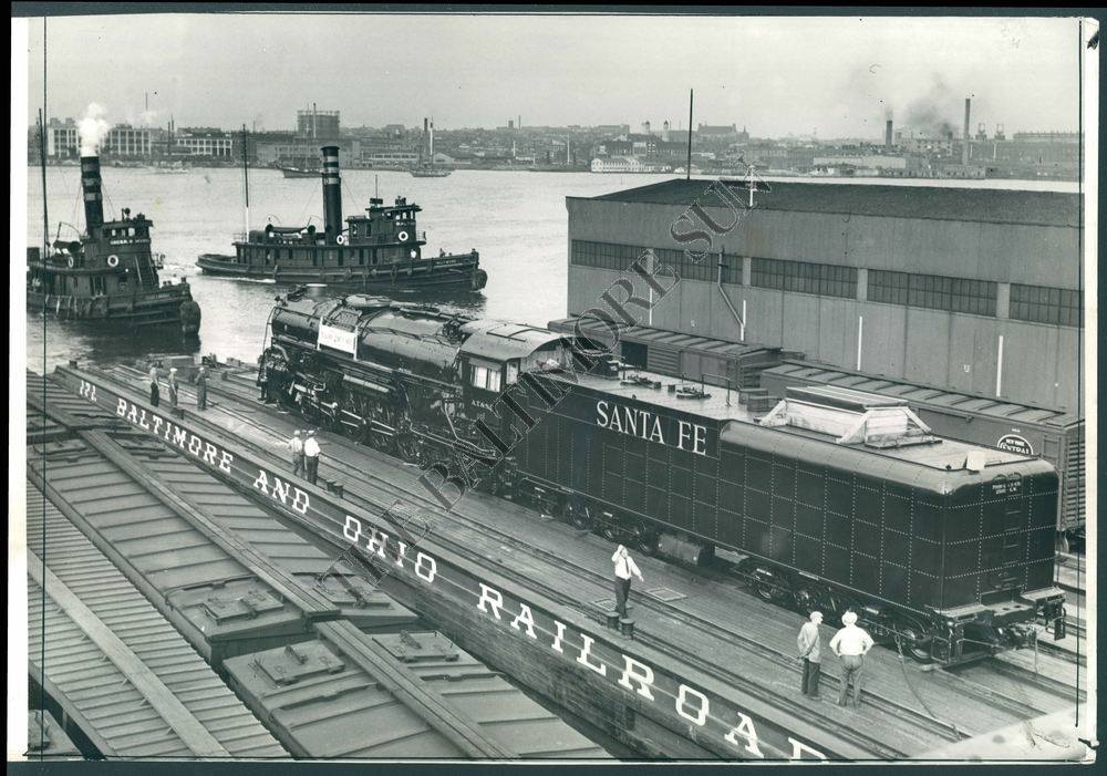
courtesy Baltimore Sun digital archives
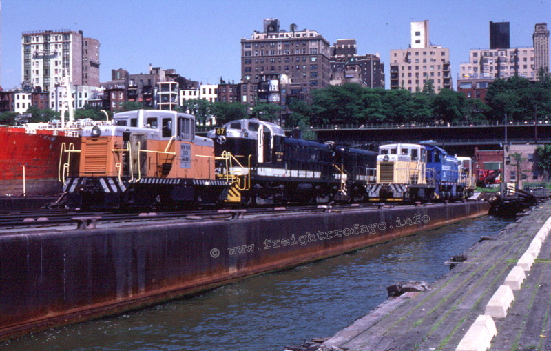
| two ALCo RS3's | NYD #56 & #57 | 247,100 pounds each | 494,200 lbs |
| four GE 44 tonners | NYD #51, #52, #54 and #55 | 88,000 pounds each | 352,000 lbs |
| three ALCo S1 | BEDT #26 and #23 (out of view on the other side of the RS3's) and #24 | 199,000 pounds each | 597,000 lbs |
.
.
And, if this photographic evidence is not enough, or the obstinate tries to take the position that those images above were taken in the "older era" of operations, then I ask you then simply to review the following image and / or watch the video at the 7m 45s mark that I took in May 2011 of NYNJ Rail - carfloat mooring & car unloading (first carfloat): Bush Terminal 50th Street "Bush 2" Float Bridge, Brooklyn, NY. In this video, you will witness a 248,000 pound SW1500 diesel locomotive both sit upon and cross the float bridge to board the carfloat to couple up to the freight cars. This took place in everyday regular operations of New York New Jersey Rail, prior to relocating to the 65th Street Yard.
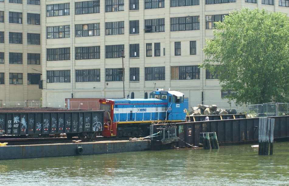
New York New Jersey Rail #1133 on Bush 2 float bridge
& Carfloat 16- May 31, 2011
Note the float bridge pontoon is completely submerged on this side.
P. M. Goldstein photo
.
So, um... yeah..
This misconception of "locomotives being too heavy for a float bridge or carfloat" is one of; if not the most prevalent misstatements regarding float bridge and / or carfloat operations.
.
.
.
| RETURN TO CHAPTER INDEX | RETURN TO MAIN INDEX |
Some railroads, especially the Long Island Rail Road; preferred to use "idler" or "reacher" cars. According to Droege, (1912, 225) the main reason for using idler car when moving freight cars on and off the carfloat, was that often the vertical alignment of the carfloat and float bridge was imperfect, especially when the toggle bars were worn, and that it would be bad to run a heavy locomotive over such a vertical misalignment. The use of an idler / reacher car operation however, was up to each particular railroad and location.
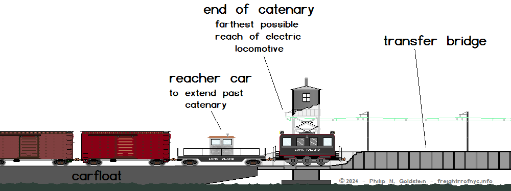
Another factor that required the use of a reacher car can be observed at the LIRR / NYNH&H Bay Ridge Yard (or any other overhead catenary power supply operations such as the Delaware, Lackawanna & Western's Wallabout Terminal or the Oak Point Yard of the New York, New Haven & Hartford RR.
Each of these yards had the uniqueness of having an electric catenary for locomotive operation. As this catenary could only extend to the outshore end of the transfer bridge, and as such; locomotives could not progress past the point and therefore could not enter upon the carfloat to couple onto the freight cars. Therefore, an idler car or two took up the remaining space between the locomotive and freight cars:
Even after the operations of the Bay Ridge Yard switched to diesel electric power exclusively in the 1958, the idler cars stayed in use and presumably as a result of that already established policy. Idler car use did not live for much longer after this with the Bay Ridge Yard closing in its entirety in 1968.
In most cases, idler / reacher cars were made up from gondolas converted for use as a reacher car (ballasted with weight, openings cut out of the sides at both ends for easy entrance / egress, benches for crew and safety handrails) as in the case of Bush Terminal reacher cars #100 or 101; or as in the case of the reacher cars used by the Long Island Rail Road which were quite fancy: a shanty and windows (and a stove!) was mounted to the deck of a flat car, and a waist height railing placed around the perimeter of the flatcar for crew safety.
But in fact, any empty freight car could be pressed into expedient service as an idler / reacher car.
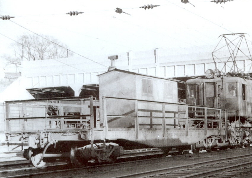
Long Island Rail Road Float Reacher Car - ca. 1958
Note, electric catenary locomotive. Bay Ridge, Brooklyn, NY
F. G. Zahn photo
added 24 January 2012
.
Other railroads did not employ reacher cars: Brooklyn Eastern District Terminal, whether it be the small tank locomotives (64 tons) or diesel locomotives (99 tons); or the New York Dock Railroads' light diesel locomotives (50 tons) at Fulton, Atlantic & Baltic Terminals; which frequently drilled the carfloats without reacher cars, and thus the locomotives had to go onto the float bridge and likewise, the carfloats.
In regard to the modern era of operations, and specifically in regard to the only surviving rail-marine / carfloating operation in New York Harbor: New York New Jersey Rail until late 2016; drilled their carfloats without the use of a reacher car.
As of that date however, it appears two Norfolk Southern gondolas (NS 617759 and NS 617591 respectively) are partially loaded with ground up asphalt pavement and sectional concrete retaining wall blocks a/k/a "mafia blocks " and are being used in regular drilling operatings as idler cars. Then sometimes the sit in the yard unused for months at a time and are not used.
.
.
.
| RETURN TO CHAPTER INDEX | RETURN TO MAIN INDEX |
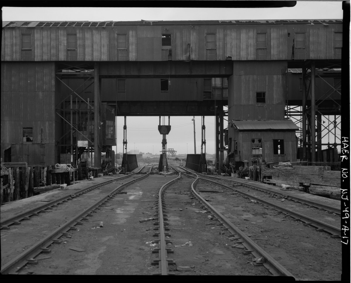
Bridging a Carfloat at a
Pontoon Type Float Bridge
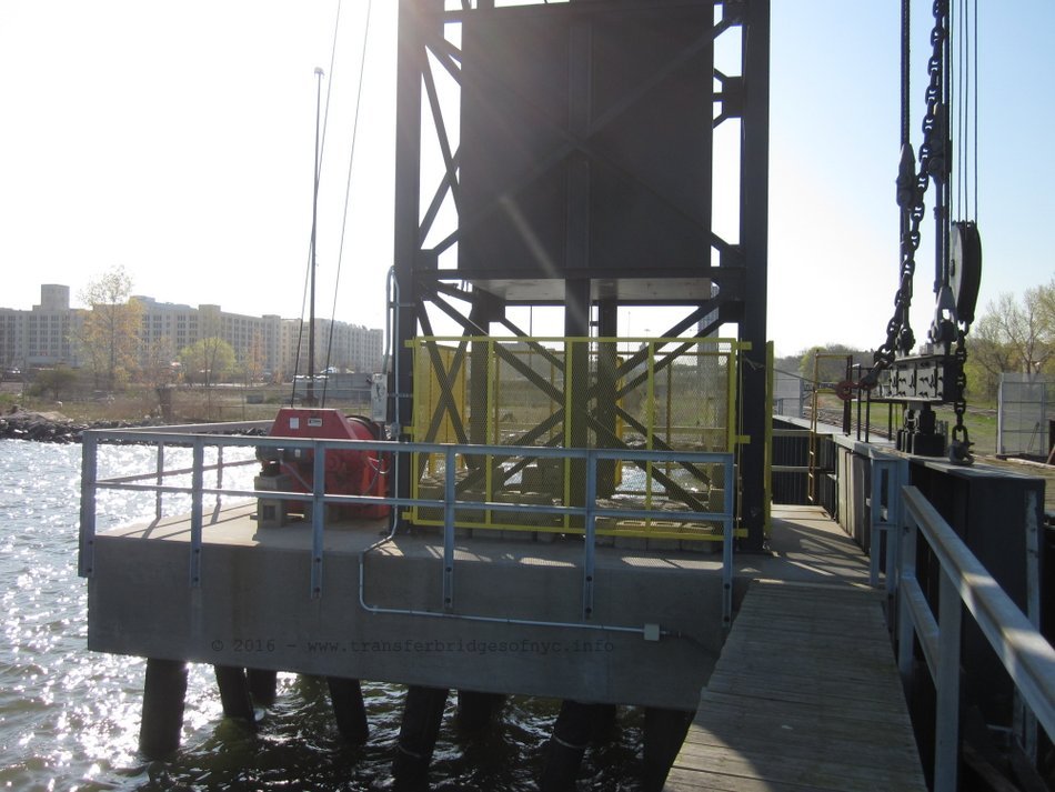
The skill of the bridgemen makes "bridging a float [carfloat]" as it is actually called in day to day operations, look simpler than it actually is. Signals directed an incoming tugboat to a particular float bridge. These signals could be transmitted via steam whistles, electric horns, flags or lanterns in the early days and two way radio after World War II.
The tugboat pushes a carfloat into place and lines are attached to cleats or bits on each side of the carfloat near the shore and. These lines are then all winched in and tightened with hand wheels or electrically operated power winches to draw the carfloat in flush against the bridge.
The end of the bridge is then adjusted to the height of the carfloat as explained above, and the toggle bars are slid into their sockets on the carfloat. A final tightening of the lines can then be done.
..This chapter, once the reader has familiarized themselves with the components of a float bridge; is to give the reader an understanding of the procedures involved in mooring and pinning a carfloat to a float bridge. This is the procedure for normal day-to-day operations. Rarely, this procedure would be modified to accommodate unique occasions, such as special loads, locomotive moves, etc.
To moor carfloats at pontoon type float bridges;
the following procedure applies:
Tugboat approaches float bridge with carfloat,
and holds it in position for mooring;
(In the earlier era of operations, while the following is taking
place, freight clerks would begin inspection of the freight cars and their
seals at this point too);
Four hawser
lines* attached
to front mooring cleats (two on each side) of carfloat and are tightened
up via winch wheels to bring carfloat into initial
alignment. The winch wheels turn the winch drum (which
holds the hawser line) via a gear reduction / torque multiplier system;
Locomotive slowly proceeds onto right track (facing water) of float bridge to weigh it down into the water; and to match height of float bridge with deck of carfloat;
The right toggle bars are slid into carfloat toggle receptacle and fastened with the toggle bar block;
Hawser lines would be tightened again via winch wheels, and mooring lines from carfloat side cleats are attached to finger pier (if applicable);
Locomotive reverses and backs off float bridge,
switches to left track, and proceeds forward on float bridge left track until
left side toggle bars
are aligned with carfloat toggle receptacles;
The left toggle bars are slid into carfloat toggle receptacles and are fastened with the block;
Hawser lines are tightened again;
Hand jacks on the rails on the float bridge would be turned to adjust the horizontal alignment of the rails on the float bridge to match with rails on carfloat if need be;
Chains and / or chocks are detached from the freight cars, and the brakes are then are released. (Hand brakes spun off in early days at BEDT air brakes were not used.)
Locomotive (with or without idler cars) now "drills"
the float (unloads cars from carfloat). For the procedure on this operation,
please proceed to the next step below:
* Certain locations only had two hawser lines
and two winch wheels (one each side of the float bridge). It is believed
that the four line method was used where there were no fender or finger piers
to help secure the carfloat against lateral motion.
..
.
.
| RETURN TO CHAPTER INDEX | RETURN TO MAIN INDEX |
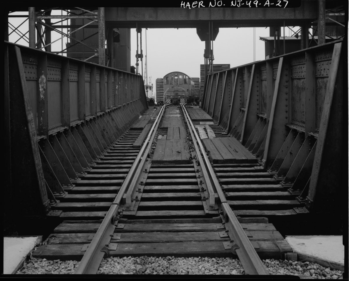
Bridging a Carfloat
at a Overhead Suspended Transfer Bridge
Carfloat mooring and pinning procedures
were a little different at overhead suspended electrically operated type
float bridges (as opposed to that of pontoon bridges) as these transfer bridges
have electric motor for raising & lowered the bridge span and electric
winches for drawing in the carfloat tight against the float
bridge:
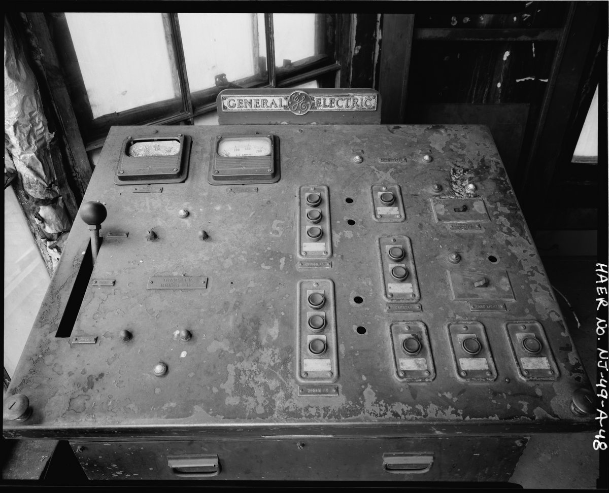
Tugboat brings carfloat in, and the float bridge
and or apron is raised or lowered by the bridgeman in the control cabin to
bring it into correct height alignment with
carfloat.
Hawser lines from power winch attached to front mooring cleats on each side of carfloat.
Carfloat would be drawn in tight to float bridge.
All toggles (pins) would be pried (slid) into carfloat receptacles (toggle boxes) and chocked in place with "toggle block".
Secondary hawser lines from manually powered winch wheels added and tightened.
Hawser lines from carfloat side cleats attached to "finger piers" on both sides of carfloats.
Ratcheting jacks on the rails on the float bridge would be turned to adjust the horizontal alignment of the rails on the float bridge to match with rails on carfloat, if needed;
Locomotive (with
or without idler cars) now "drills" the float (unloads cars from carfloat).
For the procedure on this operation, please proceed to the next chapter below:
.
.
| RETURN TO CHAPTER INDEX | RETURN TO MAIN INDEX |
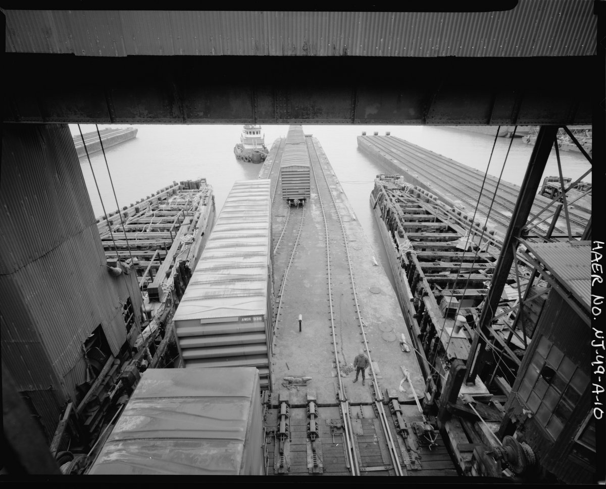
Drilling (unloading / loading)
a Carfloat
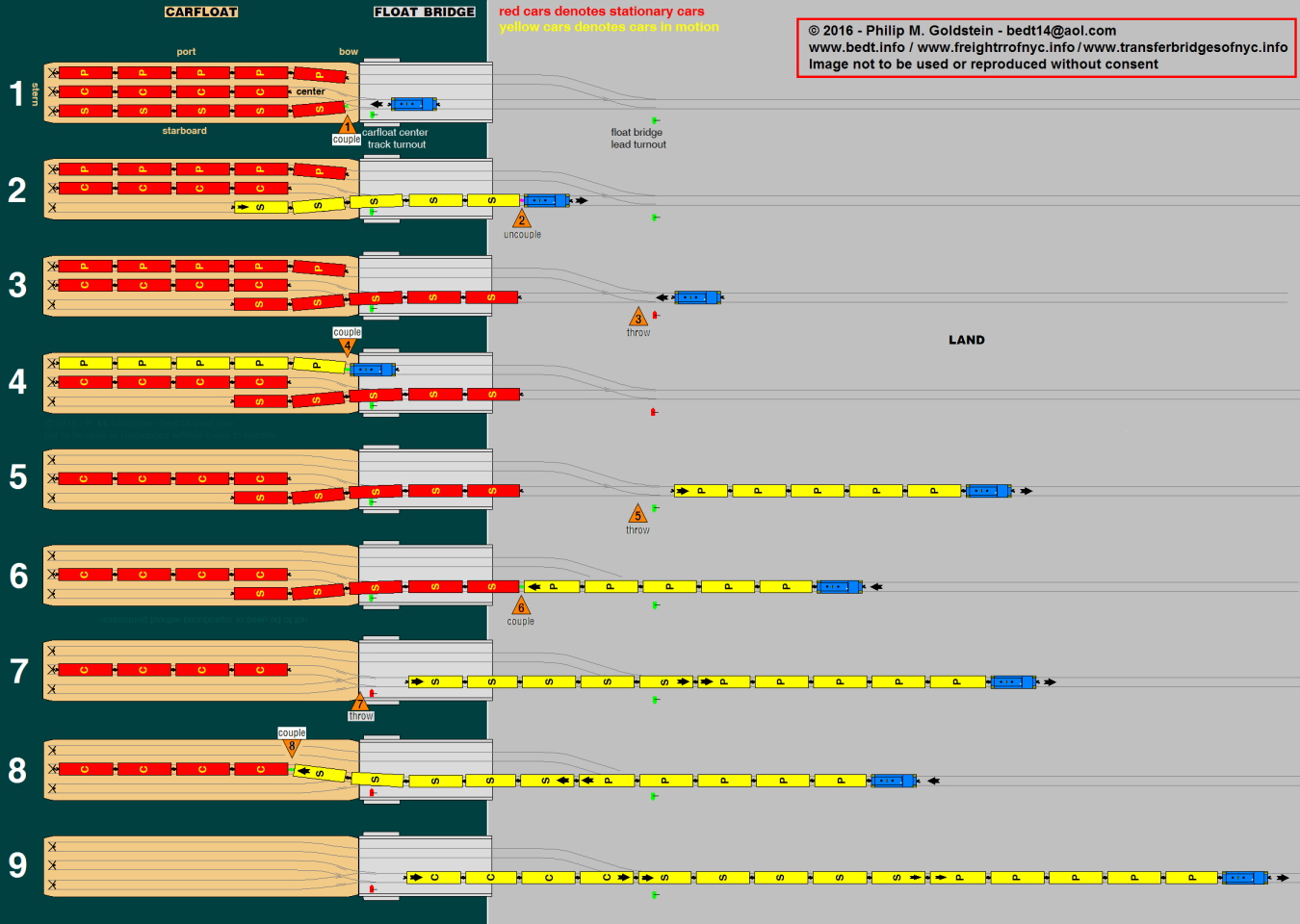
The procedure for unloading a carfloat can be viewed below. Please note, this procedure would apply in 99% of the time. In certain unusual cases, the procedure would be modified to accommodate an extra heavy or wide load or special circumstance. While the diagram below shows a pontoon float bridge, the procedure was the same at overhead suspended transfer bridges.
|
|
(Numbers in description correspond to the numbers in illustration.)
Locomotive is inched forward onto float bridge to
bring it into same height as carfloat. Carfloat is secured to float bridge
using method and appliances outlined in above
chapter. Locomotive then couples up to cut of cars on starboard
side track.
Locomotive pulls cut of cars on starboard side track half way off the carfloat and onto the float bridge lead; leaving part of the cut of cars still on float bridge and carfloat;
The locomotive uncouples from starboard side cut of cars, and locomotive continues past float bridge lead turnout. Turnout is thrown and aligned for port side track.
Locomotive heads forward onto port side carfloat track, and couples up to cut of cars on port side track.
Locomotive reverses direction, and pulls entire cut
of cars off of port side track of carfloat and past float bridge lead turnout;
and float bridge lead turnout is thrown and aligned
for starboard side track.
Locomotive proceeds forward pushing port side cut of cars and couples up to starboard side cut of cars.
Locomotive reverses direction and pulls combined port
and starboard side cuts of cars off carfloat to clear the turnout on float
bridge for carfloat center track, and points of
center track turnout are thrown and aligned for center
track;
Locomotive pushes combined port and starboard of cars onto carfloat, coupling up to string of cars on the center track of carfloat.
Locomotive reverses direction, and pulls entire cut
of cars (combined port starboard and center track cuts of cars) into
the yard.
Carfloat is now unloaded. To load carfloat, reverse procedure.
Would you like to see this operation in
real time? Visit my videos on YouTube
at:
.
| RETURN TO CHAPTER INDEX | RETURN TO MAIN INDEX |
.
| The Pontoon | Physics & Construction | Design Types |
| The DL&W Gantlet Track | Height Adjustments | Drawbacks to the Design |
| Installations: Tracking the Pontoon Examples | Return to Service: "Bush 2" becomes "Greenville 11" | |
.
The Pontoon type float bridges were commonplace at both large
Class 1 terminals on the New Jersey shore as well as smaller offline terminals.
This float bridge design was affordable, durable, easily maintained and most
importantly, the design worked.
According to French's book "The Development of the Carfloat
Transfer Bridge in New York Harbor" (1917), all float bridges located in
New York Harbor between 1866 and 1888 were pontoon supported Howe Truss
type. Unfortunately, it is not stated which railroad built the
first pontoon type float bridge in New York Harbor.
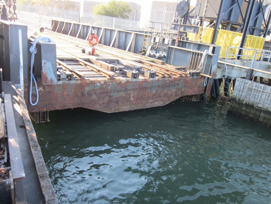
A pontoon type float bridge is nothing more that a bridge span hinged to the land on one end (inboard or land side) and a watertight box under the span at the outer or waterside end. But as simple as that sounds, it was more involved than that.
.
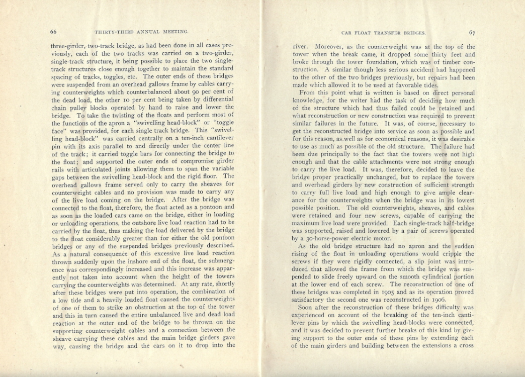
Supporting the outer end of the bridge on a floating pontoon is the simplest method that is both flexible and gives sufficient lift; and it was the first type introduced in the Port, circa 1866 to 1868 (Rohde, 1945; New York New Jersey Harbor Development Commission, 1920 - reference Transfer #10). In 1888 the problems involved in suspending the bridge from an overhead frame were solved by adding an "apron", as we will read in the suspended bridge chapter of this page, but the pontoon bridge was much less expensive and remained popular.
As pontoon float bridges were simple and economical to construct and easy to maintain, they were commonplace and could be found at almost every rail-marine terminal in New York Harbor; large, medium & small. The smaller independent contract terminals of the area relied on them almost exclusively. By the end of the 1970s the remaining operations at the port (with one exception: Greenville) reverted to the pontoon bridge for the sake of simplicity.
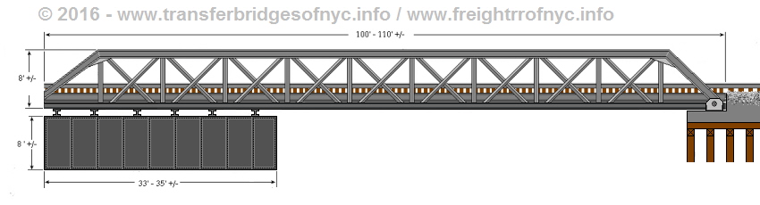
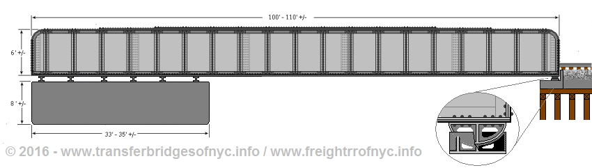
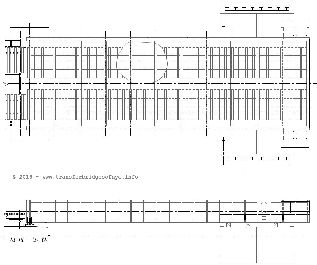
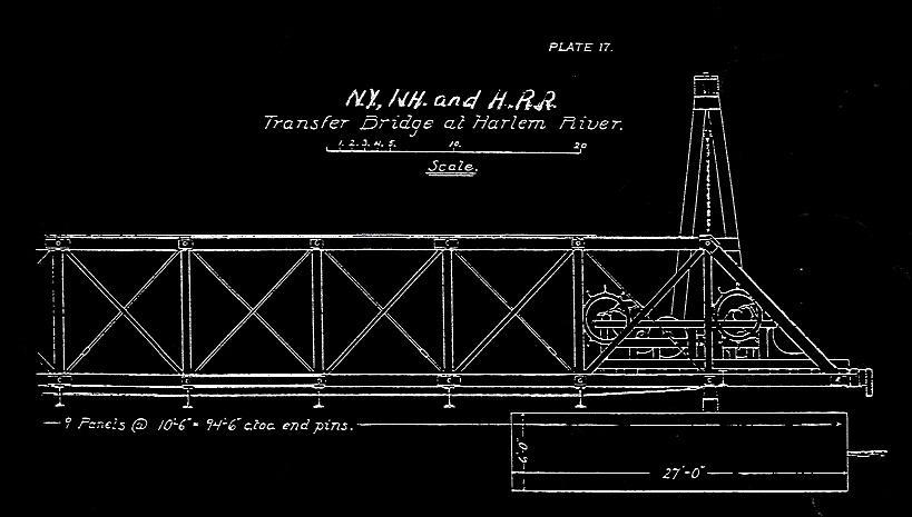
In its general appearance the pontoon type of transfer or float bridge does not appear complicated. Most designs average about 30 feet wide and 100 feet long.
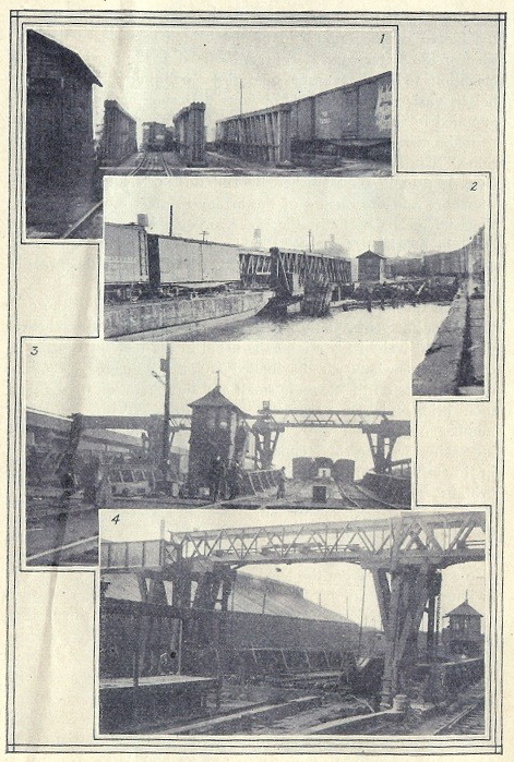
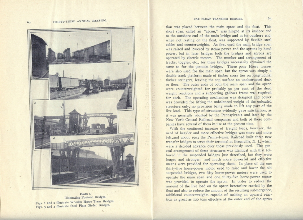
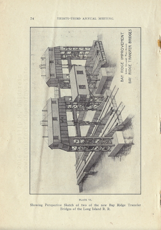
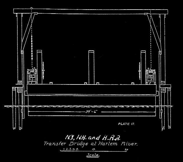
The Development of Carfloat Transfer Bridges in New
York Harbor, J. B. French - 1917
Plate I
|
1 & 2: Howe Truss type pontoon float bridges. |
P. M. Goldstein
collection
added 02 January 2012
.
| RETURN TO CHAPTER INDEX | RETURN TO MAIN INDEX |
.
Pontoon Physics and
Construction
This pontoon is of course, the key element of the design. In supporting the outshore end of the bridge, it automatically adjusts the float bridge for the tide, but it does much more then this (French, 1917). When the end of the bridge is attached to a carfloat, and freight cars roll over it, there is what engineers call a "live load reaction", meaning the bridge is suddenly called upon to support a much greater load. "Live load" refers to the variable weight on the bridge, as opposed to the "dead load", the weight of the bridge itself. In a properly designed fixed bridge, this force is carried down to the foundations, with little or no movement of the bridge structure.
With float bridges, things are different. If there were no pontoon and the bridge simply rested on the carfloat, all of the load would be applied to the carfloat, which would then sink until reaching a new state of equilibrium between the load and the carfloats buoyancy. But total reliance on the carfloat buoyancy is not advisable: it puts great strain on the carfloat the cause of the concentration of the load on one end, and if the carfloat sinks very far, there will be great strain on the connection with the float bridge due to the sharp angle. Also it could put the carfloat deck below water. And the sinking of the carfloat is uneven since one side is normally loaded before the other; if the carfloat must provide all the support it could list dangerously far. Imagine the scene in if the carfloat had to provide all the support!
Adding a pontoon to the bridge provides the needed additional buoyancy. As more weight is added to the pontoon, it begins to sink, but this additional displacement gives it more upward pressure where needed, automatically. As the load is transferred to the carfloat, it also sinks; the two tend to work in harmony. Thus pontoon bridges are inherently stable (French, 1917).
A pontoon in simplest terms, is a rectangular shaped tank sealed for the purpose of holding air and used in support of a waterborne object. It works by both utilizing displacement and buoyancy.
In the 19th Century, the initial design of the pontoon shown it generally constructed of wood planking caulked with pitch or tar and usually "coppered"; that is sheathed in copper sheets, much like a ship's bottom.
By the 20th Century, as metals took over as a preferred material for construction, the construction of the pontoon would evolve to be of steel plates, with overlapped seams and riveted. As the older wood pontoons reached the end of their service life, steel pontoons would even be used even under both existing or newly constructed wood Howe Truss bridges.
As metalworking technology further advanced in the 20th Century, the steel plates would come to be welded (replacing riveting) and this method remains so today when pontoons are when constructed for an existing and in service float bridge such as Greenville #11.
Graphic representations of the three types of pontoon construction as described above may be viewed under each type of pontoon span in the chapter below. Please note however, that any type of pontoon could have been found under any type of span.
In additions, there must be vertically driven pilings to keep the whole thing in line laterally, with side guides and chafing blocks, otherwise the bridge would float sideways with currents, tides and winds. These pilings are also referred to as "dolphins". Separate pile racks and fenders usually extended out into the river or bay to protect carfloat from floating ice and debris (Snow, 1901, 163).
.
| RETURN TO CHAPTER INDEX | RETURN TO MAIN INDEX |
.
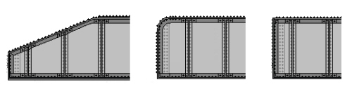
Types of Pontoon Float Bridges:
Span / Design Styles
Please note the illustrations below do not show winches, jacks and other equipment, and minor aesthetic differences varied by builder.
.
wood Howe Truss
Most 19th Century bridges used three wooden Howe trusses, with a top chord 10 feet above the tracks and the trusses about 16 feet apart center-to-center, with the center truss being midway between the two tracks. Some of the Howe Trusses were covered with vertical siding and caps shaped like gable roofs. This variation was used almost exclusively, at early overhead suspended separate apron locations to keep out the weather. A number of these wooden Howe Trusses lasted well into the 20th Century. In fact, the Baltimore and Ohio Railroad built one in the 1954 as a replacement for a steel girder bridge located at West 26th Street, Manhattan and it is in all likelihood the last wood Howe Truss float bridge constructed in the United States.
Wood was the preferred material by some railroads because of the salt water environment in New York Harbor, and because a wood truss tends to be flexible (Engineering News, 1890).
The bridges themselves were spans of wood Howe Truss design. Hardware such as the winches, toggles, angle braces and threaded rods were made of iron and steel. Three trusses ran lengthwise along the top of the span, with the one span running up the center.
This type of float bridge was found to be ideal for the purpose, as the wood was flexible enough to absorb the torsional stresses encountered during the loading and unloading of a carfloat.
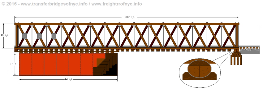
not to scale
.
Constructed with heavy wood timbers and wood decks that were creosoted for protection against decay. Threaded steel rods bound the upper and lower horizontal beams "chords" together and cast iron angle braces bolted to the corners of the diagonal trusses added additional strength.
Early designs used a wood "rocker" log as a hinge point on the bulkhead. This would evolve to a cast steel pivot anchor and socket.
As discussed in the above chapter, the Howe Truss graphic above shows the basics of the very early pontoon construction: wood planks, sealed with pitch and sheathed in copper plate.
By the turn of century, the iron or steel bridge was beginning to replace the wood Howe Truss, as the manufacturing processes for structural iron & steel components gained popularity and abundance. In time the "all wood" design evolved into steel pontoons of riveted or bolted construction and of bridge spans of riveted steel.
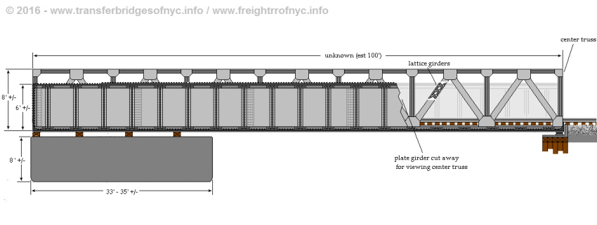
These new iron & steel designs would be available in two kinds: pony truss and through plate girder. With both types of steel float bridges, subtypes existed: both can be seen in three-girder and two-girder versions, although three truss float bridges were uncommon. None of these trusses or girders are essentially different from those used in regular bridges, except perhaps for their connections with the floor system. Both types of steel float bridges worked equally well, and were used throughout the New York area.
.
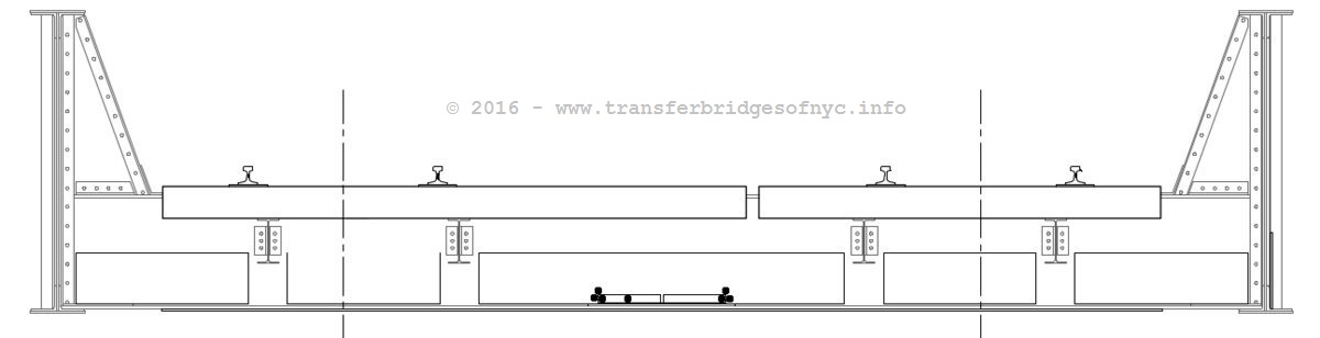
steel Pony Truss
|
. Toward the end of the 19th Century, steel pony trusses came into favor with some railroads, almost always with two strong outer trusses and no center truss (French, 1917, 60). But there was an exception: the float bridges at the New York, New Haven & Hartford Railroad's Hell Gate location were unusual in their design as they were constructed with a center truss member (making this a three truss subtype). While we have commonly seen a third plate girder installed at the center on the plate girder design type of pontoon bridge, a middle truss was not common on the pony truss. You can see this third truss in the blueprints and images in the Lifting Gallows chapter. Pony Truss and Through Plate Girder types were constructed of riveted iron and steel construction, with wood plank decks. Trusses were approximately 8 feet tall. These designs used steel "pin and plate" hinges or steel "pivot wheel and box" anchors on the bulkhead. Pony truss types also had two design variants: a two truss and a three truss. This means a two truss float bridge had a truss on the outer edges of the float bridge and no center truss. The three truss subtype had an additional truss running up the center of the float bridge between the tracks (like the wood Howe Truss). This pony truss above is shown with a riveted metal (iron and/or steel) pontoon. |
|
| .
.. |
|
|
. . |
|
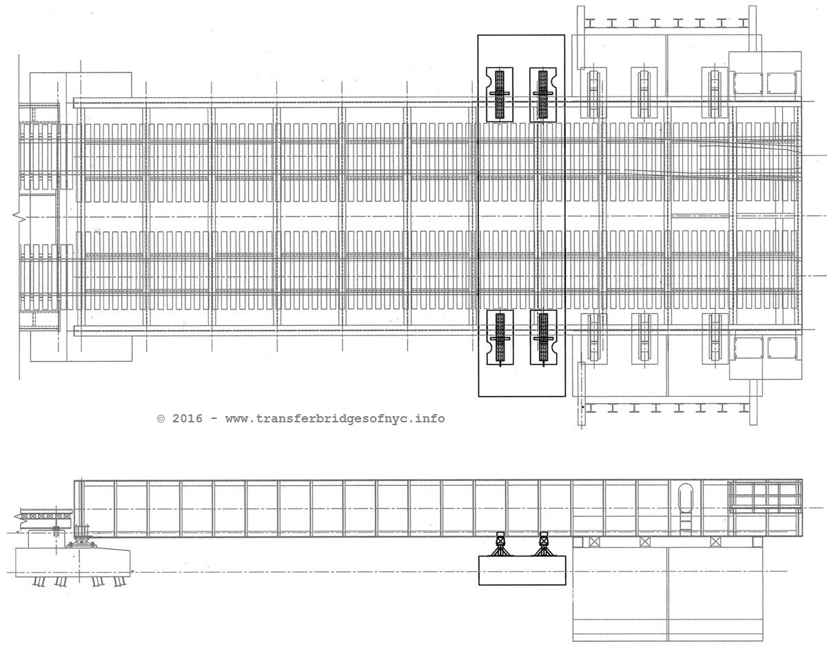
| Through Plate Girder types also had two design variants:
a two girder and three girder subtype. This means a two girder float bridge
had a plate girder on each of the outer edges of the float bridge and no
center girder. A three girder type had an additional girder running up the
center of the float bridge between the tracks. Girders were usually 4 to
6 feet in height. By far, the Through Plate Girder type was the most prolific
design of pontoon float bridge in the 20th Century.
The Thru Plate Girder float bridge above is shown with a welded steel pontoon. Also, the ends of the bridge varied by builder. Pony plate girder float bridges could be found with tapered ends, rounded ends, square ends:
. . Hybrid Designs: There was one hybrid pontoon type bridge span design. It was composed of plate girders on the outer edges, but with a single tall steel lattice truss down the center. To date, only the Jay Street Terminal in Brooklyn was known to have used this type of composite design, and no clear overall view of the bridge is known. Nor is the construction of the pontoon known. .
steel Through Plate Girder & steel Pony
Truss . |
|
.
| RETURN TO CHAPTER INDEX | RETURN TO MAIN INDEX |
.
The Delaware Lackawanna &
Western Railroad Gantlet Track
The Delaware Lackawanna & Western Railroad has been observed to have used a gantlet (also called gauntlet) style of track on its pontoon float bridges located throughout New York Harbor.
While this third set of rails would add nominal weight to the span, it had the benefit of relocating all moving parts of switch points, turnout and switchstand to the float bridge approach on land, which allowed the railroad to employ the use of a standard yard type switch throw, and do away with the condensed "in between track" switch throw so commonly used on other pontoon bridges.
It does not appear that this gantlet track required any modification of the construction design of the float bridge span itself, and all gantlet track construction was contained to the deck top. For viewing purposes, the gantlet track in the diagram below is highlighted in yellow:
.
.
| RETURN TO CHAPTER INDEX | RETURN TO MAIN INDEX |
.
.
Another Misconception: "Pumped Pontoons"
In those other parts of the United States that utilized rail-marine operations, the method to adjust the height of a pontoon type float bridge by pumping water in and out of the pontoon was tried and in some cases found satisfactory.
Unfortunately, many of those not knowledgeable with specific New York Harbor float bridge operations assume what was used in other locations, was used here as well. This is not so and this "pumped pontoon" method did not work well in regards to the operational needs of pontoon float bridge usage in and around New York Harbor (French, 1917, 61).
Several factors put forth for this pumped pontoon method not working in the New York Area of float bridge operation would be:
In winter, water would freeze disabling the pump and / or block pipes (and which would not be an issue on the warmer West Coast where this method was more prevalant);
Debris in the water: seaweed and flotsam in the river would lodge in the pump and pipes causing clogging;
The corrosive effects of salt water on iron pipes and in the iron & steel
pontoons would cause rust and scale to eventually plug up the pipe and corrode
pump seats;
but the most significant factor against "pumped pontoons" in New York Harbor:
The time involved in pumping water into or out of a pontoon. In those cases of float bridge use where freight traffic was not as high volume or hectic as it was in New York Harbor, the few extra minutes it took to pump water in or out of a pontoon was not crucial. In and around New York Harbor however, speed was of the essence and where rail-marine operations swung on the tide, the arrival of perishables for market, express shipments, consigned freight to meet a train and the duty shifts of a tugboat; a tug's crew needed to get its carfloats moored, drilled, and released with as little wasted time as possible.
.
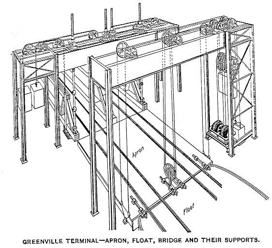
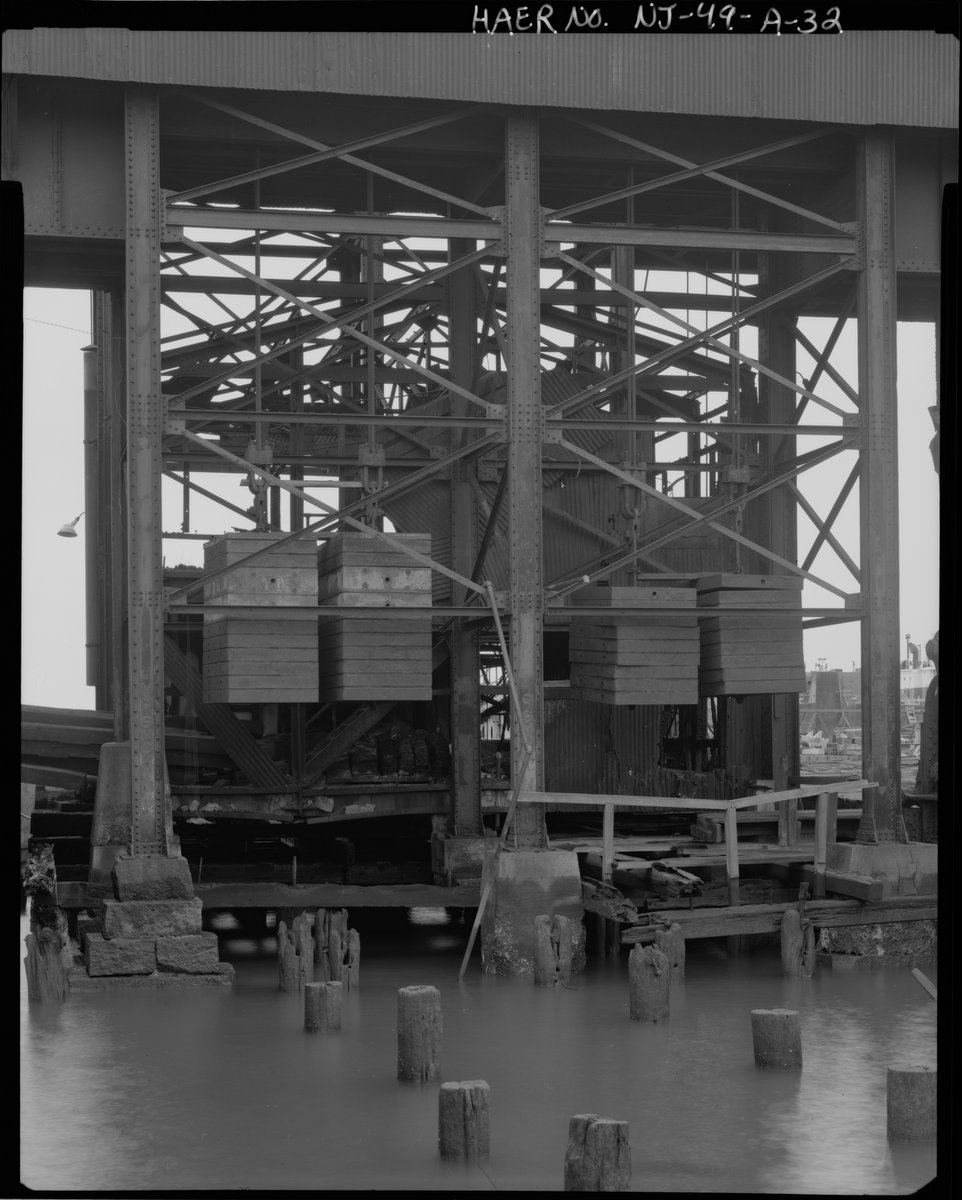
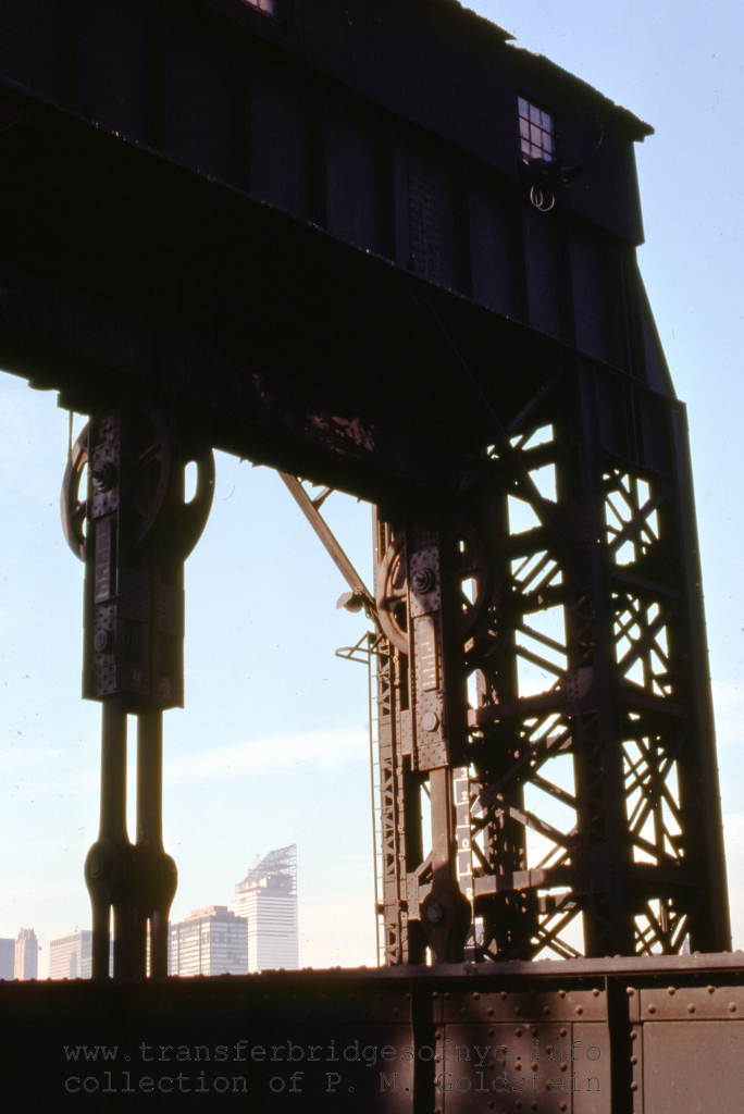
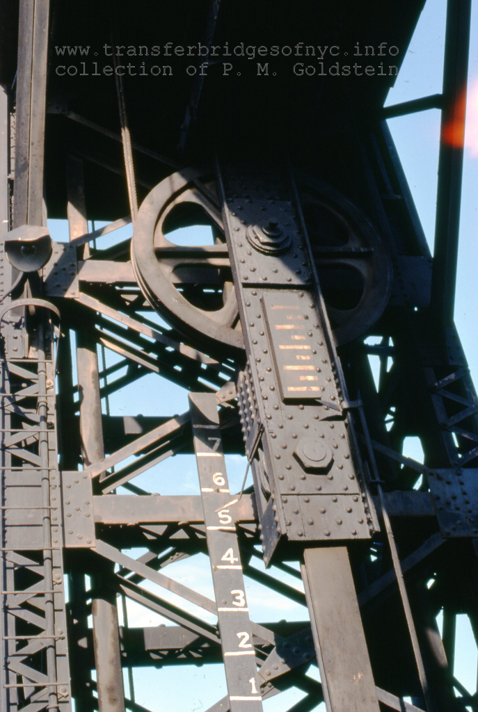
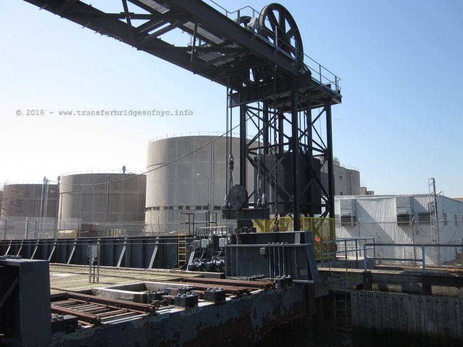
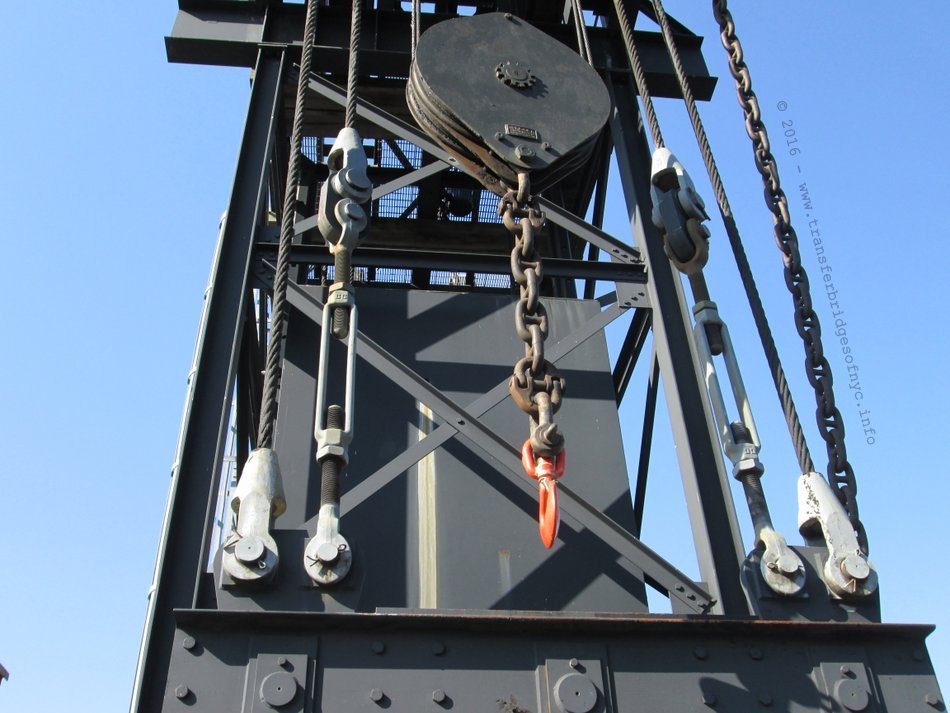
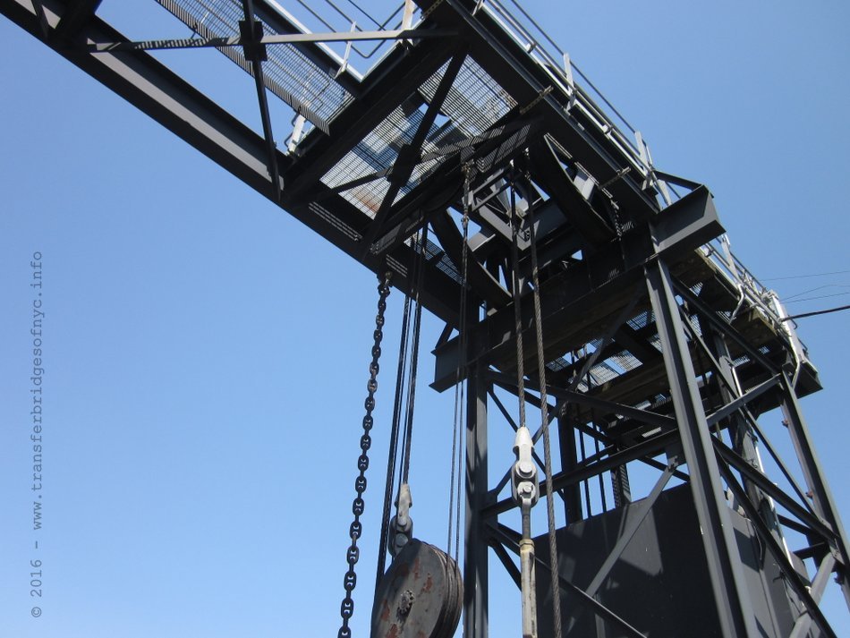
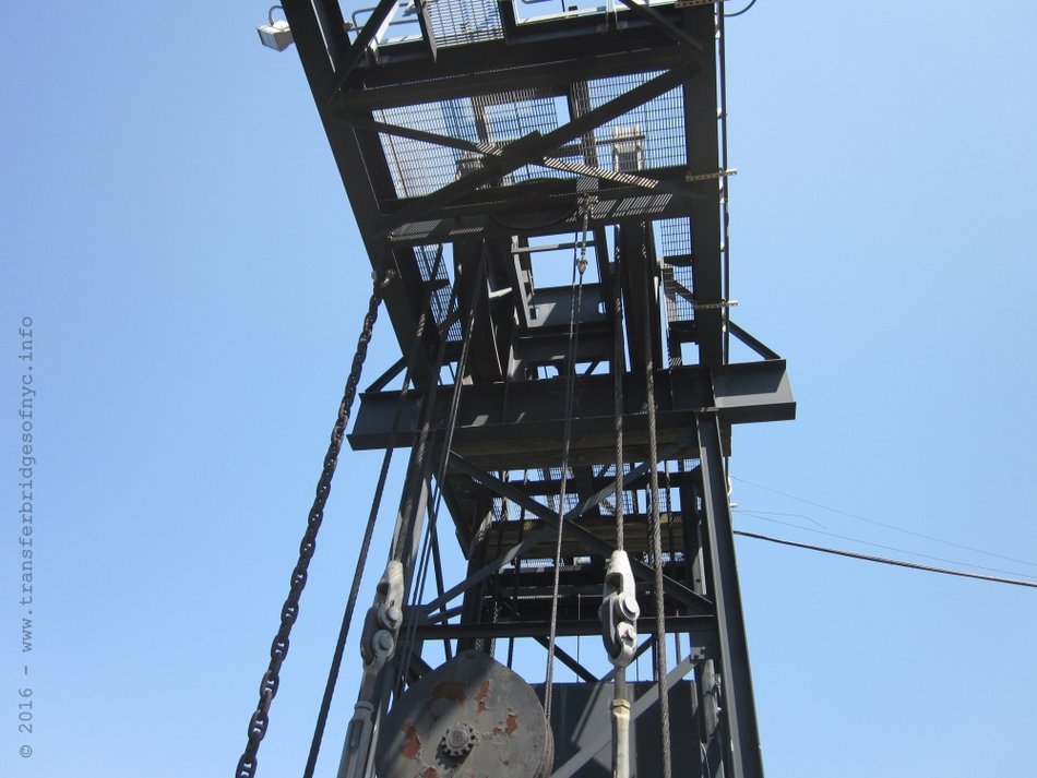
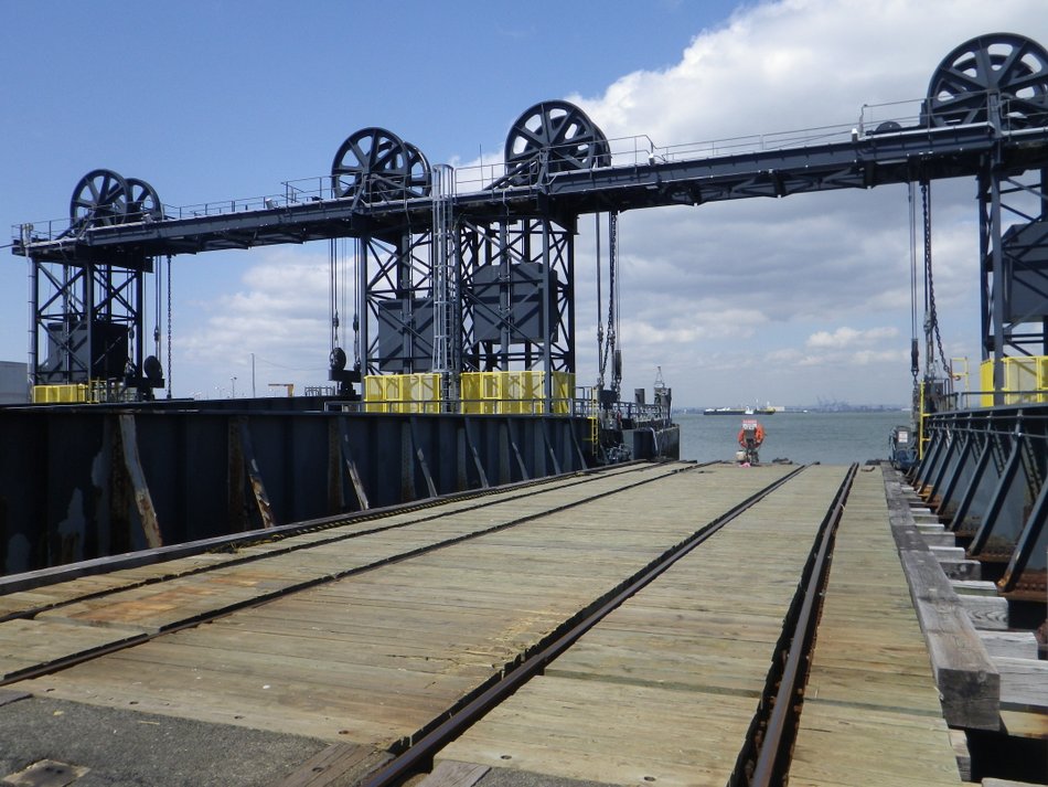
Lifting Gallows.
Therefore, the earliest pontoon float bridges as constructed in New York Harbor utilized overhead lifting gallows. They are often seen in older photographs of pontoon bridges at New York, and these gallows were also used to raise the float bridge for maintenance or replacement of the pontoon.
An important aspect to the operation of float bridges is the method of adjusting the float bridge to match the corresponding height of the carfloat to allow the toggle bars to meet the sockets on the incoming carfloat. Almost always, the float bridge would need to be raised or lowered to meet the deck height of an incoming carfloat. While the pontoon adjusts the bridge height automatically for the tides, it does not do so for variations in height above water of the carfloat itself. This could be due to the size of the carfloat, or the weight of load upon it. It goes without saying empty freight cars are lighter than loaded ones and some loads are lighter than others.
In the initial design of the float bridge, pontoon buoyancy would be calculated and the size of the pontoon allotted for the float bridge to ride higher than the average loaded carfloat. But, there would be those occasions when the float bridge is lower than the oncoming deck of a high riding or "light" carfloat or a slow leak / seepage in a pontoon.
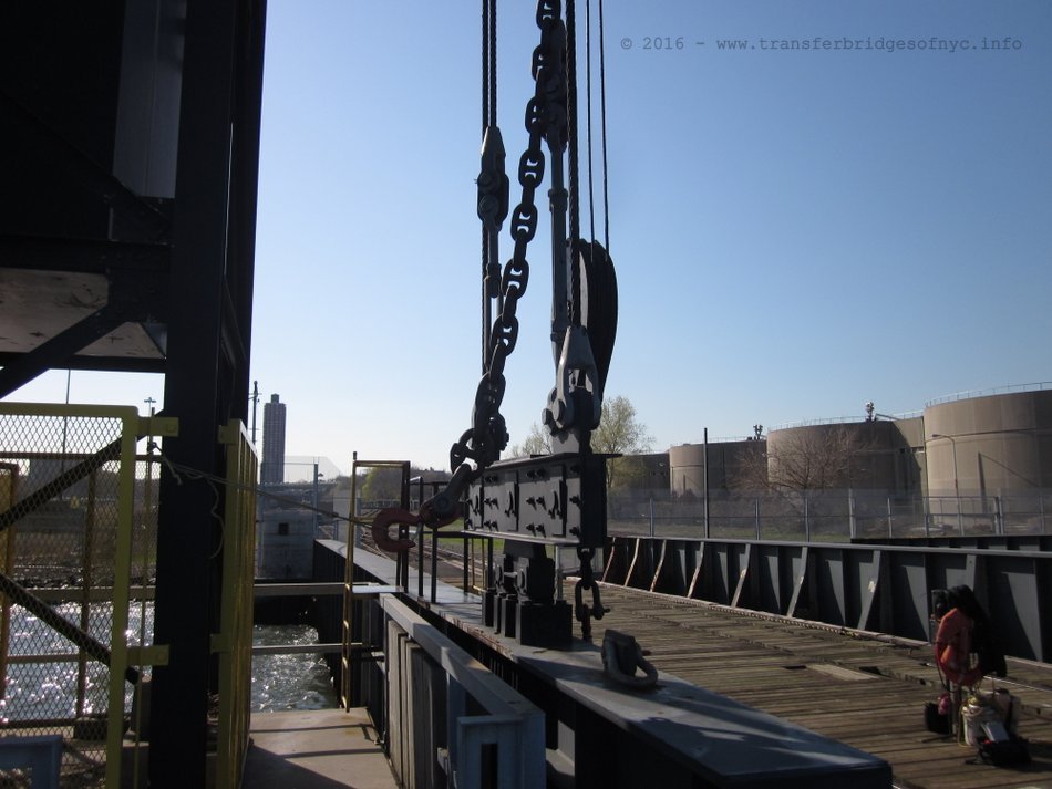
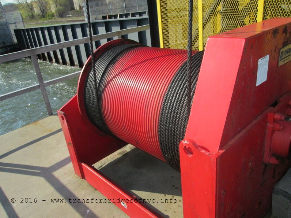
In those cases, the overhead gallows gave a structure in which to raise the float bridge. Most gallows were equipped with one, two or three pulley blocks or chain falls to raise the float bridge as seen in the Brooklyn Navy Yard image below. Another method used was with a hand turned, reduction geared winch mounted on the bridge with the cable fixed to the overhead gantry as seen in the NYNH&H design below.
It must be understood here and now, that the gallows were never used to raise or lower the float bridges during an actual loading of carfloat or carry a live load. (Snow, 1901, 162). Once the float bridge was mated to the carfloat, the cables or chain were slackened.
As construction methods progressed, steel lifting gallows became common place and both plate girder and various truss types were seen. Again, the gallows were only used for lifting or lowering an empty bridge to meet the height of an incoming carfloat, or to service the pontoon under the span. After the bridge was mated "toggled" to the carfloat, the lifting chains slackened and detached.
The overhead gallows could also be used to raise the bridge to service or change the pontoon as needed.
|
|
|
|
.
. It has long been wondered why the overhead gallows fell out of use and in most cases; removed altogether from all but the very few locations around New York Harbor. While not conclusive, it is postulated that as the earliest pontoons were constructed of wood planking, with the seams sealed with pitch and then the pontoon sheathed in copper. As the pitch would dry out, the seam would seep water making the float bridge ride lower and lower in the water. Also, the wood despite treatment would absorb some amount of moisture over time, thereby making it less buoyant. Also, with all the planks having at least two caulked seams (the top and bottom of the plank), it would stand to reason that the seams would need to be recaulked on some sort of basis to prevent leaks.
So, the overhead lifting gallows was a necessity in both regular maintenance and repair to early float bridge design using wood pontoons.
However, just after the turn of the century when iron & steel working was improved and perfected and likewise riveting and welding along with it; steel pontoons became the design choice. Steel pontoons were by design less prone to seepage or leakage, and tolerated being bumped and crashed into by debris or ice better and stood a higher chance of remaining watertight despite that abuse than its wooden pontoon predecessors.
As such, with the proliferation of the metal pontoon, the overhead lifting gallows were no longer needed to assist a leaky or maintenance intensive pontoon and were removed through attrition and replacement / modernization of a float bridge. This might have more merit than we realize, as if one references the images of pontoon float bridges throughout New York Harbor taken by and after the middle of the 20th Century, the original pontoons built in the late 19th Century as well as the float bridges themselves, had reached the end of their expected service life and were replaced. And by proxy the overhead gallows had become an unnecessary fixture, were removed and no longer seen.
Again, this is hypothesis and not conclusive.
|
|
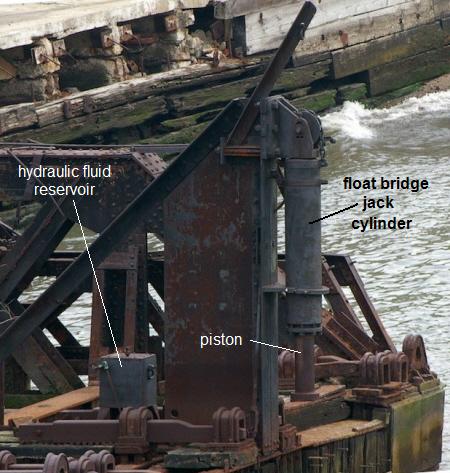
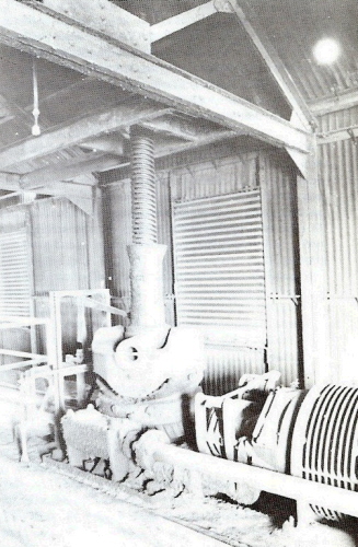
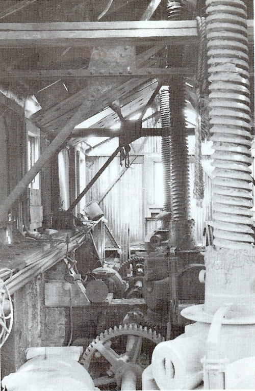
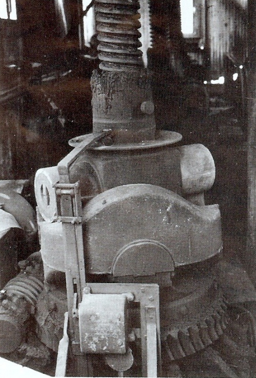
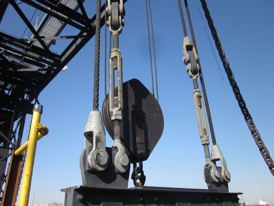
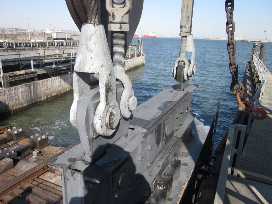
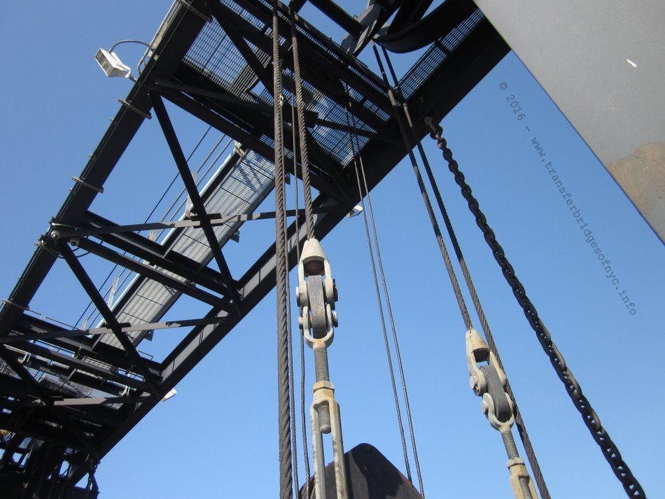
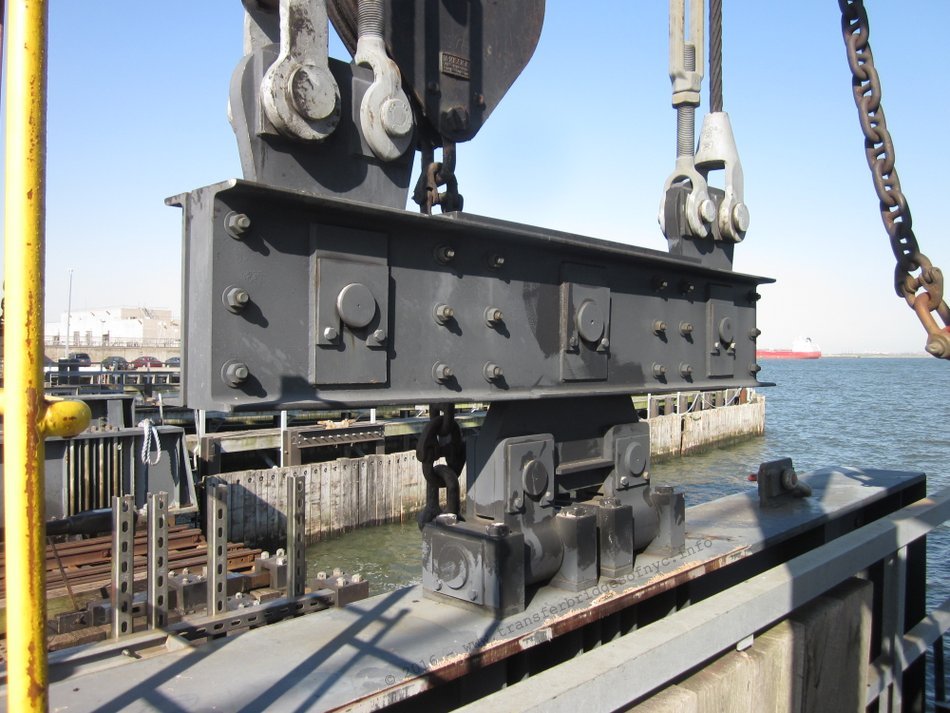
Enter the Hydraulic Float Bridge Jack A later innovation did away with the gallows altogether. A hydraulic jack with a downwards facing extendable piston was mounted to the outboard end (or face) of the float bridge. This apparatus, known as a "float bridge jack" was rigidly mounted to either a steel A shaped frame between the tracks (bearing a remarkable close resemblance to an italic A ) or in the case of wooden Howe truss design, the float bridge jack would be fastened to the end of the center truss. In its position of mounting, the float bridge jack would overhang the end of the float bridge. When a high riding carfloat was positioned under it, and flush up against the bridge, some square wooden blocking (usually cast off sections of railroad ties) would be placed on the deck of the carfloat and under the jack taking up and much space as possible. Then, the jack would be pumped, thereby extending the piston down, taking up the remaining space, when it would contact the blocks and press down on them and likewise against the deck of the carfloat. As the carfloat was more buoyant than the float bridge, the float bridge would "rise" out of the water by the necessary distance, and now allowing the decks of the carfloat and float bridge to be in horizontal alignment. this would in turn allowing the toggles to be inserted into the carfloat toggle receptacles to keep the carfloat & float bridge in lateral and vertical alignment. .
|
|
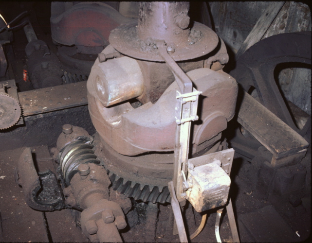
How Did It Work?
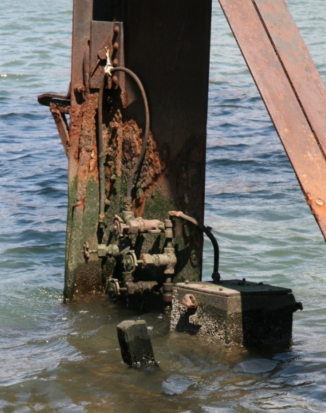
Paul Strubeck noticed there is no handle mounted on the jack cylinder to pump it. That is because there wasn't one. Behind the A-frame on the bridge deck was a small weathertight reservoir (usually a box), containing the hydraulic fluid and with a pump handle.
Most often you can't see this hydraulic fluid reservoir in images because the photographer was standing on the bulkhead or adjacent pier taking pictures and the side girders of the float bridge blocked the view.
Upon special request, John McCluskey took a large array of images of the BEDT Pidgeon Street float bridge (pontoon / pony truss) as well as Paul Strubeck of the float bridge at the Brooklyn Navy Yard (former BEDT North 9th Street float bridge). Both were able to take images showing the hydraulic fluid reservoir and valving, and can be seen in the images above and to right. .
Wood blocking was stacked to take up most of the empty space between the carfloat deck and bottom of the piston.
On one side of this reservoir was a small manually operated pump handle. According to Joe Roborecky, the handle was usually nothing more that a simple bar of steel stock that was flattened on one end to fit in the socket receptacle. The handle receptacle can be seen in the image at upper right. The handle was designed to be removable and taken out of the pump when not needed, and usually left on the bridge. The handle was then pumped which forced hydraulic fluid in the cylinder and thereby extending the piston. Once the space was taken up and the piston rested on top of the wood blocking, the piston began lifting the float bridge to the desired height.
In the images above, the connecting hoses dry rotted long ago, but you can see one of the fittings on the side of the box. The image at right shows one of the hoses dangling. The fittings on the jack cylinder in the image above are in shadow and difficult to discern, and the cylinder is completely gone from the float bridge at BNY. One hose ran from one hand pump to a fitting located near the top of the cylinder and another hose ran from the other pump to a fitting near the bottom of the cylinder.
By opening a certain combination of valves and then pumping the handle, would draw hydraulic fluid from the reservoir, through the hose into the jack cylinder and extend the piston downward. Now, to get the piston to retract, those valves would be closed and another set opened redirecting the fluid to another port on the hydraulic cylinder, and by pumping the handle, would retract the cylinder. Hand valves protected the operation in each direction, but the specific order and valves that needed to be opened and closed would be specific to each bridge. At this time we do not know which combination of valves needed to be opened and/or closed to do what, as there are no operating versions of this type of mechanism left to inspect.
By closely examining other images (of which we have dozens) of BEDT float bridges, you can discern the hydraulic fluid reservoir with pump handles at the foot of the jack A-frame. However it should be noted that this was a rarely needed operation, as by design of the pontoon, the float bridge almost always rode higher than the carfloat, and only a locomotive was needed to be inched forward on the float bridge to weigh it down to match the height of the carfloat.
In referencing the current and only surviving pontoon float bridge in operation in New York Harbor of the New York New Jersey Rail at Bush Terminal, the frame and float bridge jack have been removed altogether from the end of "Bush 2" float bridge. Now if only we can figure out why there is a pulley & chain on the top of the jacks!
.
.
Present Day
Normal practice at present is to design the pontoon so that the buoyancy of such is so that when the float bridge is free, it sits high enough upon the water to accommodate an empty carfloat.
When a carfloat that is drafting more (riding lower in the water) than usual, and is brought in to the float bridge, the bridge is lowered by running weighted "idler" or "reach" cars or even loaded freight cars, or the locomotive by itself (when heavy enough), onto one track of the bridge until that side of the bridge sinks down enough to allow a toggle bar to be run into the toggle bar receptacle on the carfloat. Then the locomotive is backed off and run over to the other track, until that side sinks to the level of the carfloat. At which point the other toggle bars can be slid into their sockets. This method obviously puts a lot of strain on the toggle bars and requires a floor system designed so that the bridge can flex a great deal. At this point, once all the toggle bars are inserted into the toggle boxes on the carfloat, the float bridge and carfloat have been toggled together, and the hawser lines drawn tight.
With this design, the buoyancy of the pontoon tends to lift the inshore end of any but the highest (unloaded) carfloat. This is a good feature during loading as it provides the maximum assistance in supporting the live load, and in counteracting any tendency of the carfloat to tip sideways, but it also means that the carfloat is virtually "hung up on the toggles" when loaded and ready for a tugboat to take it away.
According to an interview conducted by Tom Flagg with Frank Dayton in 1993, (at the time of interview Mr. Dayton was employed by the New York Cross Harbor Railroad and was formerly employed at the Brooklyn Eastern District Terminal prior to its dissolution), simply pulling out of carfloat that is "hanging on the toggles" causes two kinds of damage: "it can bend the toggles, and knocks the hell out of the float bridge when it bounces after release… but mostly we avoid it". The proper procedure ("by the book operation") is to first make sure the carfloat is properly "trim" that is balanced side to side. The carfloat is then "unpinned". This is accomplished much like it was pinned: by running a locomotive onto the bridge until there is no more weight on the toggles. Then the toggles are unlocked and withdrawn by the bridgemen, who also releases the lines. The carfloat is then either pulled out by a tugboat or moored with lines to the dolphins if the tugboat is to come later. Dave Pearce recalls that the same procedures were used on the Lehigh Valley Railroad when he was employed in its Marine Department..
.
| RETURN TO CHAPTER INDEX | RETURN TO MAIN INDEX |
.
As carfloat in traffic at New York increased, the pontoon bridge became a bottleneck (Engineering News, 1911, 771). When most carfloating was to serve pier stations, with carfloat of only fourteen or sixteen lightly loaded less-than-car-load (LCL) freight cars, the pontoon bridge worked well enough. But in later 19th Century, freight car weights became heavier and capacities increased, and three track interchange carfloats carrying more cars was introduced. Raising and lowering the pontoon bridge to adjust it to the more variable heights of these carfloats was a slow procedure, and heavier cars had to be loaded with more care to avoid transferring weight too fast. At tidal extremes, the steep grade on the float bridge and the sharp angles at its ends made the work difficult or in some circumstances even impossible.
If the angle between land and float bridge, or between the float bridge and carfloat was too sharp (the flatter the better), the couplers of the freight cars being rolled on or off the carfloat might slip over each other, which could lead to disaster. If the cars made too hard an impact on the carfloat and the resulting shock broke the mooring lines holding the carfloat to the float bridge, the result would be sudden gap between the carfloat and float bridge. If this happened, the wheels of the freight car could fall into the gap and much more hard work would be needed to restore operations. Another cause of delay in the winter months was floating ice, which got wedged into the slip around the pontoon and prevented it from moving freely. This is not to say that during the rest of the year did not see issues either: silting of the slips made dredging necessary, which meant a complete removal of the bridge and its pontoon (Snow, 1901; French, 1917).
Permit records kept by the New York Department of Docks show of that dredging was necessary approximately every three years on the Hudson River waterfront of Manhattan, but at some other locations dredging had to be scheduled once a year. According to Droege (1912, 225), when maintenance of the pontoon was necessary, the bridge was hoisted up (e.g.: to an overhead gantry) at high tide; then at low tide the pontoon was disconnected and floated out. The present day procedure is to move a floating crane into position to lift the float bridge. (Dayton, 1993).
Obviously, the solutions to these problems was to get rid of the pontoon altogether and in suspend the outshore end of the float bridge in some manner. But finding a suspension system that provided the flexibility and the automatic support of the pontoon is not such a simple engineering problem as it may seem. As we will learn by reading the suspended apron portion of this pages, it would be the Pennsylvania Railroad that developed this solution.
Another drawback, as it was soon observed in the corrosive salt-air climate of New York Harbor, the wooden Howe Truss spans had better endurance and longevity, but while they had that attribute, they were more laborsome to produce. Each Howe truss bridge was assembled and tested for fit, then disassembled, and most if not all the wood components subjected to pressure treating with creosote. Then, the bridge reassembled again. All assembly and disassembly being by hand!
Steel bridges were ultimately cheaper to manufacture by quicker methods such as riveting, and later by welding. By nature of this, aside from minor dents and damage, is was more cost efficient to replace a steel float bridge and / or the pontoon at the end of their respective service lives.
In general observation, the life span of an all steel float bridge was approximately 25-30 +/- years with routine scheduled maintenance (and not taking accidents into consideration); whereas a Howe Truss could last 50+/- years or more. Key word here being (as with anything mechanical) "routine scheduled maintenance".
Even as late as the middle of the Twentieth Century, and after steel was the predominate material of construction for float bridges, the Baltimore & Ohio Railroad still preferred wood Howe Truss type float bridges! It would even go as far to replace a steel bridge at its West 26th Freight Station in Manhattan, with a new wood Howe Truss type in 1954! Another would appear at the Baltimore & Ohio St. George Terminal on Staten Island, but it is unknown at this time whether this particular wood Howe Truss was merely a transplant (the most likely scenario) or whether it was another new construction (unlikely but not impossible).
Considering that the Baltimore & Ohio Railroad could have simply transplanted a steel bridge to either of these location, but did not, is a testament to the success of the wood design despite the advancement of steel as a preferred construction material in bridge spans.
.
| RETURN TO CHAPTER INDEX | RETURN TO MAIN INDEX |
.
Tracking the Pontoon Type
Float Bridges
The pontoon type float bridge, of which was once one of the most popular, prolific and ubiquitous designs of float bridge, has been reduced to just a handful of survivors.
Being the simplest design, they were relatively simple to maintain. The pontoon type float bridge was used by the largest Class 1 railroads right down to the smallest offline terminals and in one case, and even a private industry (Proctor & Gamble - Port Ivory, Staten Island). They could be constructed and floated to their designated location by carfloat, with the pontoon to be installed in a separate unit.
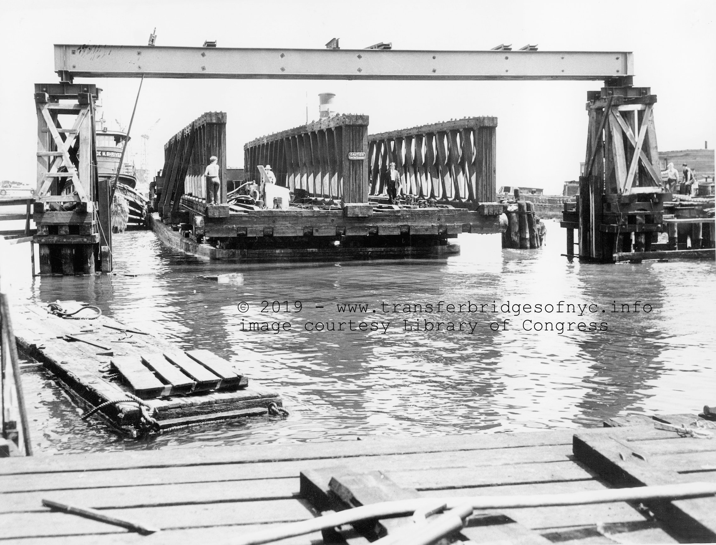
Baltimore & Ohio Railroad "George M. Schriver"
believed to be either West 26th Street, Manhattan or St. George, Staten Island.
.
.
Most of the larger railroad terminal facilities such as Pennsylvania Railroads' at Harsimus Cove, the New York Central at Weehawken and New York, New Haven & Hartford at Oak Point began their rail-marine operations with pontoon bridges. As traffic increased and technology advanced, those pontoon types were gradually replaced with electrically operated overhead suspended transfer bridges of the most modern design at the time of their construction.
..
.
Manhattan
New York Central - West 69th Street
In Manhattan, there are two surviving pontoon float bridges:
One of these is the steel pony truss located at West 69th Street. It is abandoned in place. Despite its less than desirable state, this is the only location in all of New York Harbor where one can view three different types of transfer bridges. This pontoon float bridge sits between the partially burnt overhead suspended separate apron Howe Truss (overhead gantry was burnt down and the transfer bridge is now partially sunk) and the only relatively intact Overhead Suspended Contained Apron "French type" transfer bridge.
|
|
| .
. |
|
|
| .
. |
|
|
| .
. |
|
|
.
.
Baltimore & Ohio - West 26th Street
The only other pontoon type float bridge located in Manhattan is the last remaining wood Howe Truss pontoon type float bridge in all of New York Harbor, and can be seen at West 26th Street and West Street, Manhattan.
This former Baltimore & Ohio Railroad span, was built new in 1954 for this location and was restored in 2006. It can be seen from all four sides as it is part of a public dock. The nature of the surrounding park makes visiting this float bridge a must, and it is where one can almost completely walk around and on the float bridge, to study its detail and revel in its design! It is well preserved and must be seen.
.
Brooklyn
Bush Terminal
The only pontoon type float bridge still in service in all of New York Harbor was the former "Bush 2". As of December 2012 the now rehabilitated, relocated, reactivated and renamed "Greenville #11" (see New Jersey sub-chapter below).
"Bush 1" however remains in partially sunken state at the foot of 51st Street.
.
Brooklyn Army Terminal
South of Bush Terminal at this location is the abandoned former Erie Railroad's West 28th Street (Manhattan) Freight Station through plate girder (two girder subtype). This float bridge was relocated to the Brooklyn Army Terminal by New York Cross Harbor Railroad in 1991 and used briefly when First Avenue was under reconstruction, preventing use of the street trackage leading from Bush Terminal 50th Street float bridge "Bush 2" to the Brooklyn Army Terminal. At some point, this float bridge was torn or floated away from its bulkhead anchor and now sits a few yards off shore with it's pontoon end still afloat, but land end submerged. This bridge is unique as its girders are tapered at the outshore end, which is similar in shape to French's contained apron main span.
Unfortunately, the closest "legal" viewing of the Brooklyn Army Terminal and 65th Street float bridges is best done from the public 58th Street pier, (entrance just north of the Brooklyn Army Terminal gate on First Avenue), so bring binoculars and a zoom lens.
.
Brooklyn Navy Yard
Under the Brooklyn Navy Yard gantry is the former Brooklyn Eastern District Terminal North 9th Street float bridge, relocated to this location 1983.
Next to the Brooklyn Navy Yard gantry is an abandoned and totally sunk float bridge. This derelict bridge is only seen during low tide.
.
New York Dock - Fulton Terminal
And finally, the abandoned New York Dock Fulton Street float bridge. Originally two float bridges at this location, one was scrapped decades ago.
.
Queens
Brooklyn Eastern District Terminal - Pidgeon Street
In Queens, there was the former Pidgeon Street float float bridge of the Brooklyn Eastern District Terminal. This particular steel pony truss float bridge was installed here circa 1958, and replaced another steel pony truss of different design at this same location. It lies abandoned just off the bulkhead in its original location. Access is limited. It has been learned as of August 2016, this float bridge is no longer on the waterfront and is presumed scrapped.
.
New Jersey
New York New Jersey Rail - Greenville
"Bush 2" Bridge (51st
Street, Brooklyn, NY) gets recalled to service and relocated to Greenville,
NJ
In October 2012, Hurricane Sandy caused irreparable damage to the last operating unit (Bridge #11) of the overhead suspended transfer bridges built by the Pennsylvania RR at Greenville, NJ. As soon as the storm surge receded, NYNJ Rail officials along with engineering firms began to assess the damage. It was decided the overhead suspended transfer bridges were not viable to repair (images and further details in Overhead Suspended Separate Apron - Greenville Damage & Demolition below).
To expedite a return to carfloating service not to mention keep NYNJ Rail employees from being laid off; it was decided to relocate the 51st Street pontoon float bridge at Bush Terminal "Bush 2 Bridge" in Brooklyn, NY to Greenville, NJ. The Bush 2 Bridge was no longer being used, with NYNJ Rail having relocated their Brooklyn base of operations to the 65th Street Yard after the activation of the 65th Street Transfer Bridges, not 4 months prior to the hurricane.
Once the existing but severely damaged Greenville transfer bridges were demolished and area cleared, a small trestle was built from the shoreline to a few dozen yards off shore and a new concrete bulkhead anchor was poured. As part of its return to service, the float bridge was also rehabilitated. The engineers involved installed:
New rocker heel bearings,
New heel bearing connections,
New electric hawser winches, replacing the four manual winch wheels,
New secondary pontoon to make bridge sit higher in water, and
The centerlines of the tracks on the span also needed
to be widened to match the spacing of the current Greenville Yard tracks.
(Bush Terminal trackage due to its era of construction, had its trackage
more closely spaced than todays accepted design
standards),
.
Weeks Marine was contracted to pick up the float bridge in Brooklyn, NY and haul it across New York Harbor to Greenville, NJ; where it was installed in its new location. It has been renamed "Greenville #11 Bridge".
It should be noted, that only 52 days elapsed from Hurricane Sandy inflicting her damage to the restoration of carfloating service. This restoration of service required, but not being limited to: site studies, permit filings, demolition, debris removal, excavation & grading, pile driving, concrete pouring, fabrication, rigging & lifting, repair and rehabilitation of the Bush 2 Bridge, rail & turnout laying, physical installation of hardware, electrical runs and testing. Quite a remarkable achievement considering the amount of involvement of bi-state governmental agencies and firms involved. Saying nothing of the weather being damp and rainy, but the work continued throughout never the less. Kudos are absolutely necessary to all those that were involved in this project!
Giancarlo Schiano and Kevin Ciampi, two of the many professional engineers involved; took images of construction and the pontoon bridge being relocated and furnished plans. They are a nice addition to the chapter, and help show the ongoing viability of the pontoon type float bridge. They are used here with permission and are not to be reused without express consent.
|
|
| .
. |
|
|
| .
. |
|
|
|
|
|
|
| .
. |
|
|
| .
. |
|
|
| .
. |
|
|
| .
. |
|
|
| .
. |
|
|
| .
. |
|
|
| .
. |
|
|
| .
. |
|
|
| .
. |
|
|
.
.
.
The Overhead
Suspended Electrically Operated Separate
Apron
.
| The Challenge | The First Solution | J. A. Bensel Mini-Bio | Development of the Design |
| Automatic Live Load Counterweighting | F. L. DuBosque Mini-Bio | The Friction Dampener | Span Designs |
|
Historic American Engineering Record (HAER) - Greenville Transfer Bridges |
Operations | Installations: Tracking the Separate Apron | |
|
Greenville, NJ Damage & Demolition of Transfer Bridges 9½, 10, 11, 12 |
|||
.
.
As we read in above, the pontoon provided the required flexible support for the outer end of a float bridge, and it was the first method used at the Port of New York. As we have also read, the pontoon type float bridge had some disadvantages which became more prominent with increases in traffic and in car weight. The Pennsylvania Railroad was the railroad most blessed (or afflicted, depending on your position on the railroad) with heavy traffic, and the Pennsylvania Railroad was the first railroad at the Port of New York to build a successful transfer bridge that suspended the bridge instead of floating it (Snow, 1901; Engineering News, 1890).
To do this, required some way of avoiding the torsional motions resulting from the weight and from pushing freight cars onto carfloats. For example, if the outshore end of the bridge was suspended by a pair of heavy wire ropes (cables) or chains, then consider the distribution of forces when loading cars onto one side of the carfloat tied to the end: all the stress would be placed on that side, but due to the chain it would be unable to lower, meaning the buoyancy of the carfloat would no longer be able to help support the live load. In fact, the tendency of the carfloat to twist would put more stress on any such rigid support. Neither a simple winch and cable system, or a combination pontoon and suspension system, would adequately provide both stability and flexibility; or at least that was the belief of New York port engineers (although such systems did prove satisfactory results at other ports, perhaps because they had lighter traffic).
.
The First Solution - John
A. Bensel
J. A. Bensel, began as assistant engineer for docks & terminals of the Pennsylvania Railroad. He devised and built a successful suspension system in 1888 and his basic method became the standard at New York. He used rigid screw rods to lift or lower the end of the bridge proper, in conjunction with counterweights on cables that carried most of the dead weight of the bridge, and then added a flexible apron about 25 feet long between the end of the bridge span and the carfloat (Bensel, 1888: Snow, 1901).
An important point about transfer bridge nomenclature that should be made: in other regions of the United States, the term "apron" referred to the whole transfer bridge. At New York and other Eastern ports, the apron was a continuation of the deck of the bridge, carrying the tracks but with a very flexible support structure (here, wood beams strengthened by truss rods) designed to allow twisting, and easy to repair upon wear. At its inshore end, it was supported by the outshore end of the bridge proper, to which it was hinged, and at its outer end Bensel's apron was supported by a "friction arrangement" that would support the weight of the end itself, but left it free to move up or down when a load was applied. The apron thus followed the carfloat motions but kept them from affecting the main bridge. The live load coming onto the apron was supported by the carfloat.
In operation the bridge and apron would be raised so as to be a little above an incoming carfloat, then, by releasing the friction device, the apron would lower enough to allow the toggle bars to be slipped into the toggle bar receptacles on the carfloat. As we saw in Part I of this series, getting the pontoon type of float bridge into position to bridge a carfloat was much more cumbersome (Bensel, 1888; French 1917). The suspended type of transfer bridge also avoided the problem of leaving the carfloat "hanging on the toggles" after loading, since the operator could lower the transfer bridge to compensate for the sinking of the carfloat during loading.
As illustrated below, Bensel's suspension system for the transfer bridge proper consisted of two parts. About 90% of the weight of its outer and was supported by cast iron counterweights acting through strong cables (wire ropes) guided by pulleys suspended in an all overhead framework or "gantry". The hoisting mechanism, which was separate from and in addition to the counterweight system, worked as follows. The outer end of the bridge proper was hung from eyebars, the upper ends of which were attached to 4 inch outside diameter threaded rods (i.e.: screws) that were raised and lowered by the rotation of a nut supported in a self-aligning bearing (a kind of gimbal mount) fastened to the framework above the bridge, shown in upper right.
So, the Pennsylvania Railroad commenced with construction of these overhead suspended separate apron type transfer bridges in New Jersey at their Harsimus Cove freight terminal, just a short distance north of their passenger ferry terminal.
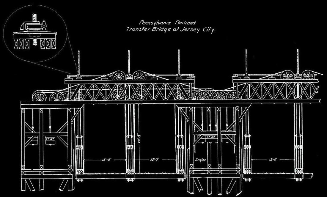
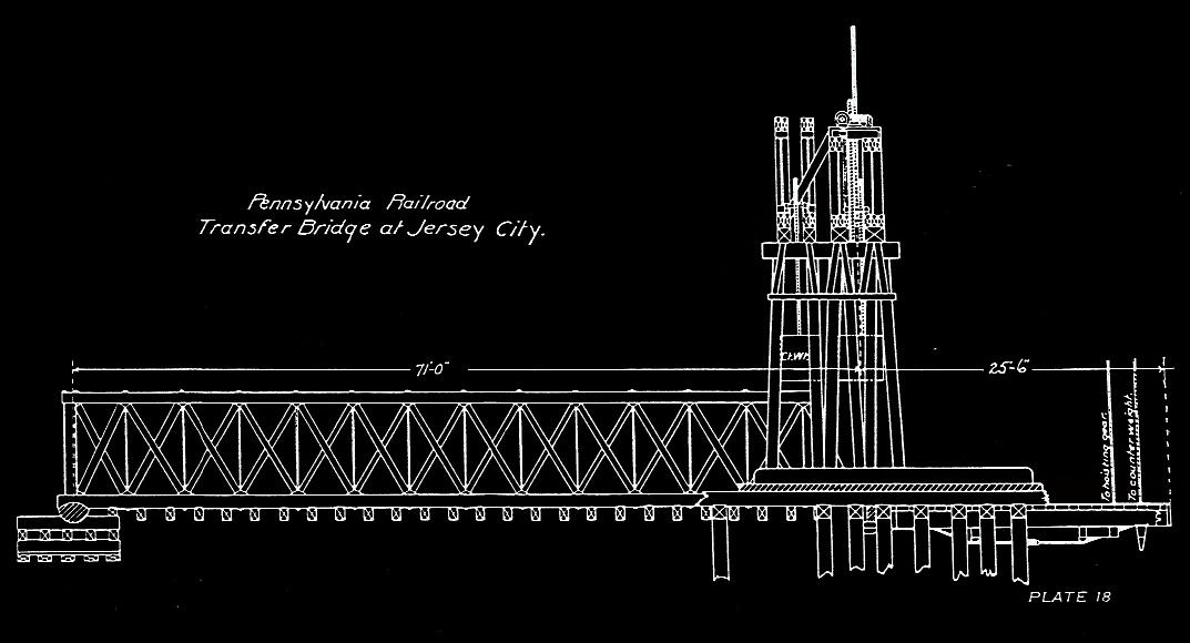
The gimbal mount allowed the threaded rods to change their angles slightly as the bridge rose and fell. The nuts in turn were rotated by a worm gear arrangement turned by a power driven shaft also located overhead:
|
|
|
Threaded Rod / Screw & Gimbal Mount Power Nut |
.
An improvement that appeared soon afterward, was the suspension of the outshore end of the apron from an additional separate counterweight that just about balanced the dead load at that point, leaving the apron to move freely with the carfloat. This replaced the "friction arrangement" mentioned by Bensel (Snow, 1901; French, 1917). It also made the bridge costlier to construct, by having to add a second set of pulley sheaves, counterweights, and overhead truss supports.
To analyze this system, imagine a string of freight cars being pushed onto the bridge. At first, its weight is supported by the shore pivot. As it is pushed further out onto the transfer bridge, more and more weight is placed on the main suspension. The counterweight will support none of this live load; if it were the only support, the bridge would sink under the live load. Therefore, the eyebar - screw rod - nut system, which cannot sink in response to the added weight, automatically takes all of the added weight (as it was designed to, though in the early designs it could not actually lift the bridge) and transmitted through the overhead gantry and down the tower supports to the foundation.
As the freight cars are pushed onto the apron, part of the load continues to be supported by the screw rods via the apron hinge. The rest of the load is transferred to the carfloat by the toggle bars, at which point the carfloat now begins to sink (and twist) while taking on its new load. The apron takes up the difference in height thereby created, and in the early suspended bridges, the operator could not adjust the either the apron or the main bridge when they were loaded.
This transfer bridge design worked well, especially after the worm gear shaft was connected to a steam engine instead of being operated by hand cranks as it was at first! In about 1892, Snow described Bensel's bridge design further and stated that it worked much more quickly than the pontoon types and was less subject to damage (Snow, 1901). The success of this design led the Pennsylvania Railroad to construct more float bridges of this design, and the New York Central Railroad would built several of essentially the same design as well.
At an early date, the steam engines that originally powered the suspension type transfer bridges, were replaced by electric motors. As a result, railroad men coined a popular term for these type of transfer bridges and called them "electric bridges", to distinguish them from the unpowered pontoon type float bridges).
Before closing out this chapter, it should be noted that John A. Bensel had quite a history involved with engineering:
 |
|
| John Anderson Bensel was born August 16, 1863.
He graduated from Stevens Institute of Technology in 1884, and became an assistant engineer with the Aqueduct Commission. Then he worked for the Pennsylvania Railroad, and from 1889 to 1895 was in charge of constructions on New York City's North River waterfront. In 1896, he married Ella Louise Day and the same year he became Consulting Engineer of the Philadelphia Water Department. In 1898, he became Chief Engineer of the New York City Dock Department, and in 1906 was appointed a Dock Commissioner. From 1908 to 1910, he was President of the New York City Board of Water Supply and in 1910, he held the office of President of the American Society of Civil Engineers in 1910. He was appointed as New York State Engineer and Surveyor from 1911 to 1914, at which time he entered politics. During World War I 1916-1918, he was in command of the 125th Battalion of Engineers of the U.S. Army during World War I and held the rank of Major. He died of myelitis on June 19, 1922, in Bernardsville, New Jersey. |
.
Aside from the strengthening of components over the years, the next major improvements came when the Pennsylvania Railroad built several transfer bridges at its new Greenville, NJ Terminal about 1903 - 1906. This terminal was planned to be the largest waterfront railroad terminal in the United States, and it was intended that these transfer bridges would handle the heavy interchange traffic across the harbor to the New York, New Haven & Hartford Railroad.
The float bridges constructed at Greenville were longer than the earlier models, with 30 foot aprons, heavier trusses and more powerful electric motors: two 50 horsepower motors to operate the main span and one 35 horsepower motor for the apron (Railway Age, 1905; duBosque, 1915). These float bridges were the first in the harbor with suspension systems strong enough to actually lift the entire bridge under a live load (Engineering News, 1911, 771). This allowed the bridge operator to continually adjust the bridge and apron as necessary during actual loading.
These Greenville float bridges used three wooden Howe truss for each bridge. See page 399 of Railway Age below for drawings.
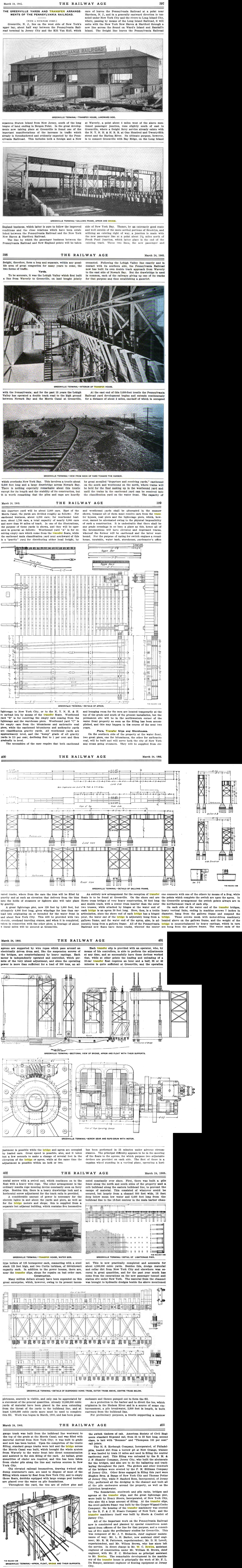
Railway Age - March 24, 1905
.
The New York, New Haven and Hartford Railroad followed suit by constructing four float bridges of at their Oak Point Facility in the Bronx to a similar design, but they opted to use steel throughout, including steel plate girder bridges (full description in Engineering Record, 1910).
Also unlike the earlier float bridges at Greenville, the overhead supports for the suspension systems at Oak Point were placed in two separate gantry structures, built entirely of steel instead of being housed under one large roof and enclosed wood structure (transfer house). The design continued to prove to be successful and New York, New Haven and Hartford Railroad constructed four more float bridges of identical design a few years later at the same Oak Point location.
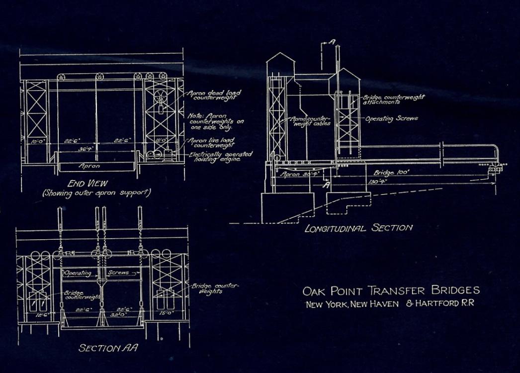
The Development of Carfloat Transfer Bridges in New
York Harbor, J. B. French - 1917
Plate II
P. M. Goldstein
collection
added 02 January 2012
.
.These improvements speeded up operations at the float bridges and helped to cope with the still increasing weights of the then modern freight cars entering service. All of the Pennsylvania Railroad float bridges at Greenville and some at their Harsimus Cove facility were later rebuilt to this design:
Pennsylvania Railroad, Harsimus Cove, NJ - 1979
T. Flagg photo
added 03 January 2012
.
.
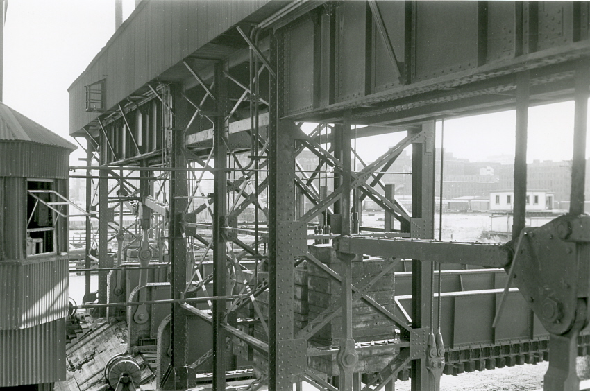
Pennsylvania Railroad, Harsimus Cove, NJ - 1979
T. Flagg photo
added 03 January 2012
.
.
Automatic Live Load
Counterweight - Francis L. duBosque
Perhaps the most interesting improvement to occur to these transfer bridges, was the method of supporting all of the live load on the apron, thereby greatly relieving the stresses encountered by and partially transferred to the carfloat. Another engineer in the employ of the Pennsylvania Railroad: Francis L. duBosque, reported later (discussion following Burtner & Tingey, 1927) that about the year 1900, that the railroad (PRR) had conducted tests with the new steel carfloats of the type entering service, and intended for carrying large quantities of cars.
It was found that in placing the live load on the new carfloats, which happened with all existing aprons, was placing heavy stresses on the new longer carfloats. Therefore, some method had to be found, to support the outer end of the apron. What was needed was a counterweight that would automatically and instantly take up the weight added by the rolling of the freight cars (live load) onto either side of the apron, without either lifting or lowering the apron end.
Today, we might imagine that this task would require employing a computerized system with sensors, but the actual solution was entirely mechanical and quite ingenious. Credit for this apron live load counterweight system seems to belong to Frank L. duBosque himself, judging from his patent (US #14,313; November 24, 1914) and a descriptive article written by him in 1915. Like Bensel and other engineers of his generation, duBosque did not explicitly claim credit for his ideas in his published description.
DuBosque's explanation (1915, 577) is as follows :
"The ends of a wire rope are made fast to the sides of the outer end of the apron, the rope passes over head around pulleys and downward until it's a loop rests in a sheaves; on the shaft carrying this sheave is a similar sheave over which a wire rope passes, one end of which is attached to the drum of a hoisting engine and the other to a counterweight resting on the ground. When the apron is light it may be raised and lowered by the hoisting engine but when a load comes on, it is counterbalanced to the extent of the counterweight".
.
In other words, in normal operation the counterweight never actually lifted off the ground, but was only used to the extent needed automatically. As the drawing below illustrates, in practice things were a bit more complicated on account of the need to support the apron at the center, as well as its sides.
.
|
|
The solution was to wrap one cable around a center sheave
on the apron, lead its two ends up to the overhead pulleys, across, and then
down to the suspended shaft and around and up and back out to support the
two ends of the apron, one end of the cable at each side. Then, that cable
and its pullers were duplicated, as insurance to give greater capacity. Weights
were also hung from the suspended shaft to stabilize it and give permanent
counterweighting to the dead load.
It should be noted that this system was used only for the apron suspension, not for the main bridge. While it clearly does allow automatic counterweighting and allows the apron to respond to twisting, it is not clear how (or if) the system allows the outer end of the apron to automatically rise and fall as a whole in following the carfloat movements. All this sounds reasonable, but without seeing it actually work, it remained a mystery to most of us. Fortunately, we have an professional engineer among us (actually two) Kevin M. Ciampi and Giancarlo Schiano. Both of these gentlemen are more than somewhat involved in transfer bridge design in New York Harbor. In one of their symposium papers, an animated .gif file was created to demonstrate duBosques' Live Load Counterweight action. They have courteously provided the animation for use in this chapter. In the animated file, the dead load counterweight is seen in white. The live load counterweight system is shown in yellow. . Please note: This animated file is copyrighted and not to be reproduced or redistributed without the express consent of either K. M. Ciampi, G. Schiano or the authors of this website. |
|
| .
.. Needless to say, all the aforementioned improvements as devised by duBosque, made these new transfer bridges faster acting and more efficient than ever before. They could unload and reload 22 cars from a three track "transfer" or "interchange" type carfloat in 35 minutes or less, instead of the hour and a half normally required with earlier float bridge designs. Yet, by the time these new improvements were described in duBosque's article, they had already been made obsolete by an equally ingenious and even more efficient design: The Overhead Suspended Contained Apron transfer bridge, designed by James Benton French, as will be discussed in the next section of this page. |
||
.
.
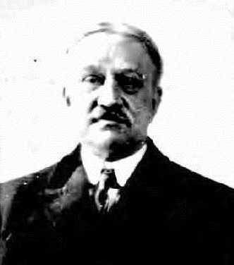 |
Francis L. duBosque - mini-biography |
|
Francis (Frank) Lebrun duBosque was born in Philadelphia, PA on January 24, 1864. He entered the employ of the Pennsylvania Railroad of February 9, 1891 as a draughtsman in the office of the Superintendent of Motive Power of the New Jersey Division. He was appointed to the position of Assistant Engineer on February 1, 1892 and on June 1, 1917, was appointed to the position of Superintendent of Floating Equipment of the New Jersey Division. He was also a member of the Society of Naval Architects and Marine Engineers. He passed away in 1940. |
..
..
Back to the Original Design
- The Friction Dampening Device
Returning to the transfer bridges, apparently during World War II a different system for suspending the aprons was installed on some of the bridges. In a fact this was actually a reversion to the original method of supporting and dampening the movement of the apron. This device, for all intents and purposes, is a dampening device utilizing friction to absorb movement. It is a sleeved cylindrical device connected from the top of the center bridge girder to the deck of the apron, and by such mounting, holds the apron in position, along with regular counterweights to support the dead load.
The Pennsylvania Railroad's blueprints call this a "power suspension" system. The blueprint for this bridge (seen below) does not show any electric or air connections to the piston, and actual inspection of the remaining piston in place suggest they were never powered.
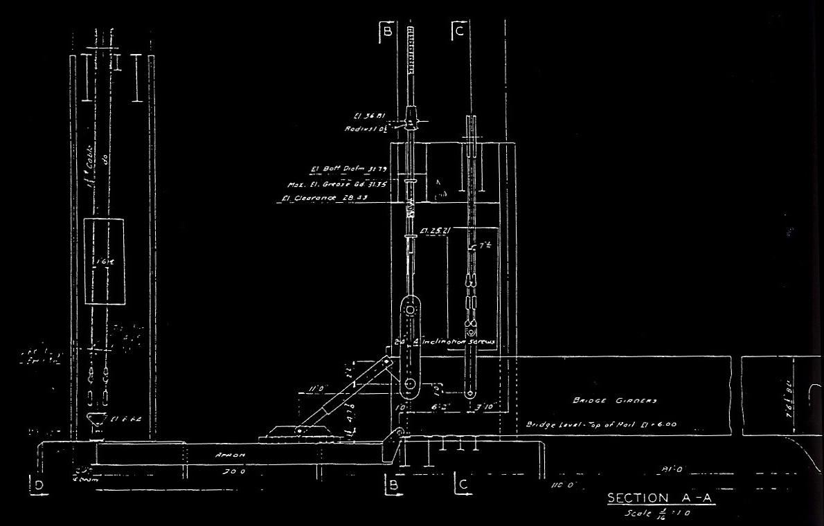
Pennsylvania Railroad - General Plan Transfer
Bridge #10 - November 10, 1924
Pennsylvania Office of Engineering, Bridges and Buildings
added 03 January 2012
.
|
|
The only remaining friction dampening device was located
on Greenville transfer bridge #11, which was still in use prior to being
razed as a result of damage to the support gantries incurred by Hurricane
Sandy on 29 October 2012.
Images taken in May 2009 by P. M. Goldstein, reflect that Bridge #10 does not have this device, nor does #9½ by this date. Neither did bridges #13 & #14. However according to an image dated 1994 in the collection of Paul Strubeck, brackets for the friction dampener can clearly be seen on bridge #9½ and these brackets can be seen in images of bridge #9½ and #12 in the Historic American Engineering Records (seen below) as well. But those images taken of bridge #10 does not have these brackets! Why is this device omitted from some bridges and not others? It should be noted at this point that bridges #9½, #11 and #12 were constructed by American Bridge, and bridges #10, #13 and #14 were constructed by McClintic - Marsh, which predating the American bridge spans. Therefore it is surmised, that the spans constructed by American Bridge were so modified to mount the friction devices, possibly because these spans were newer. Leaving this friction dampening device topic for just a moment, in order to support this McClintic - Marsh / American Bridge design difference theory: the McClintic - Marsh built bridges: numbers #10, #13, #14 had pin & plate bulkhead anchors, while the American Bridge constructed versions had rocker pivot & pivot box bulkhead anchors. While something as minor as this bulkhead anchoring system might be trivial in nature, it clearly reflects different design philosophies between the two different bridge manufacturers. Therefore, if this hypothesis is correct; bridge #10 should have the additional duBosque mechanism still in place. Unfortunately we cannot examine bridge #13 & #14 for this mechanism as they collapsed and subsequently were demolished in 1994.
|
The transfer bridges at Greenville were rebuilt at least twice over the years. For example, in the 1920's, most of the wood Howe trusses were replaced with steel plate girder bridges. The following blueprint is dated 1924 for #10 bridge. Reconstruction was completed in 1925. Clicking on the top image will bring you to a high resolution scan. Use the back arrow on your browser to return you here.
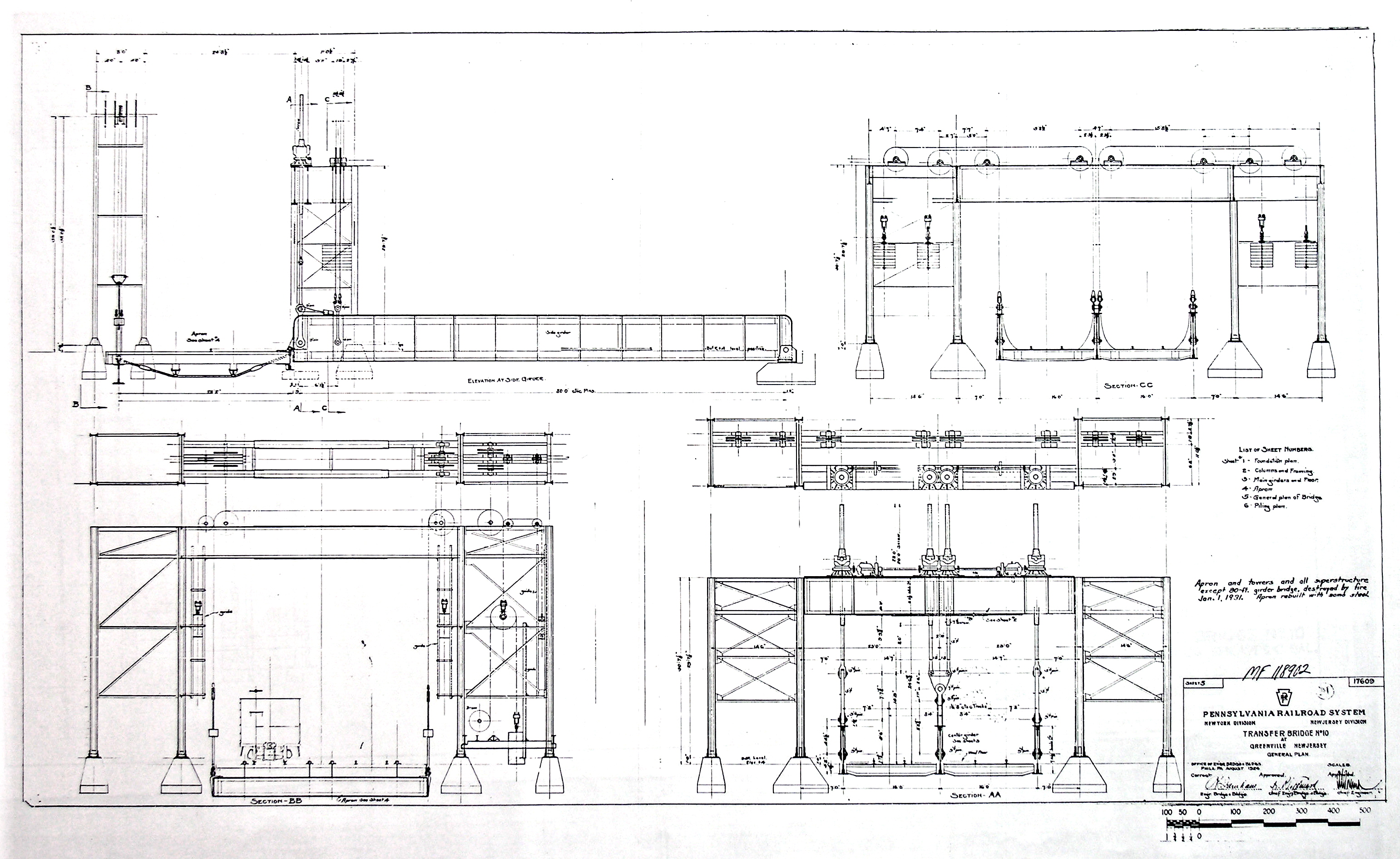
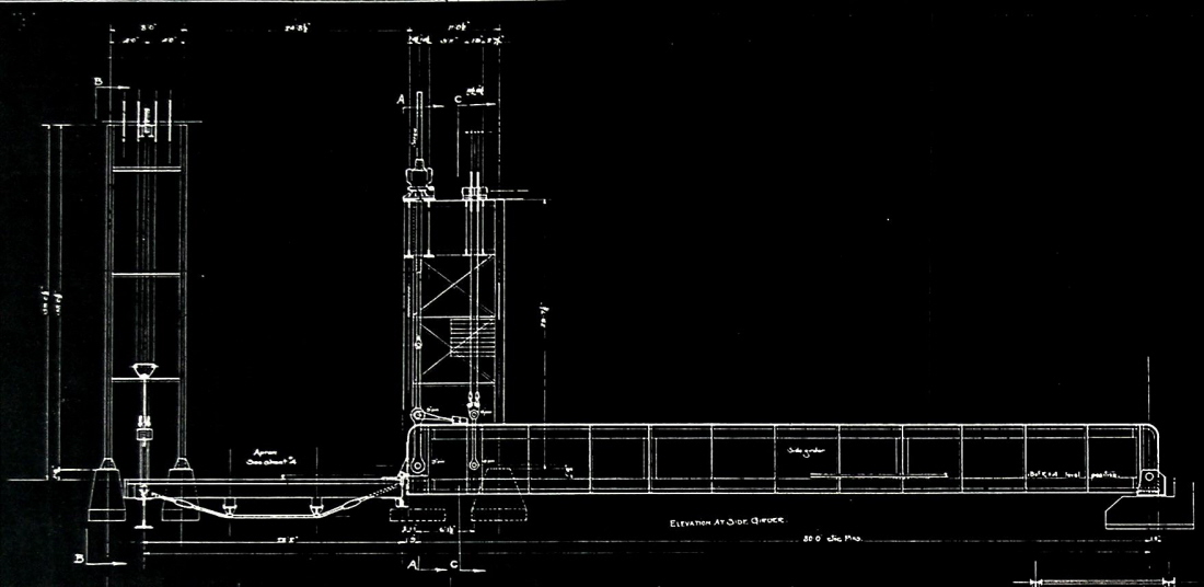
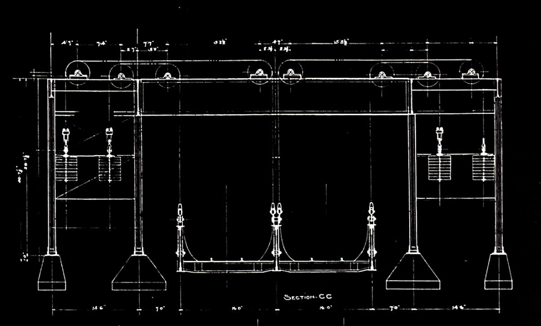
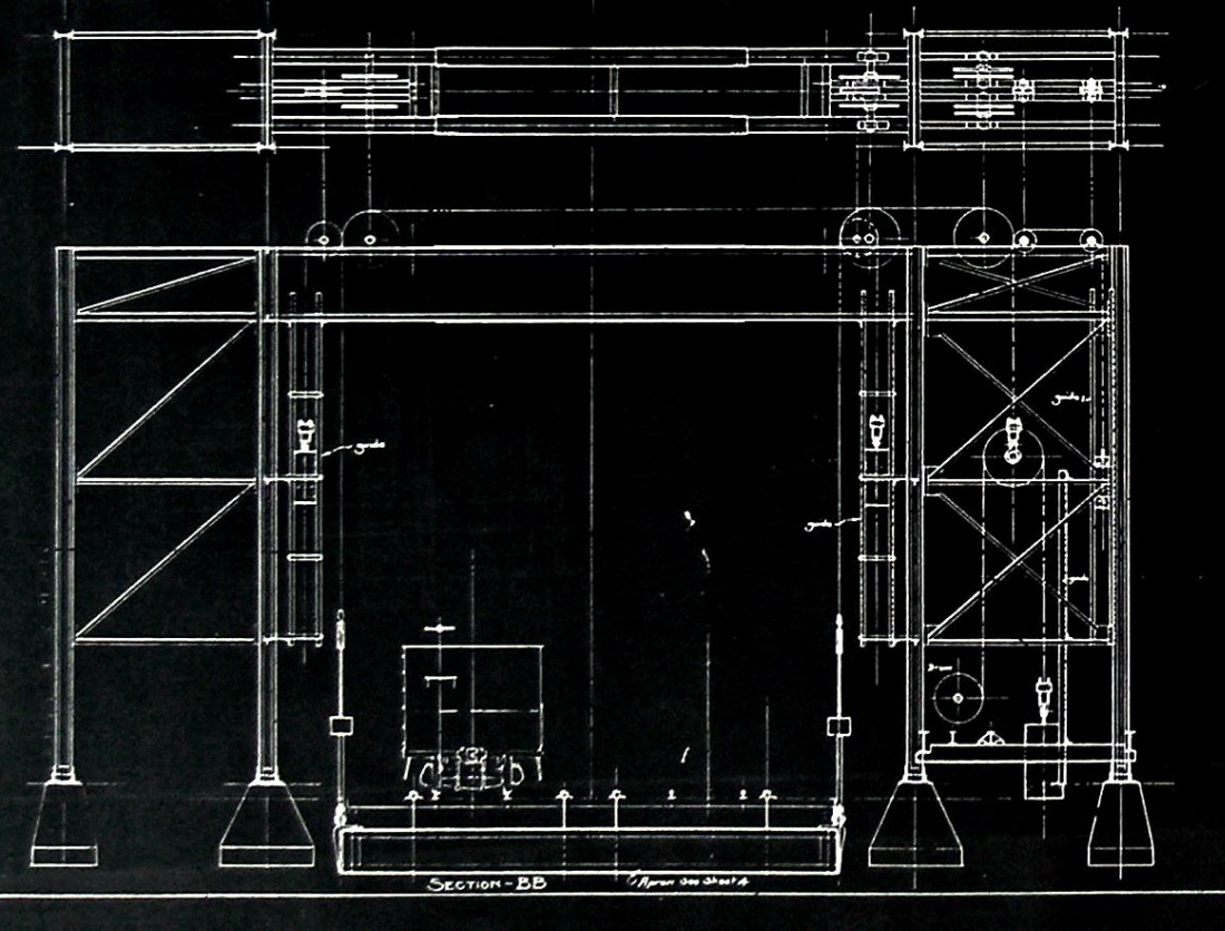
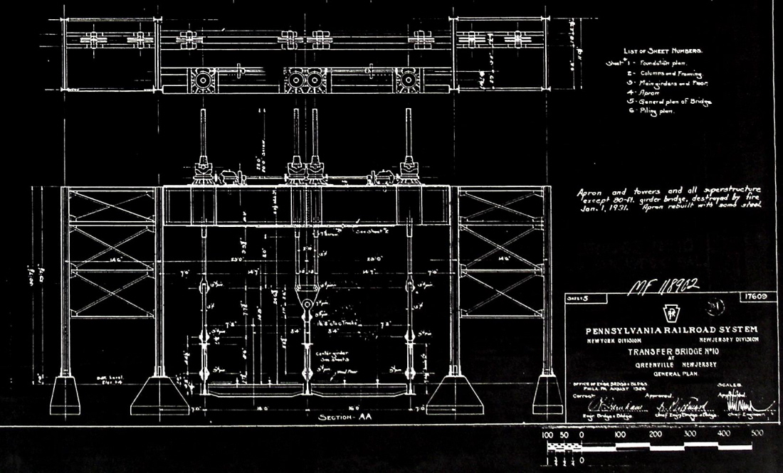
Pennsylvania Railroad - General Plan Transfer Bridge #10 - November
10, 1924
Pennsylvania Office of Engineering, Bridges and Buildings
T. Flagg / P. F. Strubeck archives
added 03 January 2012
.
.
At some point the original "transfer houses" (that enclosed
both gantries under one roof and in one structure) were modernized, greatly
changing the appearance of the transfer bridges and gantries. Despite the
fact that the wooden Howe Truss bridges were beginning to be replaced, it
obviously appears that the modernization really picked up in earnest after
the disastrous 1931 fire, that put all of the Greenville float bridges out
of service. As a result, it was decided to eliminate as much wood previously
used in the gantries. Siding and roofs would now be corrugated tin /
steel sheeting.
By 1946, there were six float bridges at Greenville, and all but two of them had been rebuilt.
By coincidence, this particular location was the last operation of original overhead suspended transfer bridges of any type left in the Port of New York. The automatic live load counterweight system was kept on Greenville float bridges #13 & 14, but unfortunately these bridges collapsed in 1991 and have subsequently been scrapped.
It should be noted at this time that two new overhead suspended float bridges were constructed in 1999 and located at Bay Ridge, but these appear to be of the West Coast style of overhead suspension cable lifted. One of these overhead suspended transfer bridges at 65th Street / Bay Ridge has been activated by New York New Jersey Rail, and the pontoon float bridge at Bush Terminal "Bush 2" 50th Street taken out of service July 2012. But it would be out of service for long. The Bush 2 pontoon float bridge as of 21 November 2012; has been relocated to Greenville, NJ as a result of the damage incurred and subsequent razing of the overhead suspended gantries at Greenville. This gives New York New Jersey Rail one operating float bridge on the west shore of New York Harbor, and keeps open the carfloating route to Long Island and points north.
Between 1901 to 1907, the New York Central Railroad would go on to build four separate apron transfer bridges, which were very similar to the original Greenville type built by the Pennsylvania Railroad, complete with a wooden Howe truss bridges; but these did not utilize the automatic live load counterweighting (Fig 10, 11) (Engineering News 1901; Electric Age, 1907). They used far more wood in their construction then steel for structural purposes: the pulleys were suspended from overhead wooden Howe trusses, which in turn were supported by a wood towers; in fact the wood Howe trusses of the bridges were further sheathed in wood with little gable roofs over each of them!
The transfer bridge at the foot of West 68th Street, Manhattan; was abandoned in 1968, and survived until 1980 before being set afire by vandals. Images reveal that its center truss is of a steel Warren truss design. It is unknown if this is original or a replacement, but otherwise the location has hardly been changed at all.
One was built at the West Shore Terminal at Weehawken in 1905. It appears to be in service as late as 1965.
Two transfer bridges were constructed at the foot of West 33rd Street (New York Central 30th Street Terminal) between Piers 72 & 73. The Port of New York Authority New York Harbor Terminals Map dated December 1940 show this location still marked for carfloat service. However, the 1943 edition of the map does not show carfloat service to this facility.
As mentioned above, the New York, New Haven and Hartford Railroad constructed eight float bridges of the most advanced overhead suspension separate apron type at their Oak Point facility located on the southeast shore of the Bronx, New York.
The Baltimore and Ohio Railroad constructed a single overhead suspended separate apron transfer bridge at their St. George, Staten Island facility in 1911, but this was removed circa 1942.
.
.
Considering that the Pennsylvania Railroad's Overhead Suspended Separate Apron Transfer Bridges that were constructed at Greenville, NJ were so historically important, not only from a standpoint in New York Harbor railroad history, but also of significant importance in regards to the fields of mechanical and civil engineering as well. As this website grows ever so technical and encompassing in its nature, it was felt by the authors that is was now appropriate to include the following.
In December 1996 and January 1997, the Greenville, NJ Transfer Bridges were photographed in great detail for the The Historic American Engineering Record (HAER). This HAER collection was established in 1969 by the National Park Service (NPS), the American Society of Civil Engineers (ASCE) and the Library of Congress (LOC) to document historic sites and structures related to engineering and industry. These images record many of the details overlooked or never seen by the casual observer.
And now, as these transfer bridges have been lost due to irreparable damage from the forces of mother nature in 2012, the importance of such a photographic program is even now more than ever greatly appreciated.
The 54 images contained within this collection are well exposed on medium format film (4" x 5") and show great detail. This collection also contains images of the collapsed gantries and spans of Bridges 13 and 14 just before they were completely demolished and removed as well as inside the operators cabin, a location rarely photographed. But perhaps best of all, these images are open access to to the public.
I have grouped the images together by Bridge (9½ Bridge, 10 Bridge, 11 Bridge, etc) and by interior shots, rather than in order of HAER numbering sequence. However, I have kept the HAER image number the same (seen on outside of the image frame) for ease of reference reference. Please note, while most of the data is correct in the original HAER image descriptions (available as a .pdf file attached to the group of images through the following link ), there were some minor errors. These have been noted in the descriptions below each image. The historian on record is Richard M. Casella, and the photographer is Rob Tucher.
You may wish to view the images here, but I have also provided a direct link to the uncompressed .tif images and associated research documentation for your convenience:
| Historic American
Engineering Record - NJ-49-A Greenville Yard, Transfer Bridge System - Port of New York / New Jersey; Upper New York Bay, Jersey City, Hudson County, NJ .
9½ Bridge
|
..
..
10 Bridge
(McClintic-Marsh - 1925)
|
|
| .
. |
|
|
| .
. |
|
|
| .
. |
|
|
| .
. |
|
|
| .
. |
|
|
| .
. |
|
|
| .
. |
|
|
..
..
11 Bridge
(American Bridge - 1945)
|
|
| .
. |
|
|
| .
. |
|
|
| .
. |
|
|
| .
. |
|
|
| .
. |
|
|
| .
. |
|
|
.
.
12 Bridge
(American Bridge - 1939)
|
|
| .
. |
|
|
| .
. |
|
|
|
.
. |
|
|
.
.
13 Bridge
(McClintic-Marsh - 1931)
|
|
| .
. |
|
|
| .
. |
|
|
| .
. |
|
|
| .
. |
|
|
| .
. |
|
|
.
.
14 Bridge
(McClintic-Marsh - 1939)
|
|
| .
. |
|
|
| .
. |
|
|
| .
. |
|
|
.
..
Interior Views
|
|
| .
. |
|
|
| .
. |
|
|
| .
. |
|
|
| .
. |
|
|
| .
. |
|
|
| .
. |
|
|
| .
. |
|
|
| .
. |
|
|
| .
. |
|
|
Gantry Footings (original cut block)
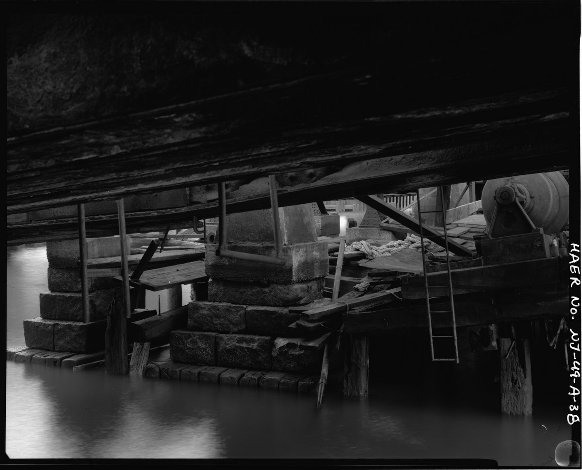
#38 - While not an interior image, this photo shows
the original gantry footings: cut granite blocks stacked pyramidically on
creosoted wood timbers.
Not surprisingly, these supports outlasted the steel reinforced concrete
footings, which fractured and spalled from water infiltration and subsequent
rust expansion of the steel rebar,
during thousands of freeze/thaw cycles.
added 14 February
2016
.
.
Greenville, NJ - Damage
to Demolition: 29 October through 17 November 2012
Unfortunately, as of 17 November 2012, the overhead suspended separate apron transfer bridges located at Greenville, NJ were razed due to severe damage inflicted upon them by Hurricane Sandy on 29 October 2012.
Decades of deferred maintenance (which is more often than not a euphemism for neglect) from all previous railroads (Pennsylvania, Penn Central, Conrail, Brooklyn Eastern District Terminal and New York Cross Harbor) took their toll. Throughout the years, 9½, 10 and 12 Bridges had been scavenged for parts, and left derelict to keep 11 Bridge operating. But despite their derelict state, they were all connected to one another via the gantries. Also, keep in mind when 13 Bridge & 14 Bridge collapsed and subsequently removed in the late 1990's, they too "tweaked" the connected overhead gantries. The overhead gantries of 11 Bridge, which was still in use by NYNJ Rail at the time Hurricane Sandy, has compromised by decades of underscoring of the neighboring underwater foundations, supports and columns; salt water corrosion on the entire structure as well as general wear & tear.
When Hurricane Sandy came ashore pushing her storm surge and winds driving a work barge against and ultimately into the structure became the final straw. The Port Authority of New York & New Jersey (PANYNJ and the parental agency for NYNJ Rail) commissioned site and structure feasibility surveys. In the end, the cost of repair was not worthy of investment.
The following images were furnished by Paul Strubeck, who transited through New York Harbor in person and aboard a tugboat on November 2, 2012, just four days after Hurricane Sandy:
|
|
| .
. |
|
|
| .
. |
|
|
| .
. |
|
|
| .
. |
|
|
| .
. |
|
|
| .
. |
|
|
| .
. |
|
|
| .
. |
|
|
| .
. |
|
|
| .
. |
|
|
.
.
The following set of images, taken on 17 November 2012 of the
demolition; were furnished by Giancarlo Schiano and Kevin Ciampi. These gentlemen
are professional engineers and were directly involved in the aforementioned
site and structure feasibility surveys, as well as the the
relocation of the Bush Terminal 51st Street "Bush
2" float bridge (to replace the Greenville transfer bridges); and proposed
transfer bridge to be built:
Overhead Suspended Hydraulic Span
Hydraulic Apron.
|
|
| .
. |
|
|
| .
. |
|
|
| .
. |
|
|
.
.
So, with the demolition of the Greenville, NJ transfer bridges, no overhead suspended separate apron transfer bridges survive in New York Harbor.
.
.
wood Howe Truss (enclosed)
The earliest designs of the separate apron span were of wood Howe Truss design similar to the design of pontoon Howe Trusses. However, these trusses would be encased in wood siding, with miniature peaked roofs on the top of each span. The reason for this sheathing is not determined, but logic would have it to protect the wood trusses from weather. As this design was used almost exclusively at the large all enclosed gantry houses of the early separate apron, it might have also cut down on the amount of wind blowing through the gantry house.
.
steel Through Plate Girder
The next step in span design evolution, was the steel riveted through truss span. Again, these looked just like their counterpart in pontoon type, but were slightly longer. In this application, three girder type were popular.
.
wood Howe Truss (outside) with Steel Pony Truss (center)
There was one known hybrid span type, and it was a composite of both construction material: wood and steel, and of truss design: Howe (wood) and Warren (steel). In this design, the outer trusses were conventional wood Howe design, but the center truss what steel lattice truss beams in the Warren configuration. Another unusual feature of this span, was that the inshore ends of the Howe Trusses were squared as we have come to see and expect on other Howe Trusses; however the outshore end simply ended with the last diagonal brace.
This bridge was part of the former New York Central Railroad 60th Street Terminal, and is located at the foot of West 67th Street, in Manhattan. This span was the main span of a overhead suspended separate apron.
It has not yet been determined at this time, if this float bridge was initially constructed like this or whether it was modified from a conventional three wood Howe truss, and at some point of it history the center truss needed to be replaced and was replaced with steel. This bridge span survives, but unfortunately it is a semi-burnt state which completely destroyed the gantry house and left the span partially submerged. We are unsure of the apron's design, or even whether or not it has even survived, so it has been omitted from the illustration. below.
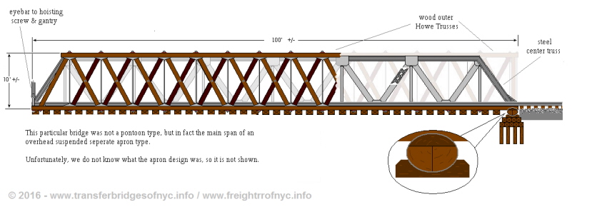
not to scale
Where were these freight cars going?
The Greenville float bridges were built primarily to handle the Pennsylvania Railroad's interchange with the New York, New Haven and Hartford Railroad (Railway Gazette, 1905). Starting with three float bridges in 1903, by 1920 there were four float bridges at this location, and by 1931 there were five. During World War II, a sixth transfer bridge was added. A large proportion of the non-coal traffic between New England and the South and West passed over these float bridges.
In 1928, the PRR - NYNH&H / LIRR interchange was averaging 1600 cars per day, and changes were jointly agreed upon to increase the efficiency of these operations. The schedule provided for nine round trips per tugboat per day, with a normal equipment assignment of two tugs and four pairs (total eight) of carfloats. The old and new arrangements were described in an article (Railway Age, 1931) that gives a fascinating insight into the Port of New York carfloating operations, including: schedules, classifications and preparations for emergencies. During World War II the volume of traffic passing through these float bridges was tremendous, and probably exceeded that of any other set of floating bridges operating anywhere else in the United States. At its peak, freight traffic on the Greenville - Bay Ridge route was 2160 cars per day, which breaks down to 90 cars per hour, day and night (Rohde, 21). Even as late as 1964, shortly before the ill-fated Penn Central merger put an end to all New England interchange through the Port of New York, an average of 400 cars per day transited through the Greenville float bridges (Tri-State, 1967).
A visit by Rail Marine Information Group members to the Greenville float bridges in September 1994, turned up a pile of paperwork from 1961 - 1965 connected with the interchange of cars at this location. As at any railroad interchange point, a record was made of each freight car passing through. PRR Form 2022 was used at this location in 1961; this form comprised of one original with seven carbon copies per page and listed all the cars on each carfloat that was loaded or received! It should be noted that eastbound cars were almost all loaded and included a good deal of produce and other foodstuffs. Some of the westbound carfloats carried mainly loads, while others seemed to consist of mostly empty cars being returned to their owners (New England terminated fewer cars than it originated).
At this point in the original publication, credit is given to RMIG member Tom Lane of Karl Koch Erecting, Co.; Carteret, NJ; who rendered great assistance in obtaining the original copies of the plans show in the Transfer article. Those that have not since been located in digital archives remain from the original printed publications..
.
..
Installation Locations:
Tracking the Separate Apron Transfer Bridges
Unfortunately, due to the wood construction used in the early era (pre-1900's) in construction of both the bridge span and/or the gantry-house, almost all of the early overhead suspension separate apron transfer bridges did not survive, whether be it due to modernization to steel construction or fire. The only survivor to date is the charred remains of the West 69th Street Howe Truss bridge (span only) in Manhattan. Even in its current unrestored and derelict state, it is the only remaining example of an Overhead Suspended Separate Apron wood Howe Truss bridge. The apron cannot be seen, and so it is unknown whether the apron is below the water, or was burnt by vandals in the gantry-house fire.
And as of October 2012, all of the Greenville Transfer Bridges have been demolished.
.
Pennsylvania
The Pennsylvania Railroad from historical accountings, had upwards of about twelve of this type of transfer bridge in service:
six at Greenville, NJ;
one on Manhattan at their West 37th Street Freight Station, and
five (possibly more) at Harsimus Cove (all out of service about 1968 and all were demolished by 1980).
.
New York Central
The New York Central constructed several overhead gantry separate apron transfer bridges at various facilities in New York Harbor:
four at West 69th Street, Manhattan;
one at the West Shore Terminal at Weehawken, New Jersey;
two at the 30th Street Terminal in Manhattan (at the
foot of West 33rd Street between Piers 72 & 73.)
.
.
|
|
| .
. |
|
|
| .
. |
|
|
.
.
New York, New Haven & Hartford
The New York, New Haven and Hartford Railroad constructed eight float bridges at their Oak Point Facility in the Bronx, from 1910 through 1911; with room for four more had freight traffic warranted. These replaced four pontoon bridges at that location.
.
Baltimore & Ohio
The Baltimore and Ohio Railroad constructed several (exact number unknown, believed to be four) at their St. George, Staten Island facility in 1911. All but one would be removed by circa 1942.
.
.
..
Overhead Suspended Swiveling
Head Block: A. H. Mallery's "Swiveling Head
Block"
.
| One Failure = One Success | James B. French to the Rescue | Tracking the Mallery Types | A. H. Mallery mini-bio |
.
..
Only the richest railroads could afford the Greenville overhead suspended separate apron type transfer bridge. In an effort to create a transfer bridge that retained some of the virtues of the suspended bridge but without its high cost, Arlington Humphrey Mallery, an engineer for the Long Island Rail Road, designed and patented a new suspended bridge (US Patent #743,901; November 10, 1903:
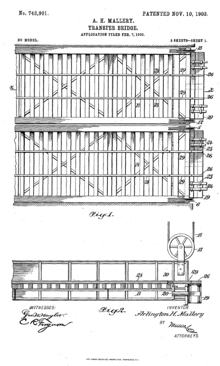
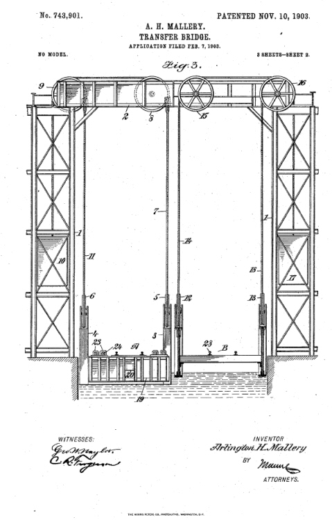
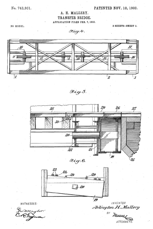
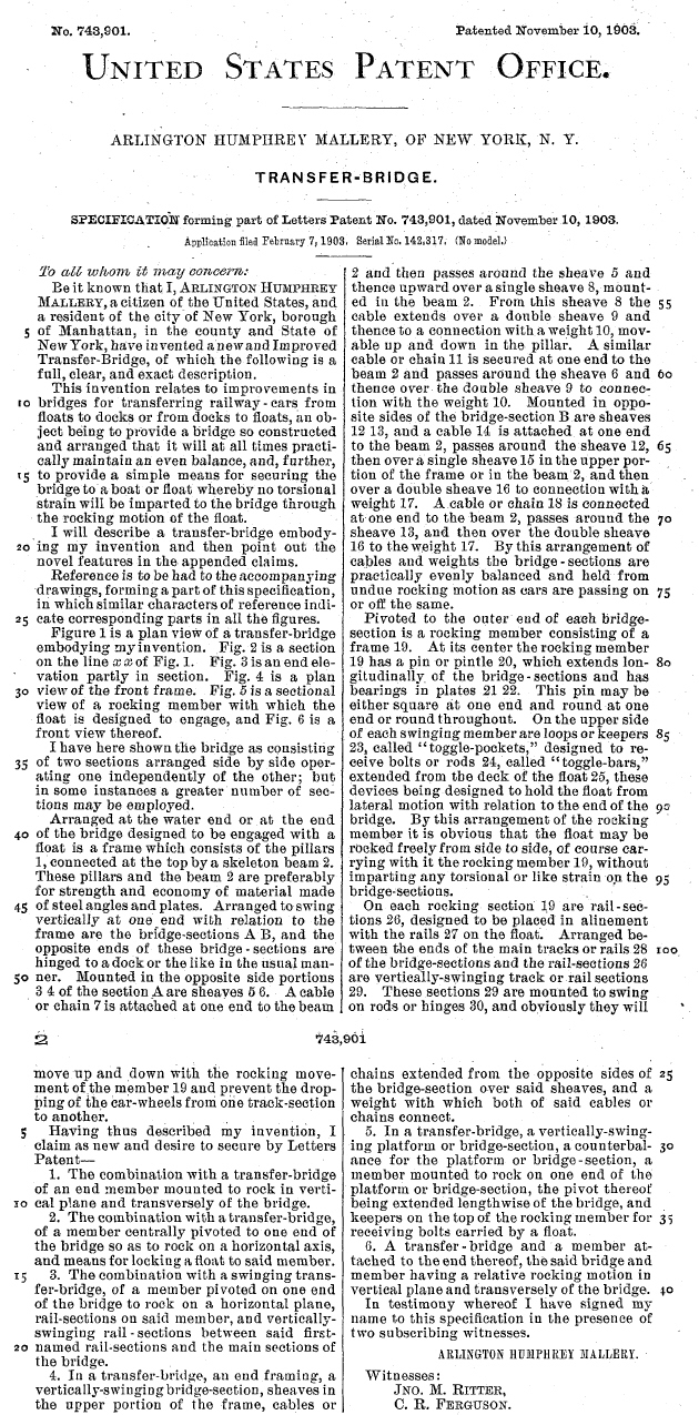
via Google Patent
Search
added 30 December 2011
.
In 1904, two transfer bridges of the Mallery design were constructed at the Long Island City Terminal of the Long Island Rail Road. With a primary emphasis on economy, Mallery avoided the cost of the apron suspension system by eliminating the apron altogether, employing instead two innovations to incorporate the needed flexibility.
First, he replaced the standard single two track bridge with two independently suspended bridge span of one track each, mounted side by side and of one track each. These were hung from a common overhead framework. This allowed one track to be raised higher or lower than the other, and thereby taking up some of the torsional stress. There was just enough clearance between tracks on the standard carfloat to allow four complete sets of girder and suspensions (French, 1917, 65). This ingenious invention was not claimed in the patent perhaps be cause itself it was not an Patentable idea.
Secondly, Mallery substituted for the regular apron a "swiveling head block", which was simply a 2 foot deep spacer block at the outer end of each bridge span. These would pivot at its center on a 10 inch cantilevered pin going into the middle of the beam under the track ends. In effect, this was a rocking transverse girder. This swiveling head block design carried the outer ends of the rails where each rail was hinged independently for up and down motion. This was designed to flex as the block swiveled.
As Mallery relied on the use of separate bridges for each track to take up the overall twisting and these blocks would only need to take up the twisting within the track gauge itself. The swiveling head block was essentially the only new feature claimed in his patent. The design was ingenious, but in the kind of rough service that these float bridges perform, puts a great deal of stress on every connection, and a swivel pin supported at only one end cannot take such a stress. In addition, the swiveling head block was too short to serve the various functions of an apron; in particular it did little to ease the vertical angle between freight cars going on to the carfloat.
One other change made to save on costs was the elimination of the rigid system of screw rods and eyebars that lifted the main spans (as incorporated into the design of the separate apron in the Part II above). Mallery employed the usual counterweights to balance most of the dead weight, but the actual lifting and lowering of the new transfer bridge was done by differential chain pulley blocks, operated by hand no less. Presumably this lifting apparatus was used only to adjust an empty bridge to the height of an incoming carfloat, much as pontoon type bridges of the time were adjusted as we read in Part I.
After the carfloat was attached to the bridge by way of the swiveling head block; the dead weight in excess of the counterweight, plus all the live load, was transferred via the toggles to the carfloat. Thus the weight put onto the carfloat was probably in excess of any previous transfer bridge design whether it be pontoon or suspended type (French, 1917, 66). In addition the supporting structure for the counterweight system was not strong enough, as would shortly be made evident.
The design of these transfer bridges caused the end of the carfloat to sink more than usual while being loaded, but apparently this greater submergence was not taken into consideration when deciding how high to make the towers that supported the counterweights. As it turns out, the original design as constructed, allowed 90% of the dead load to be taken by the counterweights, with the remaining 10% taken up by the buoyancy of the carfloat.
One day, not long after these transfer bridges were put into operation, the combination of a low tide and a heavily loaded carfloat caused the counterweights to go to their highest position at the top of the towers and strike an obstruction (the gantry perhaps? PMG). When the loaded freight cars were finally upon the bridge structure itself, all combined weight: the "live" weight (the freight cars and carfloat) and the "dead" weight (the float bridge) of which was now unbalanced and no longer being counterbalanced by the counterweights, transferred this load to the weakest link in the suspension mechanism, which was the sheaves and sheave axles carrying the counterweight cables.
This resulting stress caused the sheave or sheave axle to give way, releasing all the combined weight and causing the bridge span to drop into the water, freight cars and all! Simultaneously, the counterweights which were at the highest point possible at the top of the towers and now relieved of any and all load, free fell the thirty or so feet from the top of the towers to, and through, the timber tower foundations and thereby destroying them in the process.
What might have been a routine day, must have turned into mayhem in a very short span of time! And as it turns out, a similar but less serious accident of similarity had preceded this one, taking place on the other transfer bridge (French, 1917, 65 - 67; Engineering News, 1911).
.
James Benton French to the
rescue
After this debacle at Long Island City, another engineer employed by the Long Island Rail Road by the name of James Benton French was brought in to correct things. And correct things he would.
Since the transfer bridge was urgently needed, he did what was requested of him: the minimum. In 1905 he repaired the transfer bridge using the Mallery's design, but raised the counterweight towers to allow for more travel of the counterweight. In addition, to handle the live load and also to allow efficient raising and lowering of the bridge, he added screw supports raised by rotating nuts in the overhead structure, such as those in the system employed at other overhead suspended separate apron type transfer bridges.
He also strengthened the pivot points of the head blocks and made other improvements. The same changes were made to the other transfer bridge in 1906. But still other problems surfaced, including the frequent breaking of the 10 inch cantilever pins; so French added further support for these pins at their outer ends.
While these modifications as explained above may have solved the situation, they were nothing short of expedient. More problems arose and yet another French modification was needed: and a slip joint added to the threaded rod assemblies to allow sudden upwards thrust motion to occur without damaging the threaded screw assemblies.
Prior to these modifications, the slowness of the bridging at Long Island City had been a source of humor at meetings held by the Railroad Club of New York of that time.
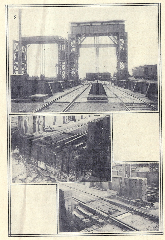
The Development of Carfloat Transfer Bridges in New
York Harbor, J. B. French - 1917
Plate III
| 5: Shows one of the original Mallery (left)
and the French modified (right) bridges. 6: The swiveling head block (without carfloat) 7: The compromise rails and carfloat attachment (with carfloat). |
P. M. Goldstein
collection
added 02 January 2012
As we will see, it would be the failure of the original Mallery design that would lead to an engineering marvel. It was while making these repairs and additions to these transfer bridges, that French devised a new way of building a transfer bridge that, like Mallery's design, did not require a separate support system for the apron, but unlike the Mallery design, French's design would have all the advantages of a full working apron. Any good engineer will learn to recognize the short comings of an existing design and formulate a solution, and we shall read about this in the next chapter.
.
Tracking the Swiveling
Head Block / Mallery Type Transfer Bridges
As a result, the Swivelling Head Block or Mallery type was not an overly popular design and did not meet with widespread use within New York Harbor. There were only two known Mallery types constructed in New York Harbor.
two at Long Island City, Queens (Long Island Rail Road)
.
The 1992 book "Bridges & Trestle Handbook" which was written by Paul Mallery (son of A. H. Mallery), presents bridge design ideas for the model railroader. This book contained a very brief description of this suspended type transfer bridge. However, it omitted the above Long Island City incident, and left out other pertinent information applicable to the prototype. It also appears to attribute all the credit of Bensel's and French's innovations to his father. (see table of references).
Mr. Mallery in future correspondence has made it a point to state he was unaware of the error and said he was just re-iterating what his father had told him in the past.
.
|
|
Arlington Humphery Mallery was born in Syracuse, New York on January
3, 1877
He served as a cartographer and held the rank of Captain in the United States Navy during the Spanish-American War in 1898. Other than being civil engineer; he would also incorporate and become president of the Syracuse Bridge Company in 1904. In 1916, Arlington was a one-time Democratic Party candidate for Representative of Congress of the 35th District (Onondaga & Cortland Counties) of New York. |
| The following year, Arlington H. Mallery married
Marta Paula Wittkowska, a Polish–American contralto opera singer, who
would perform in many well respected opera houses of several large cities,
including "the Met" in New York City.
In 1951, Mallery would go on to publish "Lost America - The Story of Iron-age Civilization Prior to Columbus". In his book, A. H. Mallery explains it was while working with his father, was where he gained his first experience with metallurgy, forging and tempering tools such as drills, chisels, axes and adzes. Mallery went on to state he laid many a stone in his father's bridge foundations and even helped erect the steel framework. Mallery was also an accomplished archeologist and cartographer, even having the opportunity in 1956 to study and one of the first to speculate on the possible pre-Columbian origins of the 1513 world map created by Haci Ahmed Muhiddin Piri also known as Piri Re'is, better known as the "Piri Reis Map". He also postulated in a thesis that Nordic Vikings discovered North America 500 years before Christopher Columbus. Arlington. H. Mallery passed away on August 4, 1968. His son Paul was involved with modelling bridges for model railroading, but unfortunately Paul passed away in 2004.
|
|
.
.
Overhead Suspended Contained
Apron: James Benton French
.
| A New Design | The Contained Apron | Light & Heavy Duty Versions |
| The Successful Design meets with Widespread Acceptance | James B. French mini-bio | Installations: Tracking the Contained Aprons |
.
..
A New Design Gains Immediate
Dominance
First built in 1911; this contained apron transfer bridge is still standing to this day! And as a testament to it's ingenuity and success, most of the bridges that people think of as the "classic New York design", with an overhead "gantry" are the contained apron type, including the Long Island Rail Road's float bridges at Long Island City. Only the Pennsylvania Railroad stayed with the "separate apron" design after 1911. French would patent his design in 1911 (Engineering News, 1911, 770; French, 1917; French, U. S. Patent #983,617, Feb 7, 1911):
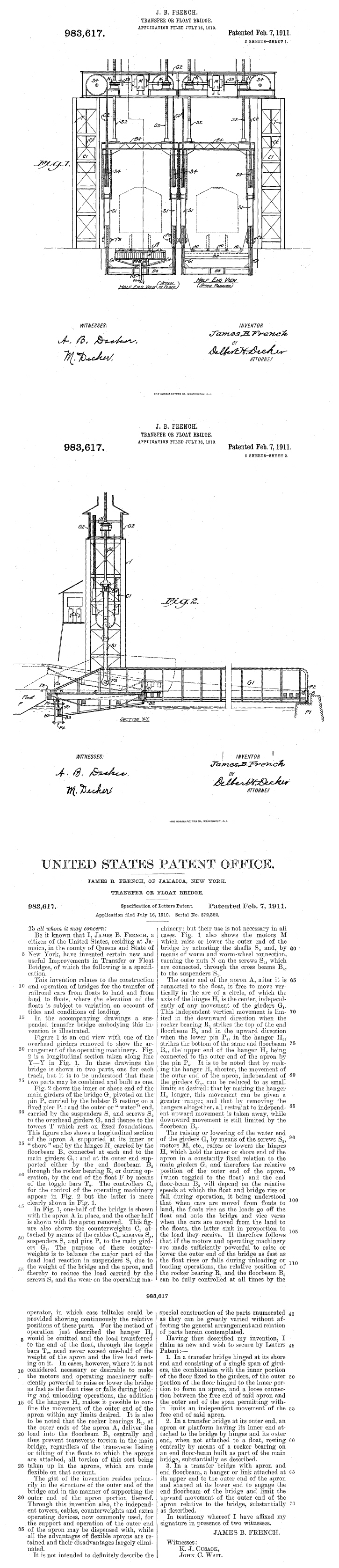
via Google Patent
Search
added 30 December 2011
.
.
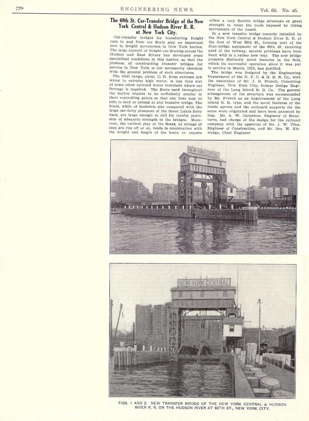
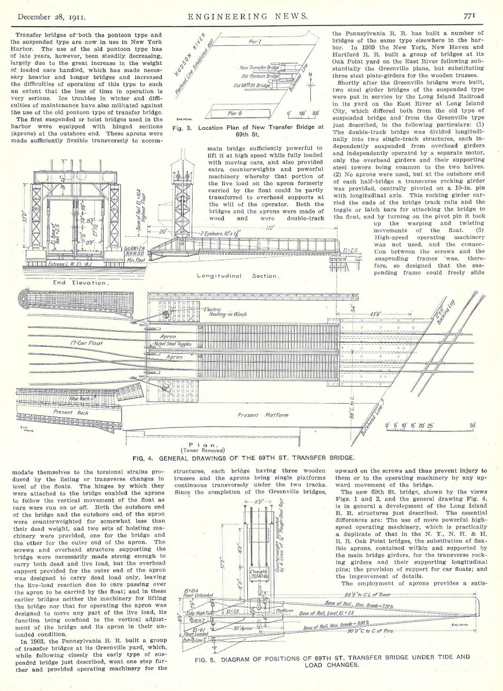
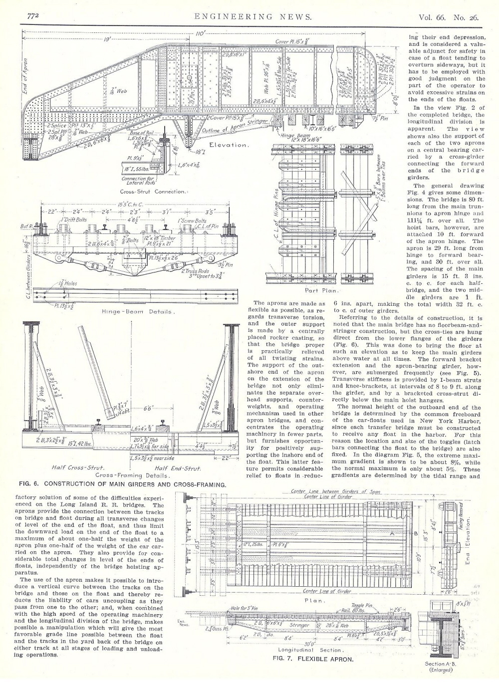
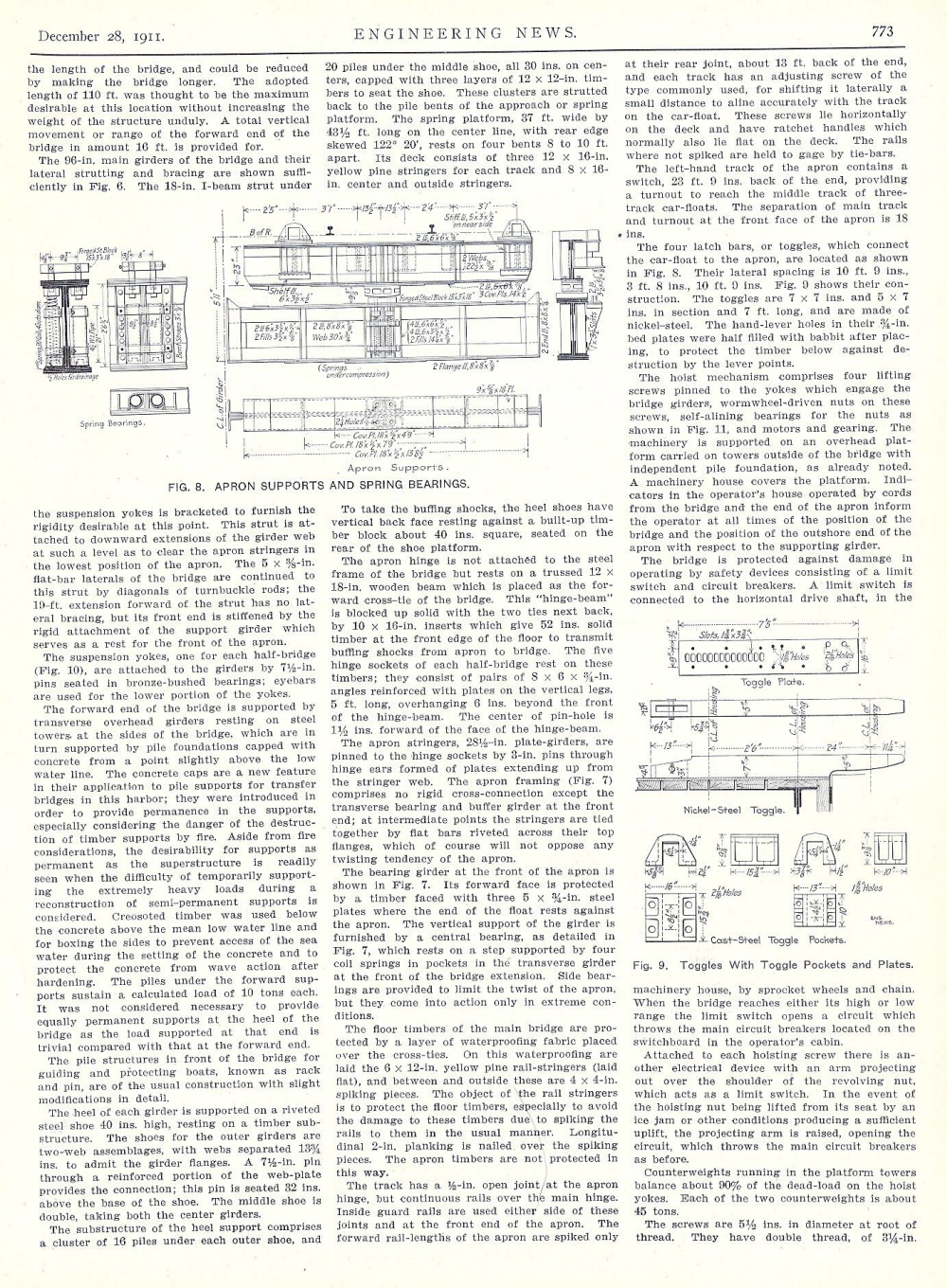
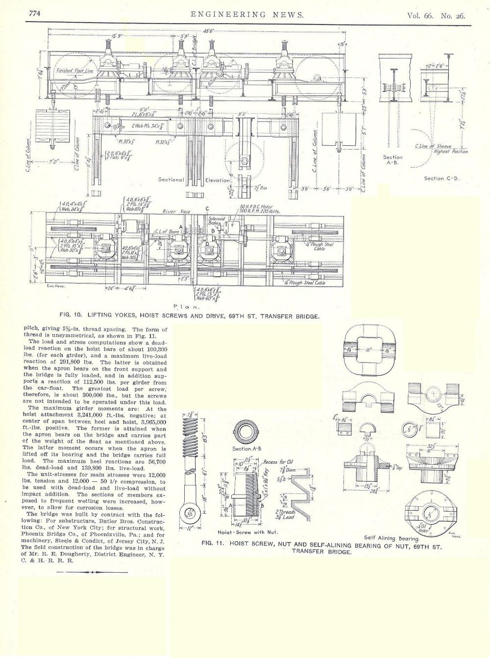
Engineering News - Volume 66, No. 26 - December 28,
1911
authors collection
Please note: high resolution scans of the construction drawings are available
upon request)
added 29 April 2012
.
In his design, French kept Mallery's basic idea of using a separately suspended main span for each track, counterweighted to balance most of the dead load. However, French deviated from Mallery's design, by suspending each bridge span from its own cross beam or "yoke" above it. The counterweights for the dead load were located in the support towers. They are attached to these yokes and sheaves (by way of the counterweighting cables) and one set of counterweights is visible just above the far yoke.
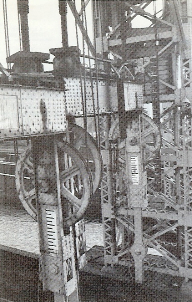
Long Island Rail Road - Long Island City - January
1972
Individual span yokes with height gauge markings.
Far span is slighter higher than near span.
T. Flagg photo
added 04 January 2012
.
Each of these yokes in turn were raised by their own pair of hoisting screws (a pair for each yoke) and driven by gimballed power nuts, one for each hoist screw extending up into the overhead structure. Each pair of power nuts were powered by a common shaft with worm gears to ensure they would turn at same rate:
|
|
|
|
|
|
.
To isolate the twisting motions of the carfloat from the relatively rigid suspended span, he replaced the "swivelling head block" with a new type of apron. French called it a "contained apron" because it was contained with in the main span, rather then suspended beyond its outer end, as with the overhead suspended separate apron type transfer bridges described in that chapter of this website.
The side girders of each span were extended outward far enough to enclose a 30 foot apron set between them. This apron's outer end rested loosely on a "rocker" placed on the transverse beam held between the outer ends of the girders. This allowed the apron's outer end to twist from side to side, yet gave support to both dead and live loads on the apron and by this effect, the rocker transferred the load to the main span.
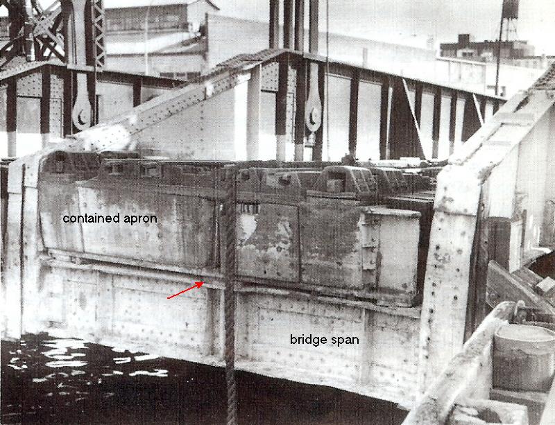
Long Island Rail Road - Long Island City - March 1977
Showing the outshore end of contained apron and span. The rocker casting
is missing and would be located directly behind rope at arrow.
(Ignore dangling rope.)
T. Flagg photo
added 04 January 2012
.
The inner end of the apron was hinged to another transverse girder framed between the sides. Because the outshore end of the apron simply rested on the rocker casting, it was free to move upward with the carfloat, e.g.: when a load was removed from the carfloat. The apron's floor structure allowed its deck to twist without incurring damage, and without transmitting torsional stress to the hinge.
This design, according to French (1917, 69), secured all the advantages of the Greenville type of overhead suspension separate apron transfer bridge, but with simpler construction and significantly less machinery, since it eliminated the need for a separate support system for the outshore end of the apron, and so doing away with the live load counterweight system and its supporting framework, as well as also simplifying the bridge operators control of the span.
.
.
To prospective parties, they could save still even more money (according to French), for under conditions of light freight traffic, the apron could be constructed shorter (and its upward movement therefore necessarily more restricted), and slower hoisting machinery substituted.
In 1909, French showed his floating bridge design to engineers of the New York Central Railroad, who were about to construct a brand new transfer bridge at the foot of West 69th Street on Manhattan which was at the north end of their West 60th Street Freight Yards. After having considered the various alternatives, the New York Central railroad built their new transfer bridge to French's design.
Specifically, they used a "heavy traffic" version of the design, with main spans 110 foot long over all, containing within each a 30 foot apron, and with four hoisting screws each 7 5/8 inches in diameter. The main cables were 1 ¼ inches in diameter. Two 50 horsepower direct current motors were provided, making the bridge capable of lifting a full load of 50 ton freight cars. This transfer bridge entered service in March, 1911. Figures 4 through 11 as represented below have been reproduced from Engineering News, 1911; which should give our modelers sufficient detail to construct this design with complete fidelity.
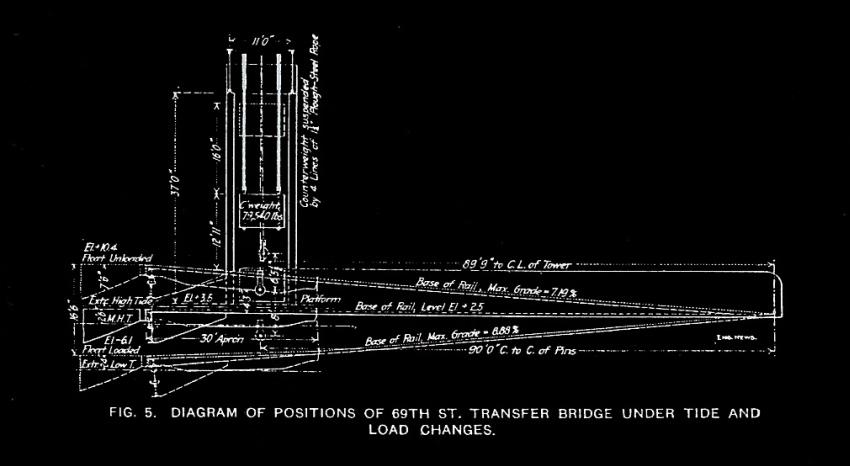
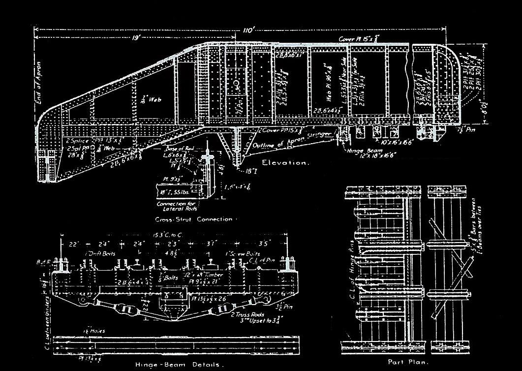
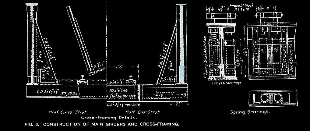
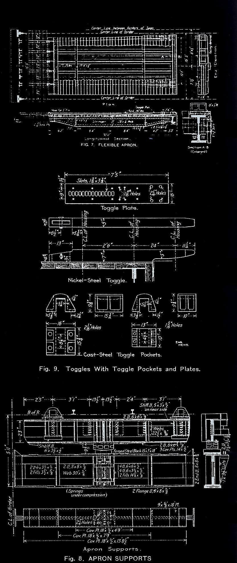
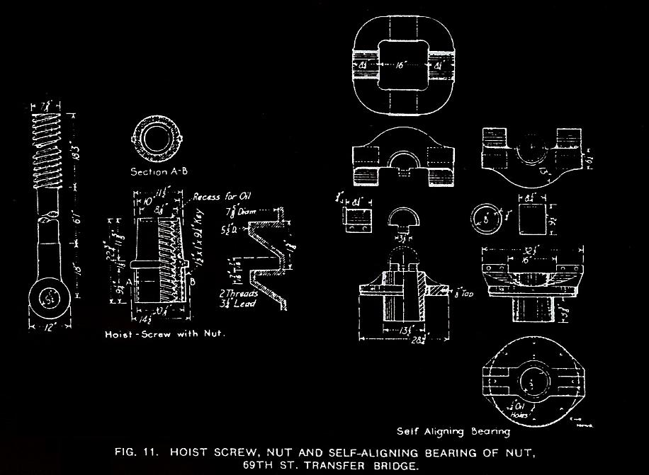
Each of the two single track main spans weigh 78 ½ tons, yielding a dead load of 100,300 pounds at the outer ends, with 90% of this carried by the counterweight. The load at the heel or inshore end was 56,700 pounds. The maximum live load reaction was to be 291,800 pounds on each side, with the bridge fully loaded and the carfloat bearing down on the end to the extent of 112,500 pounds on each side. This maximum load would apply a 150 ton force to each screw, though the screws were not expected to lift the bridge under this much load (Engineering News, 1911, 774).
The rails on the main spans were supported in interesting if unusual way: instead of using floor beam and stringer construction, the girders were connected by long wooden ties suspended from their bottoms and on these were laid longitudinal beams, and the rails were laid upon these (shown in Fig. 6). In addition, there were I-beams tying together the main girders.
The bridge footings were built by Butler Brothers.; the steel structural work by Phoenix Bridge Co. of Phoenixville, PA; Steele and Condict of Jersey City provided the machinery (as they did for nearly all of the later transfer bridges of this type). R. E. Dougherty, district engineer of the New York Central Railroad, was in charge of field construction work.
It appears, but is not confirmed conclusively; that French's rebuild of the failed Mallery Type at Long Island City may have been of the "light" duty French design.
.
The Successful Design
meets with Widespread Acceptance
French claimed the bridge was very successful, being both more economical and easier to operate than previous suspension types, while at least matching them in strength and speed. His claim is supported by the choice of his design for the four bridges constructed in 1916 at the new Long Island Rail Road / New York New Haven & Hartford jointly operated Bay Ridge / 65th Street Terminal in Brooklyn. The Long Island Rail Road and New York, New Haven & Hartford Railroad would jointly operate this terminal for the intent of cutting short the long carfloating route between Jersey City and the south Bronx for Pennsylvania Railroad traffic (other railroads would continue to deliver to Oak Point).
In the overhead suspension separate apron chapter of this website, we described the New York, New Haven & Hartford's Oak Point transfer bridges as constructed in 1908, as the most advanced version yet of the Greenville overhead suspended separate apron type transfer bridge.
But the Bay Ridge transfer bridges were even more important as they were to receive the freight cars sent from the Pennsylvania Railroad's Greenville transfer bridges, so those card could be forwarded to New England via the newly completed Hell Gate Bridge (1917). Thus these new transfer bridge were a vital link in the freight portion of the Northeast Corridor. Given the Pennsy's influence in this whole project, and the success of the Oak Point transfer bridges, the choice of French's overhead suspended contained apron type for the Bay Ridge transfer bridges is very strong testimony for French's new design.
The LIRR / NYNH&H Bay Ridge transfer bridges were constructed to an even heavier design than that used at the New York Central's West 69th Street transfer bridge built in 1911. While the Bay Ridge spans were also 110 feet in length, the electric motors used at this location were two (per bridge) 75 horsepower alternating current type. Also, here the rails were supported on the usual system of steel stringers and floor beams.
Ultimately, these bridges were capable of carrying on each track, a heavy steam locomotive with tender followed by a train of 70 ton coal hoppers, and capable of lifting the bridges when thus loaded at the speed of 5 feet per minute, measured at the bridge end! (French, 1917, 73)
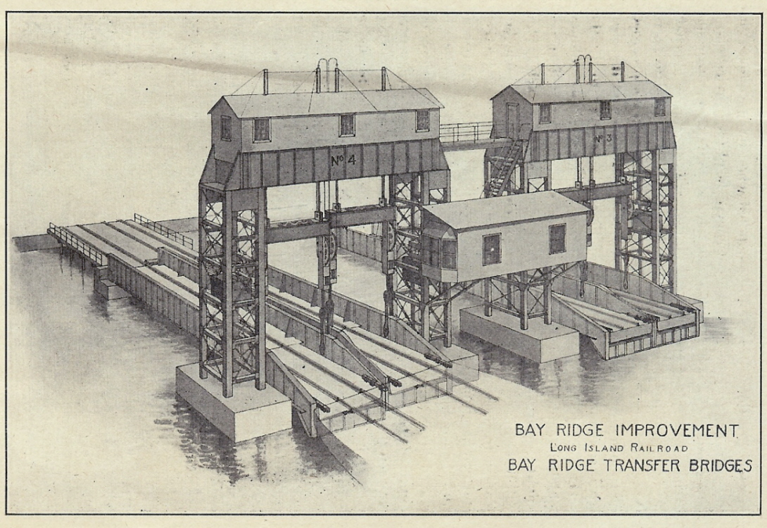
The Development of Carfloat Transfer Bridges in New
York Harbor, J. B. French - 1917
Plate VI
P. M. Goldstein
collection
added 02 January 2012
The four float bridges constructed at Bay Ridge were divided into two pairs: each pair was operated by a crew of three men: one bridge operator who handled the electric controllers located in the cabin of which was mounted between the two sets, and two bridgemen did the manual work (winching, toggling switch throwing, track aligning, etc.) at track level. A single maintenance man looked after the lubrication and general maintenance of all the bridges; in particular it was necessary to keep the hoisting nuts and screws well lubricated with a combination of grease and oil, in a manner depending on the weather.
French reported that it took about 3 to 4 minutes to make the connections between the transfer bridge and carfloat, after the latter had been warped [sic] into the slip. Under favorable conditions a loaded carfloat could be bridged, unloaded, reloaded and released in less than 30 minutes. This was normally much faster than the freight cars could be switched in the adjoining railyard, and /or carfloats handled or positioned in the water at that time (French, 1918, 94-95).
Space was set aside to build an additional two transfer bridges at a later date (French, 1917, 71), but this was never found necessary, even though at Greenville six transfer bridges were found necessary during the heady days World War II! By that time, both freight car handling and carfloat handling were made efficient enough to match the bridging time. As we read before; under the extreme pressure of World War II freight traffic, each set of bridges handled an average of 90 freight cars per hour continuously, 24 hours a day, seven days a week!
A fine color picture of one of these transfer bridges appears in Kalis, 1993, p. 56 (although mislabeled as a Long Island City transfer bridge). It shows the New York New Haven & Hartford Railroads 11,000 volt AC catenary extending right out to the yokes that suspended the outer ends of the bridges. It also clearly shows the longitudinal planking on the bridge decks, for the benefit of the bridgemen.
This contained apron design was so successful, that after 1911, every new suspension type transfer bridge was built to this contained apron design, with the exception being for those separate apron types already having been constructed by the Pennsylvania Railroad (which stayed with their Greenville design), and in those locations where the PRR was either rebuilding, or adding to, sets of already existing separate apron transfer bridges.
French also revised the design of the threaded hoisting rod and rotating nut assembly. Figure 1 is top view, Figure 2 is side elevation view. Keep in mind there were two of these per span:
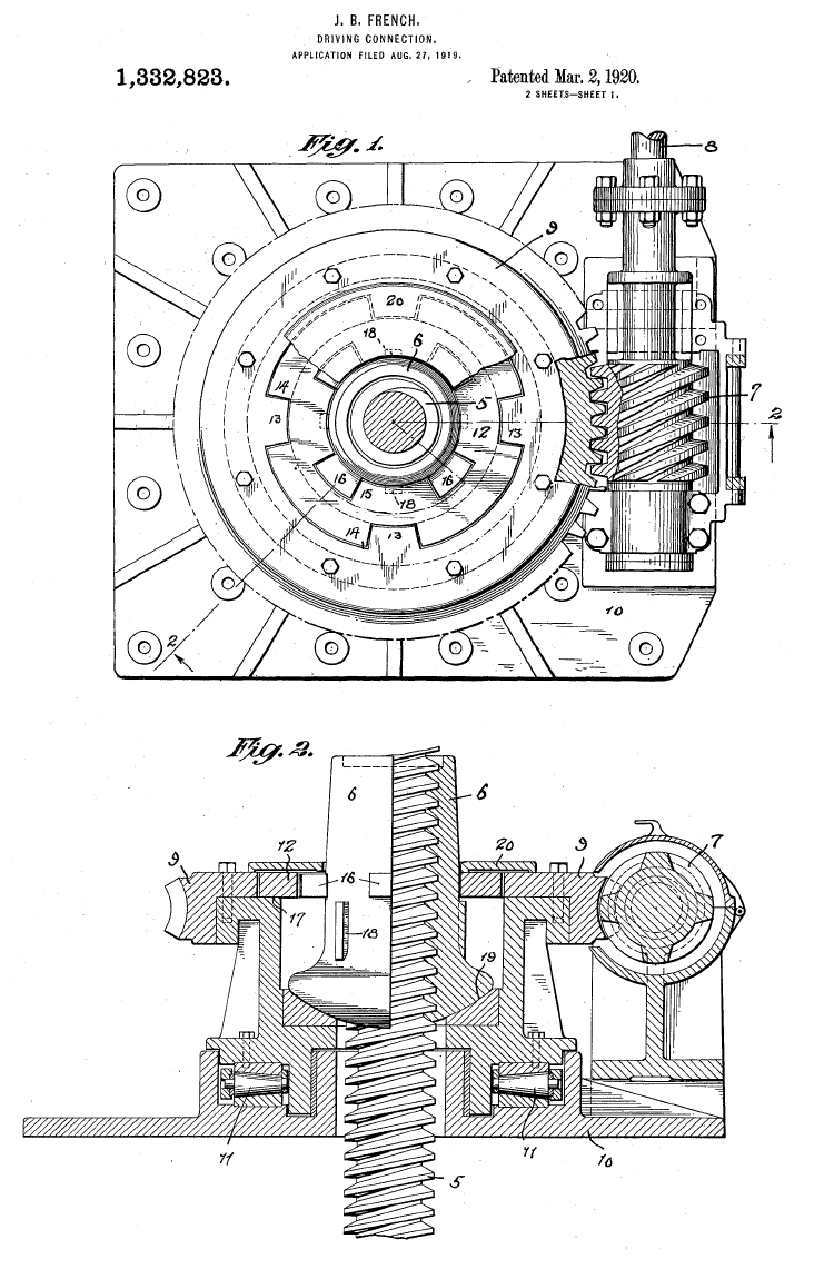
via Google Patent
Search
added 30 December 2011
.
This however, is not to say that the Pennsylvania Railroad did not keep an open frame of mind, and in 1929 at Jersey City it chose to construct a pair of French's contained apron transfer bridges when new transfer bridges were needed at this location.
Long Island Railroad - Long Island City Transfer Bridge 5 collapse in 1970 - so what happened?
"It was still daylight when we had coupled up to the first car on the float. I then swung down off the float flat (reacher car) to get between the flat and the first car and bent down to hang the (air) hose when I heard this loud noise. I jumped up and looked around and saw the engine starting to tilt and the float under my feet start to move.
I didn't know that I could move so fast but when it all settled down, I was safely out of the way.
When the new Trainmaster on duty came to the scene, he asked me, "How fast were you going?" This was the standard question asked at all mishaps,
found on page one of the New Trainmaster's Handbook.
"We were standin' still" was my reply. "Aww! Bullshit" came the bellow of the Trainmaster.
Words got a little testy until everyone understood that this was the boss.
To make a long story short, no one was injured, no one was disciplined, #5 Bridge was put out of service and Alco S1 #421 was cut up for scrap ( there were new engines on order anyhow.)
It wasn't long afterward that all floating operations came to halt with the advent of Conrail."
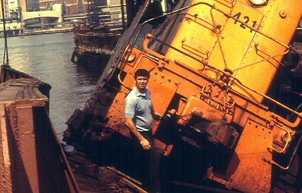 |
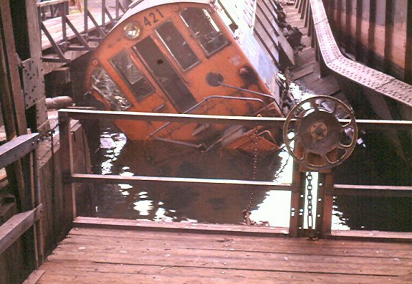 |
 |
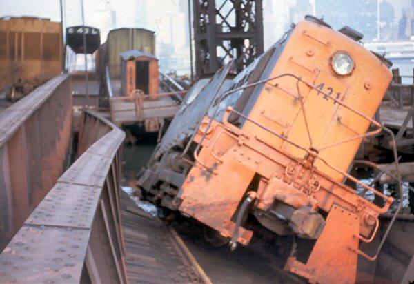 |
Transfer Bridge 5 - October 1972 courtesy of Steve Lynch / trainsarefun.com collection |
|
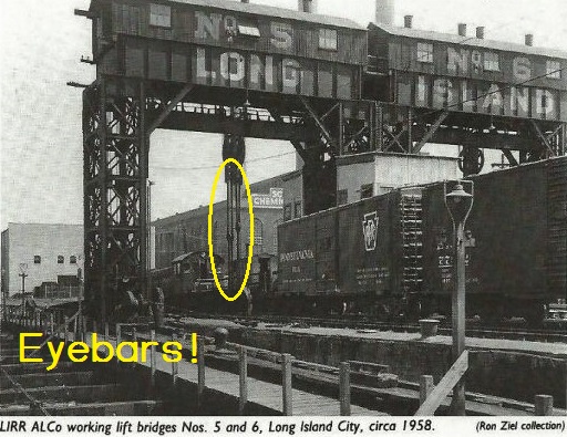 |
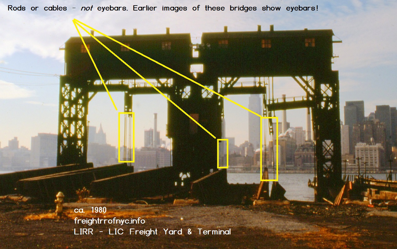 |
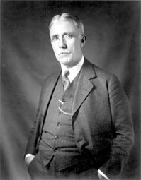 |
|
| James Benton French was born September 12, 1863 in New Hartford,
New York.
Beginning in 1886, he began his career in engineering and construction for the Missouri, Kansas & Texas Railroad. In 1888 he became draftsman and assistant engineer for Pencoyd Iron Works. In June 1891, he married Flora Williams and had two children: Thomas M. and William G. From 1892 through 1898 he was bridge engineer for Chesapeake & Ohio Railway. In 1899 & 1900 he designed bridges for the New York, New Haven & Hartford Railroad. In 1900 he was appointed bridge engineer for the West Virginia Short Line Railroad (to become a part of the Baltimore & Ohio Railroad system). In 1901, he returned to New York and was appointed as bridge engineer for the Atlantic Avenue Improvement of the Long Island Rail Road and remained with the LIRR until 1908, at which time he entered private construction & engineering practice, and consulted for the Long Island Rail Road in regards to the Bay Ridge Improvement (65th Street Terminal & Yards) , and including the elimination of grade crossings and construction of new terminals in the boroughs of Brooklyn & Queens. He was also consultant for the Lehigh Valley and Hudson & Manhattan Railroads, as well as numerous other railroads. He passed away on December 3, 1947. |
.
Tracking the Contained
Apron Bridges
Please note: most of the dates for removal of the transfer bridges are based on Thomas Flagg's notes and images accumulated over the past 25 years. Space limitations prevented printing many of the photos in the published issues of "Transfer", but a float / transfer bridge image album is forthcoming on this website. PMG
.
New York Central Railroad - West 69th Street, Manhattan, NY
The very first Overhead Suspended Contained Apron "French Type" transfer bridge was located at New York Central's West 60th Street Yard, but more accurately, it was located at the foot of West 69th Street in Manhattan (the railroad yard was comprised of almost a dozen city blocks running along the Upper West Side of Manhattan. This transfer bridge led a very useful life and proved the soundness of James B. French's design, and has apparently never been modified or altered in any way.
Unique to this location, was the fact that all three major types of transfer bridge of the era were represented in a single location: Contained Apron or "French type" (north), Pontoon (center) and Separate Apron "Bensel type" (south).
With declining rail freight traffic in the New York Metropolitan Area, and the disastrous New York Central & Pennsylvania merger into Penn Central in 1968, the transfer bridges was taken out of service . It was left intact, with the exception that the rails were lifted about 1982. Sometime after, the wood approach decking was removed, isolating the steel bridge and superstructure from land.
Research and write-ups by our very own author Thomas Flagg, has caused this transfer bridge to be listed by the State Historic Preservation Office as eligible for the National Register of Historic Places. However this historic engineering landmark was not physically protected in any way, and was slowly being destroyed by weather and vandalism. Around the year 2000, during renovations of Riverside Park (which followed the example of "Gantry Plaza" State Park in Long Island City, Queens); the transfer bridge has become a prominent feature of the park. As of 2003, it has since been listed on the National Register of Historic Places.
Co-author Paul Strubeck wisely visited the location to record the structures. Images of the neighboring pontoon type and the remains of the Separate Apron type can be viewed in their respective chapters. This location has been undergoing stabilization measures to prevent any further deterioration of the structure, for future restoration pending funding.
|
|
| .
. |
|
|
| .
. |
|
|
| .
. |
|
|
| .
. |
|
|
| .
. |
|
|
| .
. |
|
|
.
.
Long Island Rail Road & New York, New Haven & Hartford Railroad - 65th Street / Bay Ridge, Brooklyn, NY
These transfer bridges located at Bay Ridge were in constant service from the time of their construction right up until the Penn Central merger of 1968. It was at this time that Penn Central chose to send all its New England traffic via a circuitous northern route. The float bridges were taken out of service in 1968, and were demolished and completely removed between 1972 and 1973.
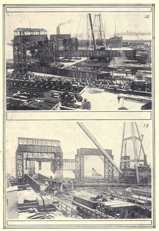
The Development of Carfloat Transfer Bridges in New
York Harbor, J. B. French - 1917
Plate VII
| 12: 32 ton Main Girder being placed by floating
derrick 13: Towers & Suspender Frames under construction |
P. M. Goldstein
collection
added 02 January 2012
New York Central Railroad - Weehawken / West Shore Yards - Weehawken, NJ
Three more contained apron bridges were constructed circa 1913 for the New York Central Railroad at its West Shore / Weehawken Yard in New Jersey (French, 1917). These were constructed on either side of one earlier transfer bridge of separate apron design built in 1905 and constructed in an "all enclosed" transfer house wood gantry house. They too were all taken out of service sometime after the Penn Central merger of 1968 and torn down not long after, although the steel towers of two of these transfer bridges remained standing for some time.
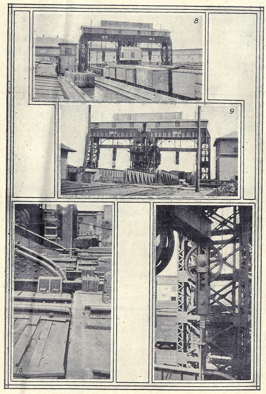
The Development of Carfloat Transfer Bridges in New
York Harbor, J. B. French - 1917
Plate V
| 8: View from the water 9: View from land 10: Detail of float connection 11: Detail of suspender frame & counterweight attachment. |
P. M. Goldstein
collection
added 02 January
2012
.
Additional photos of these transfer bridges in the distance and the supporting float yard in the foreground can be found on:
P. 66; "New York Harbor Railroads in Color, Volume 1"; (T. Flagg, Morning
Sun Books, 2000).
P. 69; "New York Harbor Railroads in Color, Volume 2"; (T. Flagg, Morning
Sun Books, 2003).
.
.
Lehigh Valley Railroad - Jersey City, NJ
The Lehigh Valley Railroad constructed two transfer bridges of the contained apron design at Jersey City circa 1920 (according to an LVRR Annual Report). These were removed sometime during the 1970's. Photos of them in service can be found on
P. 56, 57; "New York Harbor Railroads in Color, Volume 1"; (T. Flagg, Morning
Sun Books, 2000).
P. 58, 60; "New York Harbor Railroads in Color, Volume 2"; (T. Flagg, Morning
Sun Books, 2003),
the Archer and Yanosey "Morning Sun" books on the Lehigh Valley Railroad,
and
RMIG East Coast bibliography which can be found in inserts in "Transfer"
issues #10 & #11.
.
.
Erie Railroad - Jersey City, NJ
The Erie Railroad constructed two transfer bridges of this design at their Jersey City location in 1927 (Port Authority Annual Report). These were probably removed in the 1970's as well. Images of these bridges can be seen in
P. 49; "New York Harbor Railroads in Color, Volume 1"; (T. Flagg, Morning
Sun Books, 2000).
Volume 1, #2, Erie Lackawanna Historical Society publication "The Diamond".
.
.
Pennsylvania Railroad - Harsimus Cove, NJ
As mentioned above, the Pennsylvania Railroad constructed two at their Harsimus Cove Terminal in 1929, replacing bridges removed to make way for their Harborside Terminal.
These bridges were removed sometime after 1965. For photos, refer to:
Pages 46 & 62; "Keystone" Spring 1992 (Witmer's article on PRR tugboats)
.
.
New York Central / City of New York - Bronx Terminal Market - Bronx, NY
Another contained apron transfer bridge was built on the Harlem River by the City of New York for the Bronx Terminal Market circa 1925, but did not enter service until 1935 (new York times, October, 1935, page 28). It was removed in the mid nineteen seventies, after being out of service for many years.
.
.
Long Island Rail Road
- Long Island City, Queens, NY
Possibly the most well known examples of the contained apron design are located at the former Long Island City Terminal of the Long Island Rail Road.
The transfer bridges are still highly visible from Manhattan. The Long Island Rail Road's Mallery transfer bridges that were originally constructed at this location in 1903, and subsequently rebuilt by French in 1905 and 1906. Apparently these continued in service for some time, presumably due to the LIRR's chronic poverty of the era. In fact for many years the slowness of the bridging of carfloats at this location was so well known in rail-marine circles as to have become a standard joke at the meetings of the Railroad Club of New York (e.g.: March, 1904 Proceedings of the Club, p. 1-4).
In 1925, the Mallery type transfer bridges were completely reconstructed to French's contained apron design. The new transfer bridges were numbered from north to south:
1 & 2 (at the foot of 48th Avenue),
3 & 4 (formerly at foot Hunters Point Avenue & demolished), and
5 & 6 (at foot of 50th Avenue).
An easy way to tell the sets of transfer bridges apart in images is by the size of the control cab. 1 & 2 have a large control cab: four windows facing the East River whereas 4 & 5 have a small control cab: two windows facing the East River.
An interesting description of the rebuilding of the first two transfer bridges was published in the LIRR Information Bulletin in 1925, and subsequently reprinted on p. 61 of Kalis' 1993 article on LIRR Operations. Kalis provides color photos of these bridges; and it is clear from inspection of these that the overhead structure was rebuilt at some point, perhaps in the 1950's.
In or around April of 1970 (but definitely before 1976 on which date Conrail took over operations of the various bankrupt Class 1 railroads in New York Harbor, and subsequently abolished carfloating operations on this date. It was also upon this date that LIRR closed the yard) Transfer Brdige #5 collapsed under use. The details and failure analysis can be read here.
The Long Island Railroad transfer bridges at this location were last used in 1976 (Rails Northeast, September 1976), and they were simply left in place, with the overhead apparatus intact.
Prior to their restoration, some portions of the steel bridge spans were cut with torches and stolen by scrap theives. Uninformed observers thought the remaining structures were some form of railroad gantry crane and not the transfer bridges that they actually are. The location has since been stabilized and restored, and the transfer bridges and their gantries now serve as the centerpieces of "Gantry Plaza" and the transfer bridges' actual use is irrefutable. Gantry Plaza is a waterside promenade that was constructed as part of a massive redevelopment of the Long Island City Waterfront.
The following set of images were purchased on eBay in 2013 and quite frankly, I forgot I had them. Paul Strubeck was kind enough to make digital scans from the original 35mm slides. Most are of Bridges 1 & 2, but a couple of 4 & 5 are snuck in. Unfortunately, they are unmarked as to photographer, but are dated 1976 at just about the time they were removed from service:
|
|
| .
. |
|
|
|
. . |
|
|
| .
. |
|
|
| .
. |
|
|
| .
. |
|
|
| .
. |
|
|
| .
. |
|
|
| .
. |
|
|
| .
. |
|
|
| .
. |
|
|
| .
. |
|
|
|
. . |
|
|
|
. . |
|
|
| .
. |
|
|
| .
. |
|
|
| .
. |
|
|
| .
. |
|
|
| .
. |
|
|
| .
. |
|
|
| .
. |
|
|
While the contained apron bridge spans and counterweight cables have been removed. All else considered, they look quite attractive! Bridges 1 & 2 have short concrete decks in place of the bridge spans and surrounding the gantry allowing very detailed inspection of the construction. Bridge 5 & 6 remain isolated from public access.
.
|
|
| .
. |
|
|
| .
. |
|
|
| .
. |
|
|
| .
. |
|
|
| .
. |
|
|
| .
. |
|
|
| .
. |
|
|
.
.
Additional images can be seen in Thomas Flagg's books:
P. 63, 64. 65; "New York Harbor Railroads in Color, Volume 1"; (T. Flagg,
Morning Sun Books, 2000).
P. 65, 66; "New York Harbor Railroads in Color, Volume 2"; (T. Flagg, Morning
Sun Books, 2003),
P. 38; RMIG Transfer Issue #14
"On Waterfronts of the Present, Rail-Bridge Relics of the Past" (Christopher
Gray, The New York Times. November 7, 2004)
.
..
U.S. Navy - New York Naval Shipyard "Brooklyn Navy Yard"
Yet another contained apron transfer bridge was built in the Brooklyn Navy Yard following the yard's expansion and reconstruction in 1941. This contained apron bridge replaced a pontoon bridge originally at this location and used solely by the Navy Yard.
In the late 1930's, the U.S. Department of the Navy began condemnation proceedings against the tenants of the neighboring Wallabout Market in anticipation of expanding the Brooklyn Navy Yard. Most of the pier stations (no trackage) on the Wallabout Canal were occupied by several railroads. Please refer to the Wallabout Union Terminal page of this website for detailed information on this event. By late 1941, all of the tenants had vacated and the Navy Yard was expanded.
The contained apron transfer bridge would be constructed and was operated by a Navy Yard employee, but actual carfloat service to this location was contracted to the Brooklyn Eastern District Terminal (BEDT), on a renewable yearly basis. It is believed that BEDT received with contract with preferential consideration, as the BEDT had constructed their own carfloat terminal next to the Navy Yard in 1935 (Wallabout Market Terminal), but was forced to abandon it for the expansion of the Navy Yard. For more information refer to: BEDT - Wallabout Market Terminal)
This contained apron bridge itself was then converted to a Pontoon type after 1980. Following the dissolution of the Brooklyn Eastern District Terminal / New York Dock in August 1983, the New York Cross Harbor Railroad (which took over New York Dock's Bush Terminal operation), received a contract to sporadically provide carfloat service to this location for a rail car rebuilding firm (NEMCo) beginning mid -1980's. This customer was switched once a week. Service ended by 1992 and once the contract ended, so did all carfloat service to this facility.
The tower gantry structure was left in place despite being converted to a pontoon bridge and remains standing to this day. John McCluskey, a fellow rail-marine enthusiast, has compiled an excellent and extensive image album of this location from photos taken in 2006. His photos may be viewed at: Railroad Picture Archives, John McCluskey: Structure 713 - Brooklyn Navy Yard.
.
.
James B. French's book on
the Development of Carfloat Transfer Bridges in New York Harbor -
1917
I have been fortunate to procure an original issue of: "The Development of Car Float Transfer Bridges in New York Harbor". This information was originally published in the proceeding of the Connecticut Society of Civil Engineers for 1917.
Not only is this booklet valuable historically as there are not many copies that survived, but is is valuable for its wealth of information as well. It describes the evolution of the float bridge / transfer bridge in New York Harbor, to even include a detailed reference to the catastrophic failure of one of the original Long Island Railroad float bridges at Long Island City mentioned above; and contains the installation types and dates of the contained apron float bridges up until the time of publication.
This data is now incorporated into this websites page: "Comprehensive List of Float Bridges of New York Harbor".
It is with great honor I share this booklet with the rest of the rail marine community. I have also included enlarged scans of the illustrations for better viewing. Please feel free to contact me at bedt14@aol.com if you need larger, high resolution scans of the diagrams for modelling or research.
|
|
|
|
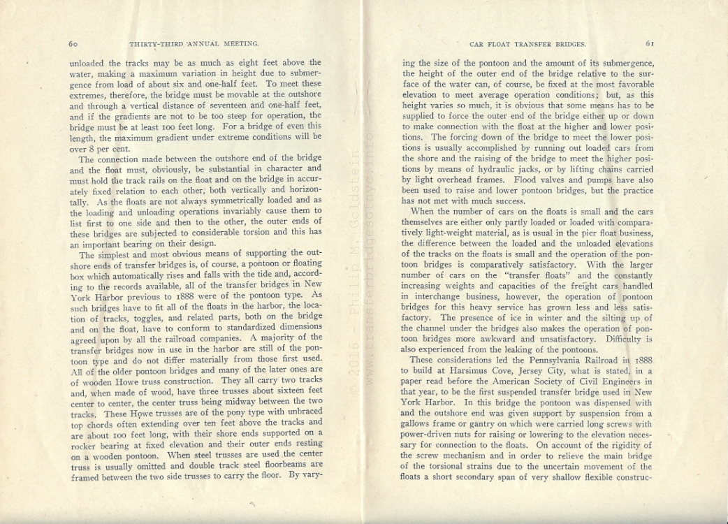 |
|
|
|
|
|
|
|
|
|
|
|
|
|
|
|
|
.
If you would like to learn how carfloats
were moored to the float bridges and the proper procedure for such, please
see
Carfloat
Mooring Procedures, and how the cars were unloaded:
Carfloat
Unloading Procedures.
.
.
.
Overhead Suspended
Single Span Cable Lift a/k/a "West Coast"
Type
.
| The West Coast Type | Design Characteristics & Comparisons | 207th Street - IND / NYCTA |
| 65th Street - NYNJ Rail | The Temporary Carfloat Modification | Design Elements & Details |
.
..
There is a fourth design type of transfer bridge that is currently located in New York Harbor. It is sort of unique in its design as it has some attributes from various designs of bridge but omits others. This design was formerly believed to be a variant of the type of transfer bridges commonly seen in Chesapeake Bay operations. However, according to John Teichmoeller, a leading authority and historian on the "Baltimore" type of transfer bridge, he pointed out several differences between this design and others. He also noted that that this particular design was utilized more frequently on the West Coast than in Chesapeake Bay.
Upon reviewing the HAER Study for the Locust Point, MD transfer bridges (ex-Chesapeake & Ohio), it became obvious John had made several good points and was more than correct.
And, I apologize in advance if a little of my "Atlantic side" pride shows because we really cannot refer to it a 'West Coast' type for our discussion, (like bummer, dude) as we are on the East Coast!
.
.
Design Characteristics
and Comparison
To begin, it was first necessary to compare the design with
others already established:
The end of the span of a Mallery as well as the Baltimore types have the swiveling head block (carfloat-span interface). The 207th Street and 65th Street type does not.
The Baltimore type utilizes a stacked "pick up" system of counterweights
that lifts increasing numbers of counterweight which are stacked and cable
connected to one another to compensate for live load, after the deadweight
capacity was exceeded.
The Mallery design nor the 207th Street or 65th Street designs
has them.
The 207th Street and 65th Street bridges lacks either separate (Bensel) or contained (French) aprons.
The 207th Street and 65th Street bridges are comprised of a single span, two tracks wide and not two individual spans side by side such as the French, Baltimore or Mallery designs.
As such, the design of this transfer bridge is that it has a single overhead counterbalance gantry, unlike the two gantries for Separate Apron (Bensel) design (one gantry for the main span, one gantry for the apron). While the Contained Apron (French) design had a single gantry to house the threaded rod lifting mechanism for lifting the dead load of the span, this housing and and even this lifting mechanism is absent for this newer design.
The type of transfer bridge we are discussing, simply put, is overhead suspended cable lift transfer bridge of single span. It is understood that some of these cable lift transfer bridges are equipped with electric winches for raising and lowering the spans, but some (like the 207th Street location) were manually operated.
Once the span is lifted or lowered to and matched with the height of the carfloat and the carfloat attached to the span, the lifting cable is slacked off and disconnected (via a simple hook clevis and eye) . The counterbalances are now taking up the dead load and partial live load via larger cable and sheave system, and with the carfloat taking up a partial live load. As the counterbalances are independent to one another, the bridge span is free to incur torsional twist from the other side and each counterbalance would act accordingly and opposite the other in relation.
.
To the best of our research, this overhead gantry type design did not find widespread use in New York Harbor early on, with Bensel (separate apron) & French (contained apron) types dominating the overhead style. The only known historical example to have been constructed in the New York Harbor area was at IND / NYCTA 207th Street Yard in circa 1930.
As best as can be discerned, this location's span was manually lifted and lowered via a pair of chain falls, with one on each side of the span. Once a carfloat was "bridged", the lifting chain was slacked, and detached from the bridge span and with the counterbalances taking up most of the load and the carfloat taking up the remainder.
Why this design was chosen over any others remains a mystery. The overall appearance of this design of transfer bridge looks lighter duty than Bensel or French designs, and this could be a determining factor. As this location saw use only for the delivery of new or rebuilt subway cars or the shipment of obsolete ones, it was used very infrequently, and this would make sense in this choice of design, but this is not confirmed.
Quite frankly, information about this location is sorely lacking. We have been able to put bits and pieces together and find a few images, but that is it.
.
|
|
| .
. |
|
|
| .
. |
|
|
.
.
65th Street / Bay Ridge Yard
- The old becomes new again!
Now, let us leap forward to 1999. Interestingly enough, is would be this design that was chosen and used in the construction of the newest pair of transfer bridges installed in the New York Harbor area in more than half a century. These transfer bridges were constructed by the New York City Economic Development Corporation at 65th Street (also known as Bay Ridge Yard).
This 65th Street location as discussed previously in the Separate Apron chapter, was the location of four Separate Apron (Bensel) types: named "Abie", "Bennie", "Charlie" & "Davy" and built in 1916 by the New York, New Haven & Hartford Railroad and used until 1968. At such time the float bridges were abandoned, but demolition not taking place until 1972.
Returning to the present and the current 65th Street transfer bridge design, these "new" transfer bridges would be very similar in operation to the transfer bridge constructed at 207th Street, but with two notable improvements: electrically operated winches were used to raise or lower the span, and the counterweight capacity increased for modern day freight cars.
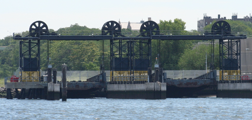
65th Street, Brooklyn NY - circa 2009
Looking east.
P. F. Strubeck
photo
added 03 February 2010
.
.
Temporary Modification
needed for Carfloats
Despite the current 65th Street transfer bridges having been built in 1999, these transfer bridges would remain unused for about a decade. In 2009, following a series of equipment compatibility tests between the existing carfloats of the New York New Jersey Rail roster, and the transfer bridges at 65th Street revealed that minor modifications would be necessary, but it was not due to a defect in design in the transfer bridge.
As the rail used on the transfer bridges when constructed in 1999, was of a modern heavier weight rail (115 pounds per yard), and as the rail installed on the older carfloats was slightly lighter (90 pounds per yard). This resulted in an approximate 1-1½" height difference in height of the railheads:
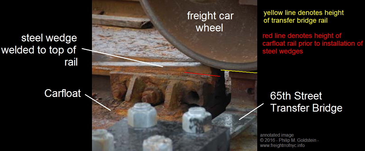
image courtesy of Railroad Construction Company
annotated by
author
added 06 February 2016
.
This difference in rail height is a common occurrence in normal land based railroad construction when two different 'weights' of rail are joined, such as in the case of when moving from heavily used main line trackage to a lighter spur line or industrial trackage. In this case, a compromise rail joiner a/k/a joint bar would be used, which keeps the top of the railhead at an even matched height (the difference taken up by additional ballast under the railroad ties or by shimming the tie plates). As the land based rails would be semi-permanently / permanently joined together, neither rail would be required to move.
But as the carfloat and transfer bridge are not permanently joined, something else had to be devised. Leaving the height difference in rail height would have resulted in shock damage and indentations to the freight car wheels, as well as stress fractures in the head and web of the rail installed on transfer bridge. And, as the rail on the carfloats was scheduled to be replaced in the near future, the modification had to remain cost effective and timely. The remedy was designed and installed by Railroad Construction Co. of Paterson, NJ. This modification was in the way of elongated steel wedges the width of the railhead and which were welded to the top of the carfloat rail at the carfloat / transfer bridge interface and which acted as ramps.
As the speeds of the freight cars on the carfloat and transfer bridge are minimal (usually no more than five miles an hour), this modification sufficed. Furthermore, as previously stated, this expedient field modification was only needed until the rail on the carfloats could be upgraded upon the release of further government funding the following year. But we digress from the topic at hand.
Returning to this design of the transfer bridge; and following the now successful tests, New York New Jersey Rail relocated their base of operations from Bush Terminal to 65th Street in July 2012. Obviously this overhead suspended cable lifted design must work because they have now been in service for four years with no known structural or design issues to date. If we recall our information correctly, the only interruption in service that took place was the need of new electric motors for the spans lifting winches.
These motors can be discerned in the P. Strubeck image above as the red objects mounted on the deck of the concrete platforms next to the counterweight towers. As the motors are mounted at track level, they were inadvertently submerged for the duration of the storm surge in Hurricane Sandy in late October 2012. To get some idea of the height of the storm surge, the high water mark was over the top yellow safety cages at the foot of the counterweight towers and approximately halfway up the counterweights. As you have read above, this same hurricane and storm surge would cause fatal damage to the Greenville transfer bridges.
NYNJ Rail or better yet, its parental agency: the Port Authority of New York & New Jersey has released a proposal for the construction of a new transfer bridge at Greenville, NJ. But until such time that transfer bridge is constructed and completed, these two examples of the cable lift types at 65th Street remain the newest transfer bridges to have been constructed in New York Harbor.
.
Details.. Design
Elements. A picture is worth a thousand
words!
It is at this time and with great appreciation that we welcome
two new contributors into the transfer bridge history group: Giancarlo Schiano
and Kevin Ciampi. Both of these gentlemen are professional engineers by trade.
They were instrumental in the study of many facets of the transfer bridge
operations of New York New Jersey Rail, including but not limited to:
inspection of 65th Street transfer bridges prior to activation;
post Hurricane Sandy repair or replace feasibility survey on the damaged Greenville, NJ transfer bridges;
the subsequent demolition of the Greenville, NJ transfer bridges;
and the removal, relocation and installation design of the 51st Street (Bush Terminal) pontoon float bridge to Greenville, NJ.
.
Through their involvement, many documents and images have come to light, enhancing this website, and especially this chapter. Matter of fact, it is their contributions that inspired it. The following images were taken by them in April 2014 upon an inspection and may not be reused without permission. Larger images for modeling or other purposes are available upon request: bedt14@aol.com
.
To better help the layman understand what key components of this design of transfer bridge are, please refer to the following image with legend.
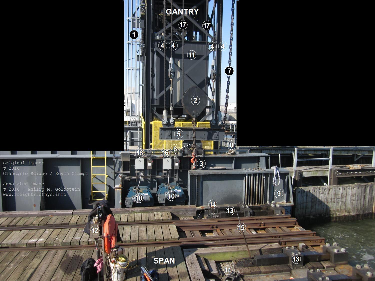
Number Key:
(Note: all items except #12 duplicated on each side of
span)
.
| 1) | Ladder to gantry, hoisting cable and counterweight cable sheaves | 10) | Carfloat mooring hawser winches |
| 2) | Span hoist tackle block | 11) | Counterweight |
| 3) | Hoist chain attachment (detached after span and carfloat are mated) | 12) | Hoist motor control box (rotating control knob for raise or lower) |
| 4) | Counterweight cable | 13) | Toggle bars (total 6 per span) |
| 5) | Equalizer beam | 14) | Toggle bar stop chocks (top two in place, bottom one removed) |
| 6) | Equalizer beam beam hinge | 15) | Toggle bar pry bar (removable) |
| 7) | Safety chain (tied back when not in use during bridge operation) | 16) | Winch motor control boxes (rotating control knob for tighten or slacken) |
| 8) | Safety chain clevis (chain is detached during bridge operation) | 17) | Hoist cables (up to gantry sheaves and back down to hoist winch drum and motor which is out of view behind gantry) |
| 9) | Safety girder |
.
.
|
Overall Construction |
|
|
| .
. |
|
|
| .
. |
|
|
| .
. |
|
|
| .
. |
|
|
| .
. |
|
|
| .
. |
|
|
| .
. |
|
|
| .
. |
|
|
| .
. |
|
|
.
.
|
Counterweights & Cables |
|
|
| .
. |
|
|
| .
. |
|
|
| .
. |
|
|
| .
. |
|
|
| .
. |
|
|
| .
. |
|
|
| .
. |
|
|
| .
. |
|
|
| .
. |
|
|
| .
. |
|
|
.
.
|
Span Hoisting Winch and Cables |
|
|
| .
. |
|
|
| .
. |
|
|
| .
. |
|
|
| .
. |
|
|
| .
. |
|
|
| .
. |
|
Gantry, Sheaves & Details |
|
|
| .
. |
|
|
| .
. |
|
|
| .
. |
|
|
| .
. |
|
|
.
.
|
Carfloat / Transfer Bridge Interfacing |
|
|
| .
. |
|
|
| .
. |
|
|
| .
. |
|
|
| .
. |
|
|
| .
. |
|
|
| .
. |
|
|
| .
. |
|
|
| .
. |
|
|
| .
. |
|
|
| .
. |
|
|
| .
. |
|
|
.
.
|
|
.
.
.
.
 |
Overhead Suspended Hydraulic Span Hydraulic Apron Type |
|
| A Transfer Bridge for the Twenty-First Century New York Harbor | A Carfloat for the Twenty-First Century for New York Harbor |
.
..
A Transfer Bridge for the
Twenty-First Century New York Harbor
In March 2014, the United States Army Corps of Engineers (New York District) released a public notice regarding permits for the dredging and construction of a new transfer bridge and control house at Greenville, NJ to augment the relocated pontoon type from Bush Terminal, and now called "Greenville Bridge #11".
The construction of the proposed transfer bridge as requested by New York New Jersey Rail, and called "Greenville Bridge #10", will have the gantry and control house to the north of the pontoon bridge's (Bridge #11) current location. While none of this is particularly revealing, a closer look of the detailed elevation drawing of the proposed transfer bridge is an eye-opener!
.
As it turns out, the proposed transfer bridge with apron has an overhead gantry for both span and apron like we are used to seeing with the Separate Apron (Bensel) types, but these two gantries are now inter-connected with additional horizontal girders on each side of the span forming a box as would be seen from the air.
A walkway on top of these girders allows access to the tops of either gantry for maintenance or repair without having to climb down from one gantry and climb up the other. This box like structure in itself is novel for transfer bridge construction, and would logically add stability to the two gantries.
.
Even more revolutionary is the span and apron height control method: hydraulic cylinders! The design calls for two cylinders (one on each side of the span) anchored at the top and hung down from the gantry at the outshore end of the span just before the apron hinge, and another pair of cylinders hung down at the end of the apron, just before the apron / carfloat interface. As the cylinders are facing down from an overhead stationary mount: extension of the respective set of cylinders would move the span or apron down. Retraction of the cylinders will raise the span and/or apron.
.
The control house appears to be a modest two story structure placed at the end of a walkway pier and past the apron, (as opposed to the smallish bay windowed operators shanty located in between the gantries on the older overhead supported transfer bridges). This in effect allows the operator an unhindered view of operations. The first floor of the control house will house the electrical cabinets, hydraulic pumps and machinery for the transfer bridge and apron, while the operators station would be located on the second floor, enclosed in glass with a 360 degree view out all four sides. If you need a comparison, think airport control tower!
.
Until such time (if) a second transfer bridge is needed, the operators controls for Bridge #11 will occupy the north side of second floor, with room for a second set of controls on the south side.
The proposed location of the control house is on the south side of the transfer bridge gantry and is so located should a need arise for an additional transfer bridge to be installed, where the current pontoon float bridge "Bridge #10" is now.
All in all, it is an exciting new design of transfer bridge. Frankly speaking, this author [PMG] cannot wait for its construction!
The following images are the most pertinent drawings (to this website) from that US Army Corps of Engineers Public Notice. The actual public notice, explanation, as well as additional drawings regarding dredging, pilings, bulkhead work and monopile fender system are omitted here. The unabridged filing can be read and viewed here:
NYNJ Rail Proposed Greenville Hydraulic Transfer Bridge - 2013.pdf
.
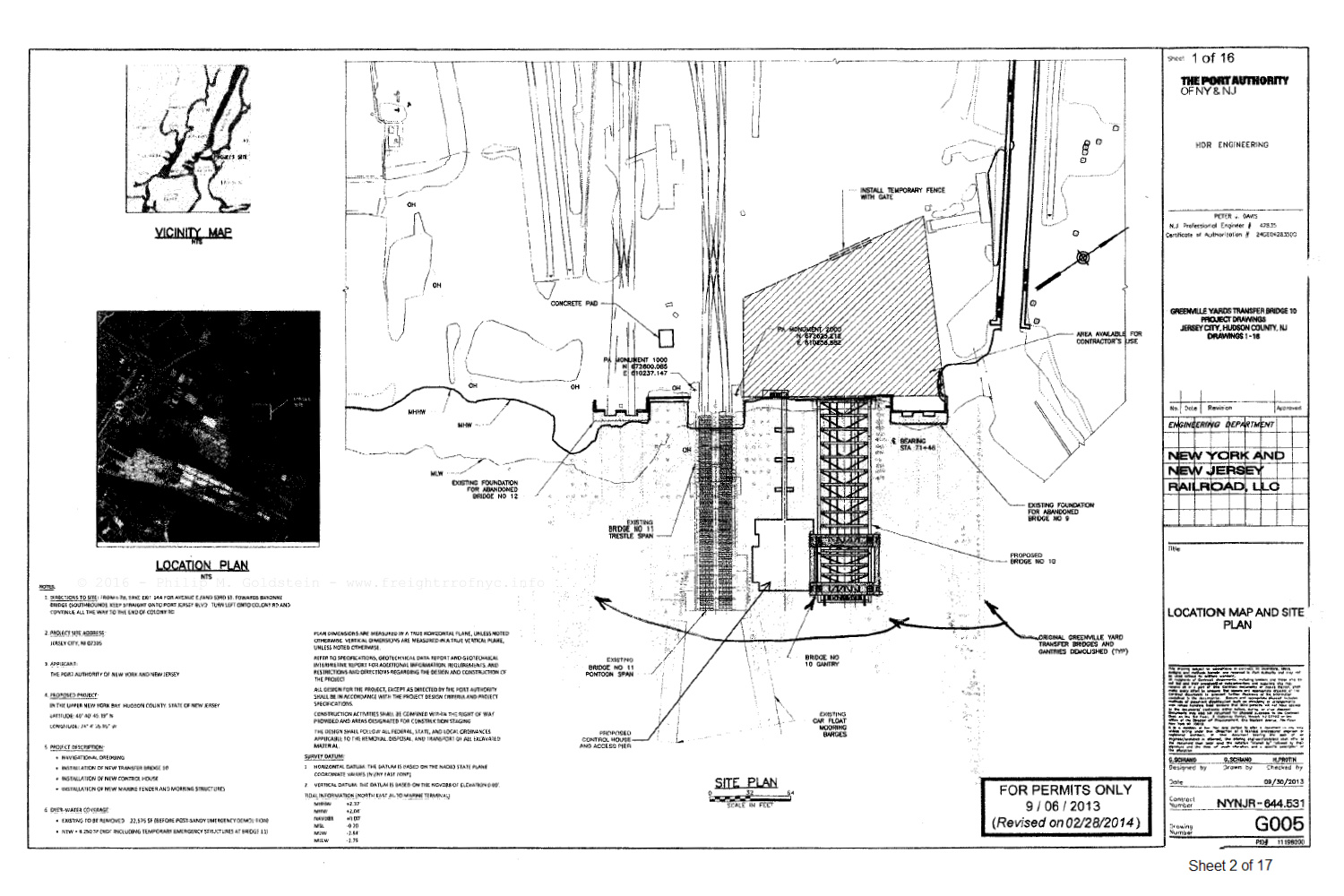
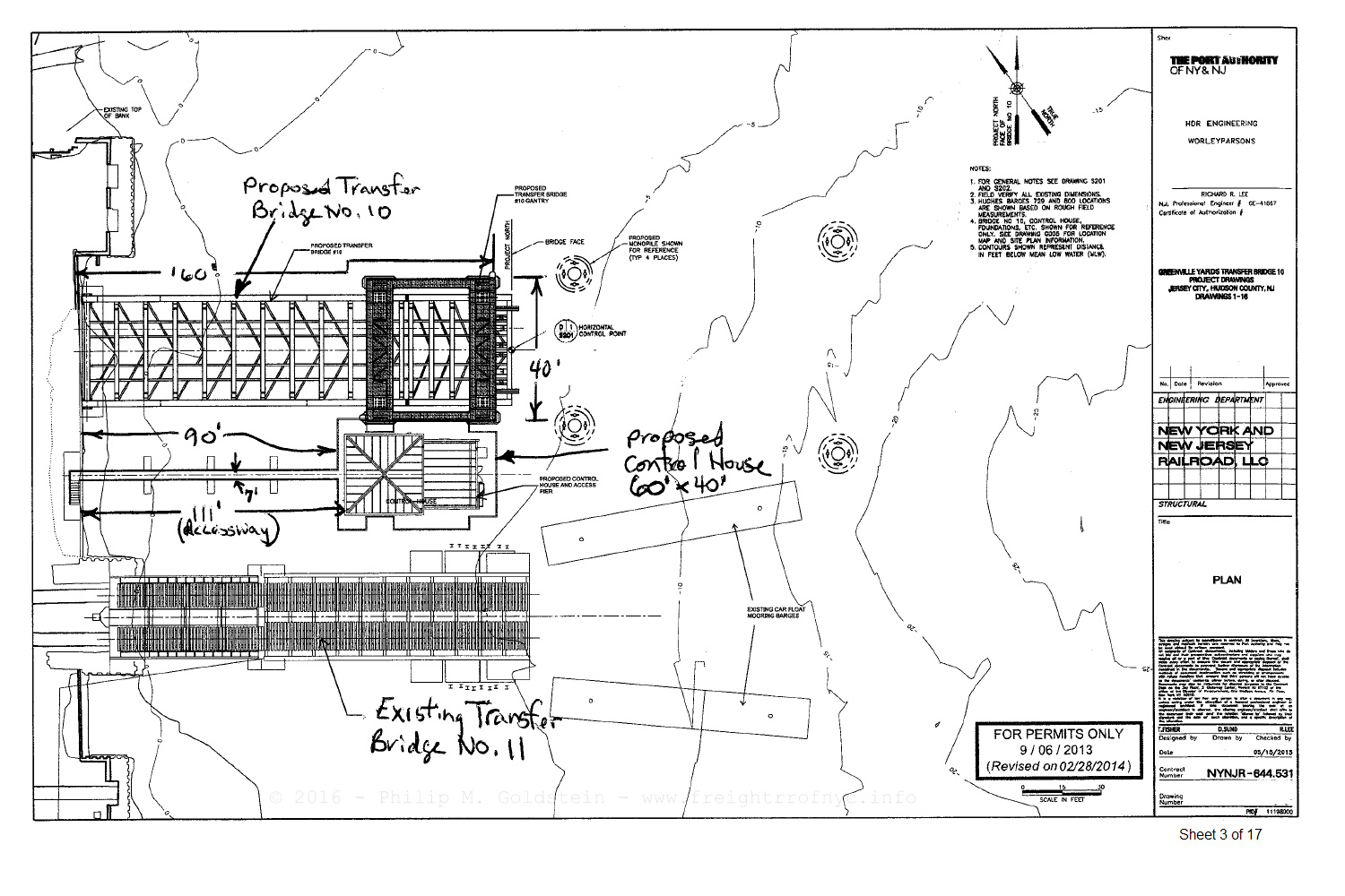
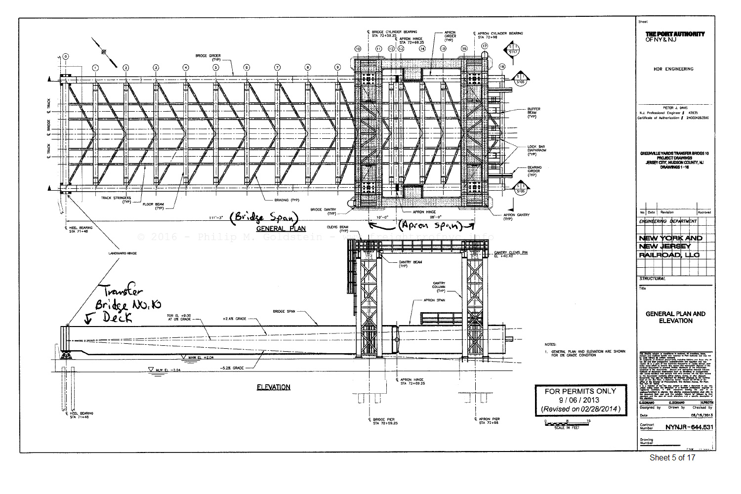
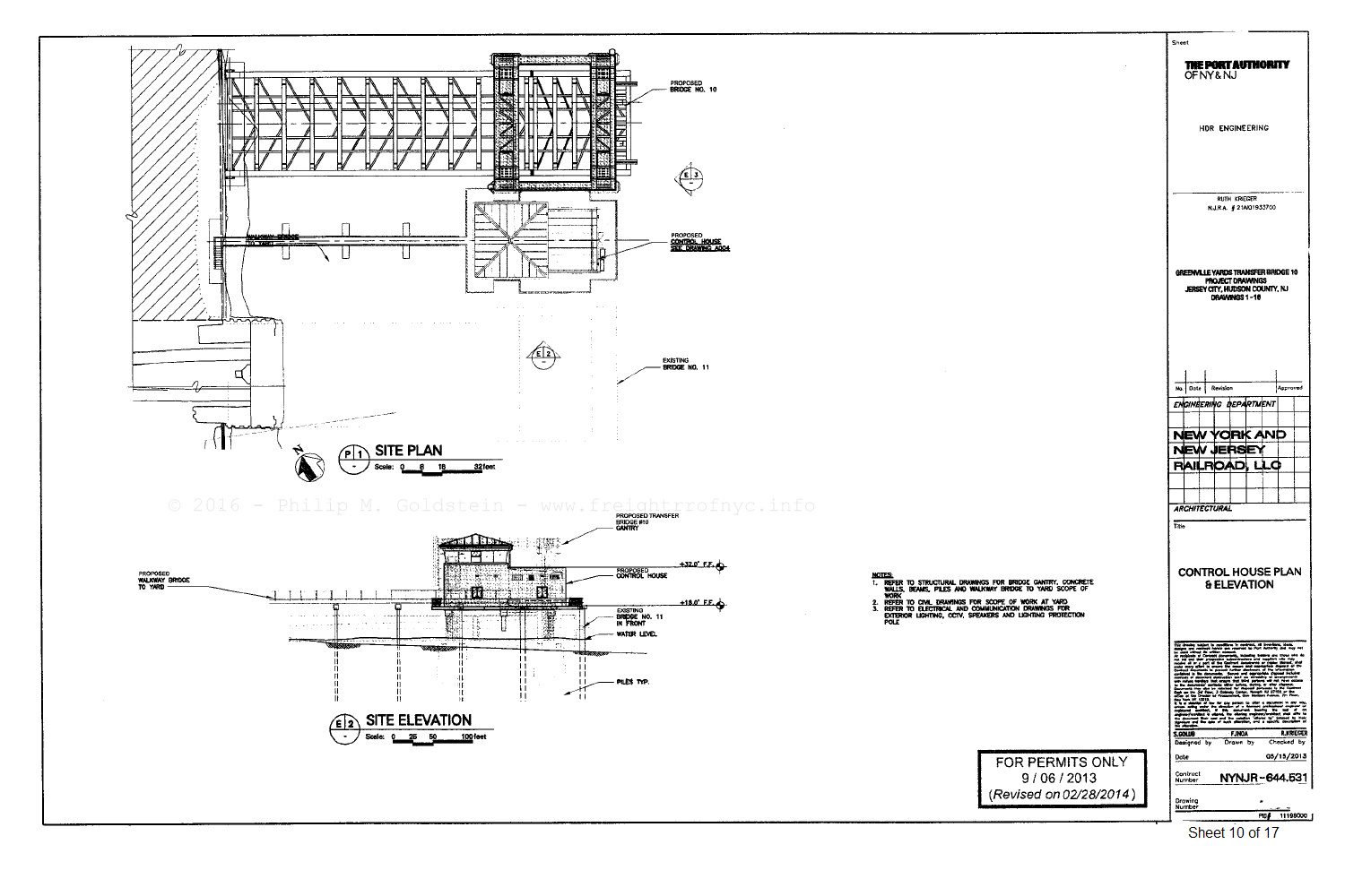
US Army Corps of Engineers - Public Notice for dredging
& construction - March 14, 2013
added 06 February 2016
.
..
NYNJ Rail Greenville Bridge 10 Construction Photos
The following images are courtesy of the management of New York New Jersey Rail. The display the ongoing progress of the new transfer bridge construction.
It appears, most of the proposed designs were approved, with the exception of the control house being moved to the top of the gantry.
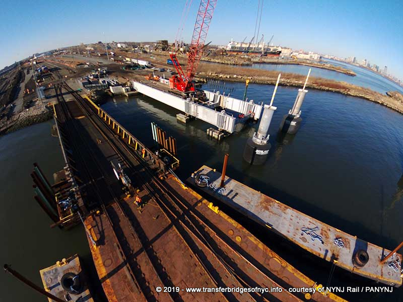 NYNJ Rail Greenville Bridge 10; Greenville, NJ - December 2017 bridge span & sub-deck being constructed. Looking west. courtesy of NYNJ Rail added 26 August 2019 |
| . . |
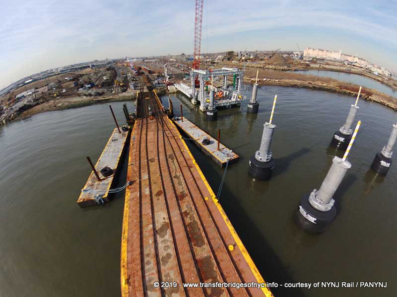 NYNJ Rail Greenville Bridge 10; Greenville, NJ - February 2018 bridge span constructed, support gantry being erected Looking west. courtesy of NYNJ Rail added 26 August 2019 |
| . . |
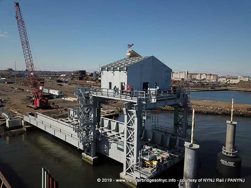 NYNJ Rail Greenville Bridge 10; Greenville, NJ - April 2018 bridge span, overhead hydraulic support gantry erected; machinery room being constructed Looking northwest. courtesy of NYNJ Rail added 26 August 2019 |
| . . |
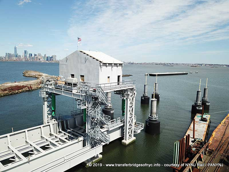 NYNJ Rail Greenville Bridge 10; Greenville, NJ - May 2018
bridge span, overhead hydraulic support gantry erected; machinery room constructed, roof being installed. Looking northeast.
courtesy of NYNJ Rail added 26 August 2019 |
| . . |
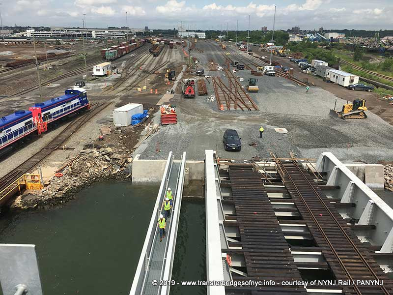 NYNJ Rail Greenville Bridge 10; Greenville, NJ Bridge span fitting out, lead tracks and crossover being laid. Looking west. courtesy of NYNJ Rail added 26 August 2019 |
| . . |
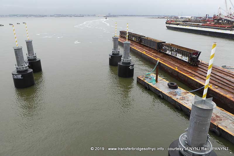 NYNJ Rail Greenville Bridge 10; Greenville, NJ
Mooring dolphins at transfer bridge. Looking east.
courtesy of NYNJ Rail added 26 August 2019 |
| . . |
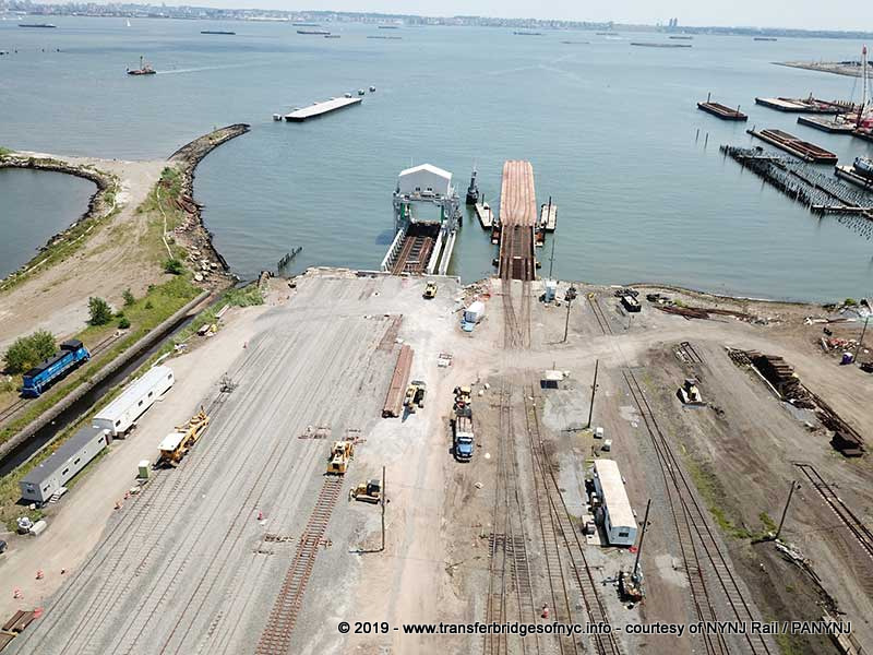 NYNJ Rail Greenville Bridge 10 & 11; Greenville, NJ Looking east. courtesy of NYNJ Rail added 26 August 2019 |
| . . |
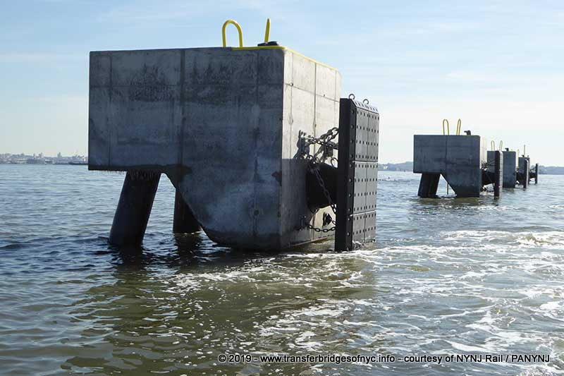 NYNJ Rail Greenville Rack; Greenville, NJ courtesy of NYNJ Rail added 26 August 2019 |
| . . |
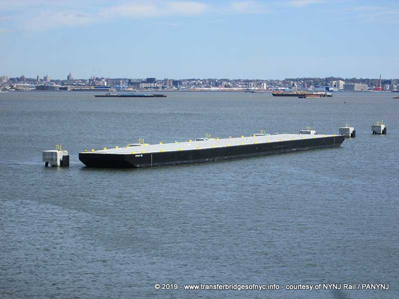 NYNJ Rail #100 at the Greenville Rack; Greenville NJ awaiting rail installation on deck. courtesy of NYNJ Rail added 26 August 2019 |
.
.
The Twenty-First Century
Carfloat for New York Harbor
To compliment this new style of transfer bridge, a new design of carfloat was drawn up as well., Bids were solicited, awarded and the carfloats are being constructed, even before the bid is awarded for the transfer bridge. The detailed construction drawings of these new carfloats were found on the Port Authority of New York and New Jersey website. The design is by WorleyParsons and NS Engineering. The successful bidder for constructing these two carfloats is Metal Trades, Inc of Yonges Island, South Carolina.
While building the carfloats before the transfer bridge kind of seems like putting the cart before the horse, it is not. And quite logical as I will explain.
The new carfloat is a four track transfer carfloat design, as opposed to the three track design we are used to throughout the history of carfloating in New York Harbor. This four track carfloat, will by design, increase the capacity of the carfloat requiring fewer tug/carfloat trips across the harbor, making the operation more efficient. The heady days of almost every Class 1 railroad moving carfloats multiple times a days working the entire harbor are over. There is a single route and only two points of loading & unloading. Therefore, one single carfloat of four track 370' design will have the capacity of eighteen 60' freight cars.
This is in comparison to the designed capacity of the 290' three track carfloat at fourteen 40' cars. When you take into consideration that the 40' freight car is no longer the industry standard and with longer freight cars the norm at 60' and even 75' on occasion, the longer freight cars reduce the overall number of freight cars carried on the older 290' carfloat. The best way to compare is the aggregate total length of the string of freight cars:
The 370 foot four track carfloat can handle eighteen 60 foot cars: 18 x 60' = 1,080 feet.
The 290 foot three track carfloat can handle fourteen 40 foot cars: 14 x 40' = 560 feet.
Therefore, in contrast:
The 370 foot four track carfloat has the capacity to carry twenty-six 40 foot cars, while
The 290 foot three track carfloat is limited to only eight 60 foot cars.
Please note: All figures above consist
of a solid consist of like length cars, i.e.: all 60' or all 40' cars. This
is unlikely in actual day to day operations.
So by design, a single 370' four track carfloat will at the
least take the place of a minimum of two fully loaded 290' three track carfloats
(requiring two trips), which is honestly about the amount of cars handled
on an average NYNJ Rail carfloat trip today, plus a little extra.
As the current three track carfloats were at least half a century old, they are nearing the end of their service life. Also, their overall design of the carfloat has remained unchanged since the turn of the century. When you consider all the research that has taken place in the fields of hydrodynamics and fluid dynamics during the last one hundred years or so, and further aided by computer modeling, research & design; the new carfloat hull contours will provide more efficient movement through the water.
Furthermore, upon the completion of these four track carfloats, only a minor retrofit to the tracks on the existing transfer bridges at 65th Street needs to be done. On the right track (the north track) of each transfer bridge will have a turnout installed instead of being a straight track. This in effect creates a mirror image of the existing left track turnout. That is all that will be required to accommodated this four track carfloat design.
If and when the new transfer bridges at Greenville are constructed, the apron will have both turnouts outfitted from the initial construction.
For the record, this four track type of carfloat has been successfully used before in rail-marine operations on the West Coast in Oakland & Alameda, California (Western Pacific, Southern Pacific and Santa Fe Railroads if I remember correctly) as well as in the Pacific Northwest in Alaska and I believe in Canada in British Columbia, as well. As that history is outside the scope of this website, further historical research is not forthcoming.
The unabridged filing can be read & viewed here:
NYNJ Rail Bid Solicitation for Four Track Carfloat - 2015.pdf
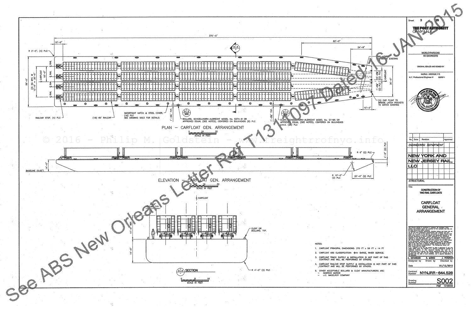
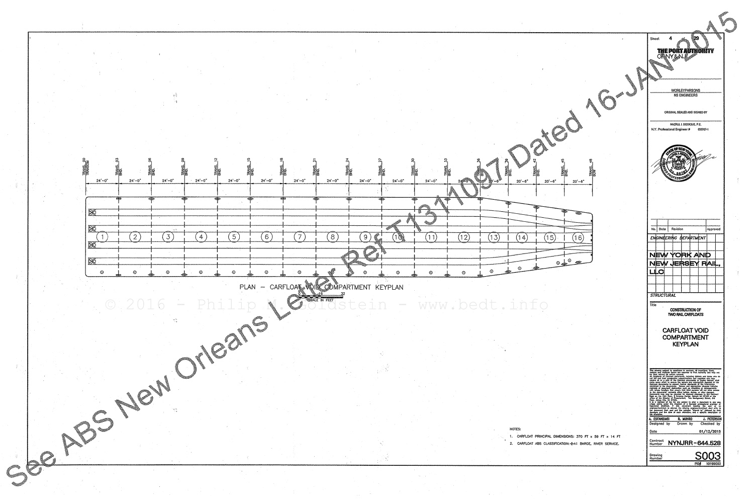
courtesy of Port Authority of New York &
New Jersey - Invitation for Bids - March 9, 2015, Bid #41672
"Construct and Deliver Two (2) Barge-Type Rail Car Floats for the Transport
of Rail Cars"
added 07 February
2016
.
.
.
.
This section of the page contains miscellaneous patent filings pertaining to transfer bridges and float bridges.
|
|
|
|
via Google Patent
Search
added 30 December 2011
.
.
Reference List &
Bibliography.
| Baxter R. J. & Adams, A. G. | "Railroad Ferries of the Hudson" - 1987 - (Lind Publications) |
| Bensel, John A. | "New Transfer Bridge, Harsimus Cove, Jersey City, NJ" - p 309-312, Volume 29 - December 1888 - (Transactions ASCE) |
| Chamberlain, W. E. | "Passenger and Freight Transfer System at Harlem River, NY" - p 202-216, Volume 5 - 1904 - (Proceeding of AREA) |
| Condit, Carl, W. | "The Port of New York: A History of the Rail & Terminal System from the Beginnings to Pennsylvania Station" - 1980 - (Chicago University Press) |
| duBosque, Francis L. | "The Floating Equipment of a Railroad" - 1915 (American Railway Engineering) |
| duBosque, Francis L. | discussion after a paper on Carfloat Strength - p 1-27, Vol.. 35 - 1927 - (Transactions of the Society of Naval Architects & Marine Engineers) |
| Dredge, James | "The Pennsylvania Railroad: Its Organization, Construction and Management" - 1879 - (London Engineering) |
| Droege, John A. | "Freight Terminals and Trains" - 1912 (McGraw - Hill) |
| Electrical Age | "Electrically Operated Transfer Bridge" - p. 355-356 - September 1906 |
| Engineering News | "Freight Transfer Bridge" - p. 67-68 Vol.. 23 - 1890 |
| Engineering News | "Standard Car-Transfer Bridge: New York Central & Hudson River R.R." - p 468-469, Vol... 46 - December 19, 1901 |
| Engineering News | "The 69th St. Transfer Bridge of the NYCHR&R RR at New York City" - p 770-774, Vol.. 66 - December 1911 |
| Engineering Record | "The Weehawken Transfer Bridges of the West Shore Railroad" - p 185-187, Vol... 57 - February 15, 1908 |
| Engineering Record | "The Oak Point Float Bridges on the East River" - p. 300-304, Vol... 61 - March 12, 1910 |
| French, James B. | "Development of the Car Float Transfer Bridges in New York Harbor" - 1917 |
| French, James B. | "Car Float Transfer Bridges in New York Harbor" - p. 75-96, paper 149 - January 10, 1918 |
| Flagg, Thomas R. | "The Transfer Bridge at the Port of New York: Part I: The Pontoon type"; Transfer 12, July - September 1995 (RMIG) |
| Flagg, Thomas R. | "The Transfer Bridge at the Port of New York: Part II: The Separate Apron type"; Transfer 13, July - September 1995; (RMIG) |
| Flagg, Thomas R. | "The Transfer Bridge at the Port of New York: Part III: The Contained Apron type"; Transfer 15, July - September 1995; RMIG |
| Flagg, Thomas R. | "The Transfer Bridge at the Port of New York: Part IV: Recap" Transfer 23, January - May 1998; RMIG |
| Flagg, Thomas R. | "New York Harbor Railroads in Color - Volume 1; 2000; (Morning Sun Books) |
| Flagg, Thomas R. | "New York Harbor Railroads in Color - Volume 2; 2000; (Morning Sun Books) |
| Flagg, Thomas R. | interview of F. Dayton, president New York Cross Harbor Railroad - 1993 |
| Flagg, Thomas R. | personal communication with Dave Pearce (former Lehigh Valley RR marine employee) - 1994 |
| French, James B. | reprinted from a proceedings of the Connecticut Society of Civil Engineers - 1917 |
| Historic American Engineering Records | #NJ49A; unknown date; (National Park Service) [note: there are errors in this compilation] |
| Joint Report of NY & NJ Port & Harbor Development Commission |
p. 238-242 -1920 (J. B. Lyon) |
| Kalis, Nicholas | "Long Island City Float Yard Operations" - p. 54-62 "Keystone" - Summer 1993 - (PRR Historical & Technical Society) |
| Mallery, Paul | "Bridge & Trestle Handbook, 4th ed." - p. 121-122 - 1992 - (Carstens Publications) [note: there are errors in this compilation] |
| Railway Age | "The Greenville Yard & Transfer Arrangements of the Pennsylvania RR - p. 397-403, Vol.. 39 - March 24, 1905 |
| Railway Age | "Floating Operations Rendered More Efficient" - p. 505, Vol.. 90 - March 7, 1931 |
| Rohde, William, L. | "Boxcar Navy" p. 8-28; September 1945 (Railroad Magazine Vol. 38, #4; Popular Publications) |
| Snow, J. P. | "Transfer Floats, Ferries and Bridges" - p. 160-166, 1901, (American Railway Engineering - 1892) |
| Sturm, Robert C. & Thom, William G. | "The New York Connecting Railroad", 2006, (Long Island - Sunrise Trail Chapter NRHS) |
| Tri-State Transportation Committee | "Rail Freight of the Tri-State Region" - August 1967 |
| Watkins, J. Elfreth | "History of the Pennsylvania Railroad" - 1886 |
| Witmer, Captain J. R. N. | "Steam & Saltwater" Vol.. 25 #1 "Keystone" (PRR Historical & Technical Society) |
| Bush Terminal | 207th St Yard (IND / NYCTA) | ||
| Degnon Contracting / Degnon Terminal... | Wallabout Terminal (DLW) | ||
| G & R Packing | Wallabout Station (Erie) | ||
| Atlas Terminal | Harlem Station (Erie / EL) | Procter & Gamble | Wallabout Union (PRR, NYC, LV, B&O) |
| Bronx Terminal (CRRNJ) | Harlem Transfer (DL&W) | Queens Subway Apartment & Loft Building | West 15th St Freight Yard (CRRNJ) |
| Bronx Terminal (LV) | Jay Street Terminal / Connecting | Rikers Island | West 23rd St Freight Sta (NYLE&W / Erie)... |
| New York Cross Harbor | West 26th St Freight Sta (B&O) | ||
| New York Dock | West 27th St Freight Yard (LV) | ||
| New York New Jersey Rail / Port Jersey | West 28th St Freight Sta (Erie / EL) | ||
| Brooklyn Wharf & Warehouse | North 1st Street Freight Sta (NYNHH) | 25th St / South Brooklyn Terminal (DLW) | West 37th St Freight Sta (PRR) |
|
Development of Car Float Transfer Bridges in New York Harbor |
Comprehensive List of Float Bridges located in New York Harbor |
||
|
. |
|||
|
Glossary of Definitions Indicative to Rail / Marine Terminal Operations in New York Harbor |
|||
Like what you see? Suggestions?
Comments?