 |
MODULE
|
This page is very much under construction. Send any suggestions or ideas you may have to Steve. (click on any image to see a larger version)
The decision to rebuild the Union and Southern as a modular layout was easy. The S-Mod standards provided a lot of the basic ideas. And, this layout could not have been built without experience with the BSG layout and the guidance of the club members who built the existing club modules. The hard part was where to find all the parts that were needed. Past experiences told me that the module legs were going to be the biggest challenge. I couldn't find either commercially available legs (at the right price) or a design for making module legs from scratch that I felt comfortable with. Even the commercial module kits that BSG had used in the past were showing signs of fatigue after a few years of use.
Then, a home repair project had me repairing the sump pump with PVC pipe and an idea was born. This stuff was easy to cut, just glued together, and was cheap enough that if I made a mistake or two along the way I could just throw away my mistakes and it wouldn't break the budget. At about that time the Builders Square Home Center was going out of business and I found a deal on 1 1/4" PVC pipe and couplers that I couldn't resist. So, without having all the details worked out I went home with a car full of supplies.
The first challenge was that PVC couplings are threaded with a pipe taper so that as you tighten a coupling you end up with a water tight joint. That works great for fixing the sump pump but I couldn't get enough movement to make this useful as a leg adjuster before the joint get tight. Then, Art Pratt saw what I was trying to do and came up with a solution. He put the couplings on his lathe and cut both the inside and outside threads flat.
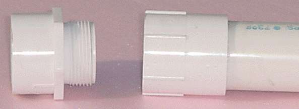
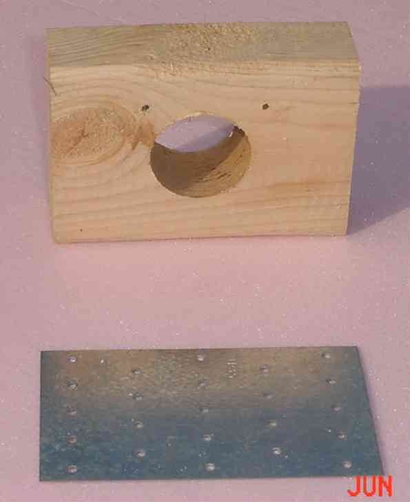
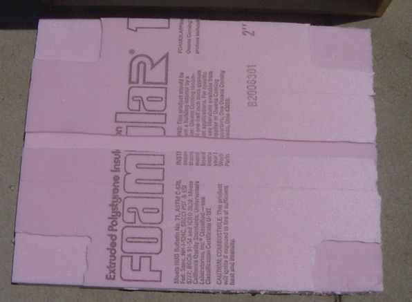
After Art worked his magic I ended up with a leg adjuster that was usable throughout the full length of the thread. This provides at least 1/2" adjustment on each leg. Next, I needed a way to connect the leg to the frame of the module. Again, after many trips to the local hardware stores I found what I needed at the Home Depot. Among the framing and deck building supplies They sell a 4"x5" flat brace that would work just fine as a stop to keep the legs from punching through the foam insulation top on the module.
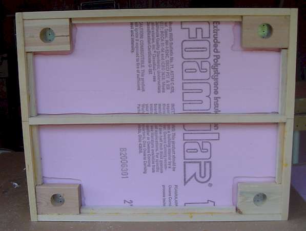
This assumed I had a leg pocket, and I did. To make the leg pockets I cut a 2"x4" into 5" lengths, then drilled a hole that would accept 1 1/4" PVC pipe. The outside diameter of this pipe required an approximately 1 11/16" hole. I used an adjustable diameter drill bit and experimented with various setting until I came up with a hole size that both allowed the legs to be easily assembled and held them snugly in place once inserted.
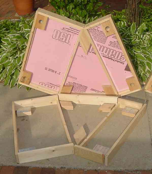
Corner Modules are built in two mirror image sections to maximize the amount of table top space available for scenery on the corners while still keeping them as compact as possible for transport. Here's a PDF format of the plans for the corner modules drawn in TurboCad 7.0.
The same set of parts are used for both the left hand and right hand module in each corner. The order of assembly determines if you end up with a left hand or tight hand section of the corner module pair.
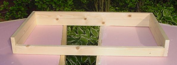
Start out by partially assembling the two main sections of each module. Stopping at this point allows adequate access to screw the interior bracing in place.
|
|
|
|
|
The brace for the inside corner of the module can be mounted on the larger of the two partial sections and needs to be positioned with it's point flush with the outside edge of the module as shown in the picture on the right. You can continue the assembly and connect the two halves of the module.
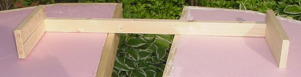
Follow this by attaching a brace on each section of the module for the back center of the module. This time, you need to keep the brace in far enough to allow room for the board to be connected flush with the outer edge of the module as shown on the left picture .


Home - Why S - Hirail - Scale - Module - Accessories - About us
Shows & Events - Trade & Sale - Join - Hints & Tips - Members info - Links
| For comments on, change request, or questions send E-Mail Message to the Webmaster All information contained on this site is © 1999 - 2006 Badgerland S Gaugers, unless otherwise credited. The views and opinions expressed in the Badgerland S Gaugers WWW Pages are those of the contributor, unless otherwise credited, and do not necessarily represent that of the club it's officers, directors, or the membership. The Badgerland S Gaugers do not offer any warranties, guarantees, nor assume any liability from the information contained on or referenced from this site. |