 |
Installing a Rectifier to create a DC locomotive |
The American flyer will run on AC or DC directly as made. The down side is the E-unit in the tender or boiler will not function 100 percent of the time. Occasionally they will "hang up" and create a condition called "tender thumping". The E-unit can be locked in a specific direction. When running DC the E-unit can be magnetized which can hinder or eliminate reversing capability which could require de-magnetizing or E-unit replacement. Changing the system to "DC only" eliminates the directional problem due to e-units. the only condition required is the power going to the track must be DC and reversible as well. DPDT switch after the added (10A minimum) rectifier between the AC transformer and the track solves the problem. (Calculate rectifier capacity by using 4A times the locos that will be running at one time)
Let's start with the tools needed:
1) Screwdrivers, both cross point (Phillips) and regular point
2) Wrench for Wheel Driver Screws. Screwdriver style socket is recommended to avoid scratches.
3) Soldering iron and rosin core solder
4) Heat shrink tubing
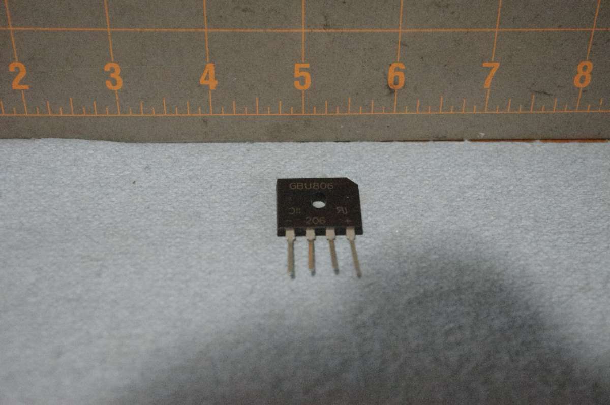
5) 6 amp min to 8 amp max rectifier for loco Bridge Rectifiers | Diodes | Electronic Components Distributor DigiKey
6) Plastic sandwich bag for the removed parts, they are replaceable to return the unit to factory specs. Label the bag with a permanent marker for future reference
7) JST connectors for future disconnect of the loco tender combination (optional)
8) Couple feet of 20-24 gauge wire
9) Cradle for loco to disassemble without damage (optional)
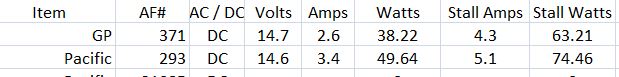
| Measurements taken. Individual units may vary by condition |
|
Step 1) Tender disassembly
|
|
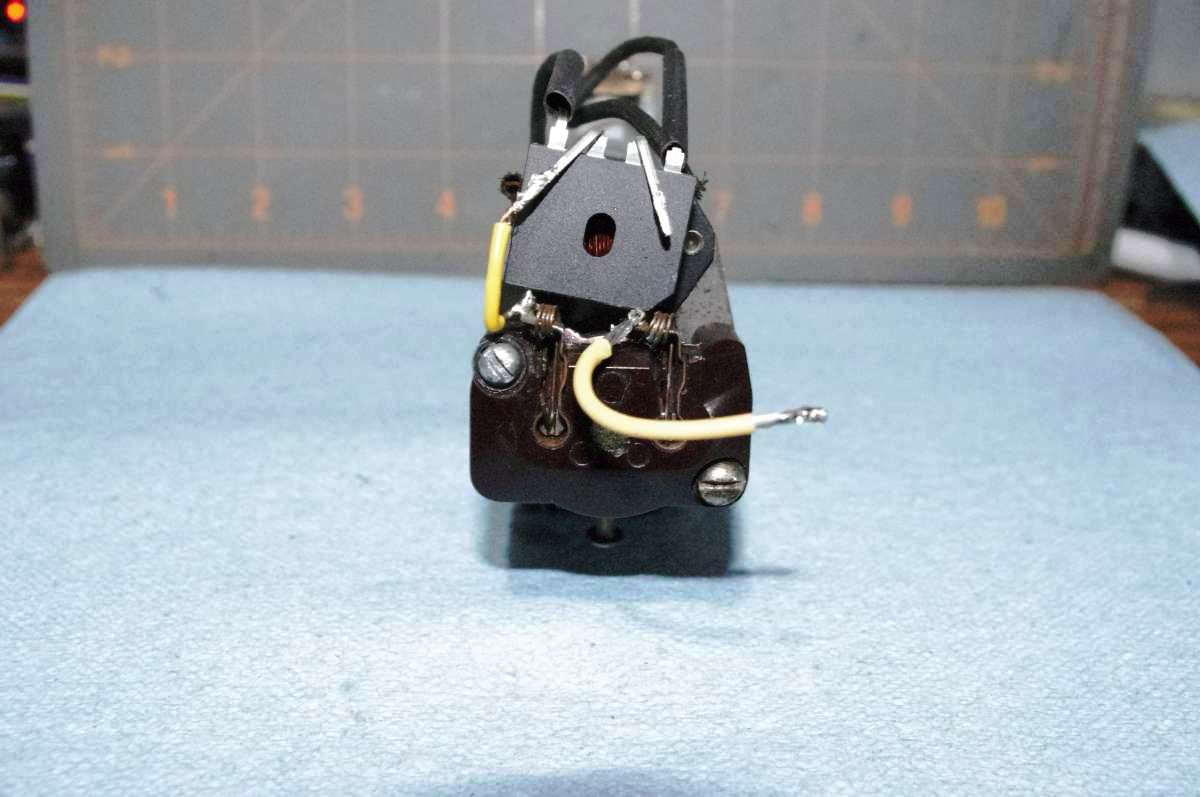
Step 2) Tender upgrade
|
|
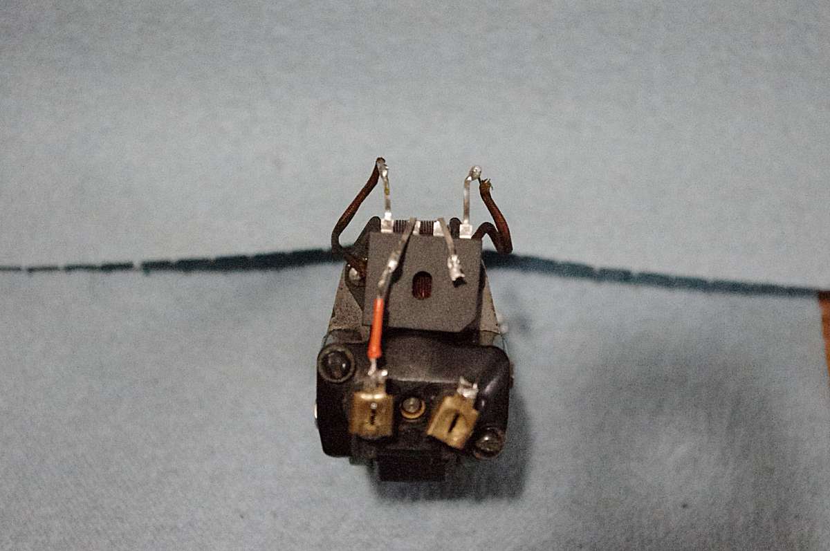
Step 3)
|
|
Step 4)
|
|
|
|
|
Home - Why S - Hirail - Scale - Module - Accessories - About us
Shows & Events - Trade & Sale - Join - Hints & Tips - Members info - Links
| For comments on, change request, or questions send E-Mail Message to the Webmaster All information contained on this site is © 1999 - 2006 Badgerland S Gaugers, unless otherwise credited. The views and opinions expressed in the Badgerland S Gaugers WWW Pages are those of the contributor, unless otherwise credited, and do not necessarily represent that of the club it's officers, directors, or the membership. The Badgerland S Gaugers do not offer any warranties, guarantees, nor assume any liability from the information contained on or referenced from this site. |