


 |
|
![]()
The Franklin locomotive shown in this example exhibited symptoms of erratic performance, hesitation, and stalling. A tap on the tender got it to move a few inches on a track that was supporting other equipment well.
Let's start with
the tools needed.
1) Screwdrivers, both cross point (Phillips) and regular point,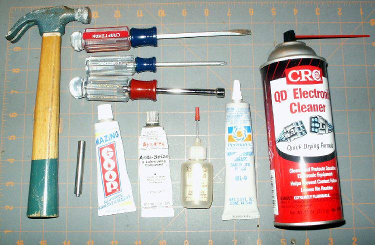
2) Wrench for Driver Screws. Avoid pliers due to scratches and over-torque,
3) Electronic Contact Cleaner, we prefer quick drying formula,
4) White Lithium Grease
5) Plastic compatible lubricating oil for locomotives. Labelle 107 is a good
choice available at most hobby stores
6) Anti-Seize Lubricating Compound found at hardware stores
7) Small tube of adhesive
8) Rivet Driver and Hammer/Anvil. (1/4-20 Bolt or similar size bar stock may suffice)
| Step 1) Starting with disassembly, place the model on your workbench, desk or table to access the top of the loco and the end of the tender. First remove the screw at the rear end of the tender and place where it can be found for reassembly in the original hole it came from. Pick up on the rear of the tender shell about a half inch while holding the rear truck then slide the shell forward about a quarter inch. the metal tab on the front of the frame should disengage with the shell. place the shell out of the workspace to protect it. |
|
| Step 2) Remove the screw at the top of the cab and place it where it can be located for the return to the same hole |
|
| Step 3) Remove the smokestack insert. Use a regular screwdriver capable of fitting into the slots cut in the top of the smokestack and turn counterclockwise like removing a normal screw. The Franklin unit originally had a brass insert although it could have been replaced with a plastic one at some point. Same rules apply. | 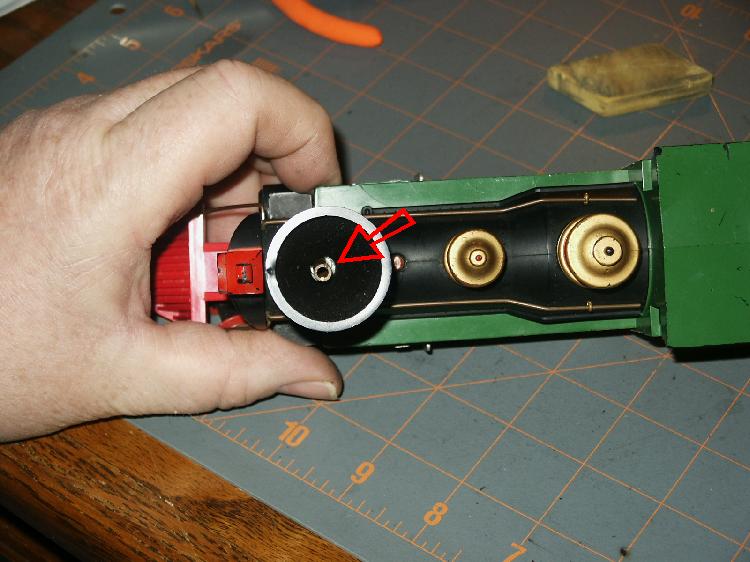 |
| Step 4) Remove the side-rods from the drivers using an appropriate method. Pliers can work for removing the fasteners but the odds are great of scratching the screws and the side rod. A socket type wrench is best for this one. Remove the drive rod from the wheel post and slide the driver with the steam chest rod out of the frame and place it somewhere out of your workspace. Repeat for the other side. Remember which rod came from left and right. They may be bent individually for clearances or you may have to straighten them for necessary clearance. | |
| Step 5) Remove the two screws under the front trucks that hold the chassis in the shell. Place them in a location to remember where they came from | 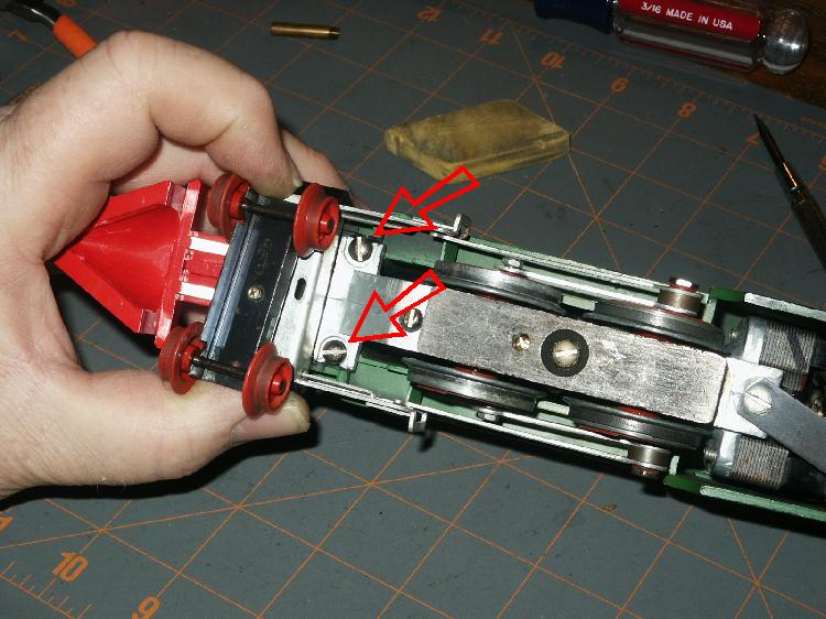 |
| Step 6) Using the contact cleaner OUTSIDE or in a very well ventilated area, clean the areas of the trucks where the axles enter the side-frames and where the pickup strips contact the axles. It appears to be ok to clean the wheels as well. I have not noticed any degradation of material using the fast drying solution. Clean both trucks in the same manner. | 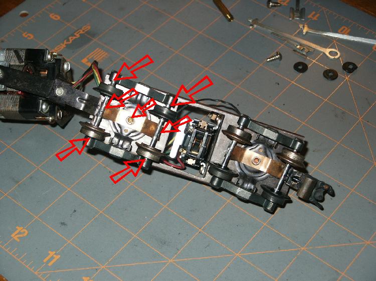 |
| Step 7) Next clean the moving portion of the e-unit. Try to stay away from the coil when spraying the oils off. Generally this is clean from debris, but sometimes people put oil on the mechanism to aid in its function, but the results are short lived and the unit gets sticky refusing to change direction without assistance. Always keep this unit clan and dry. It needs no oil. |  |
| Step 8) Spray clean the front journal and worm drive of the armature to release old oils, fines, and tar buildup from previous years of use. | 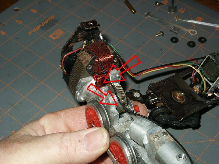 |
| Step 9) Finally, clean the rear journal and commentator. As with the e-unit, try to stay away from the windings. The wires are coated with a shellac and may be susceptible to different kinds of contact cleaner. Better safe than sorry. | 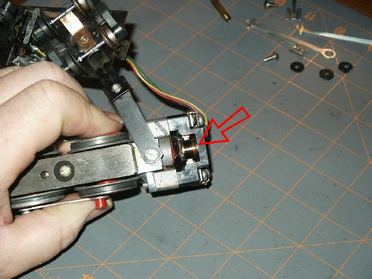 |
| Step 10) In the case of this locomotive, the major reason for the hesitation and requirement for tapping to get it going was due to the spring pickups loose on the rivets. Hold the truck with one hand and swivel the pick-up from side to side to check tightness of rivet. If it moves easily, then the current can not make it through to the wire soldered to the other end. Using a flat punch or a rivet tool, peen the flange over a little tighter. Remember you are working on a delicate electrical unit, not constructing a skyscraper, so tap gently and check for snug movement many times. | 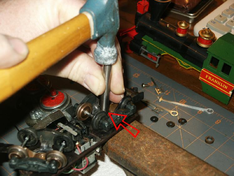 |
| Step 11) Next lets make sure the contact is made between the pick up strip and the axle. When the unit is upside down touch the wheel and push down gently. the strip should be showing pressure on the axle by raising the axle in the side-frames. To regain the tension, hold the end of the strip with one finger while pushing lightly on the spring about 3/8 of an inch from where it bend up. Push a little and check a lot. It is right when the axle picks itself up from the bottom of the holes in the side-frame. Repeat for remaining three strip ends and axles. | 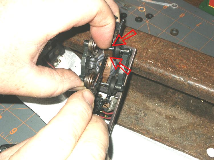 |
| Step 12) Lets talk Oil. Any oil on the motor that is extra will end up inside the engine shell or on the track and wheels of all your moving stock and engines and that is guaranteed. Oil the front armature shaft bushing. Use oil that is approved for plastics. It is a synthetic blend that will not attack the shell. Place a couple drops on the shaft between the thrust washers and the chassis. The oil- lite bushing will absorb some oil due to its porosity and this will maintain lubrication for many hours. No more than 3-4 drops is needed for performance. | 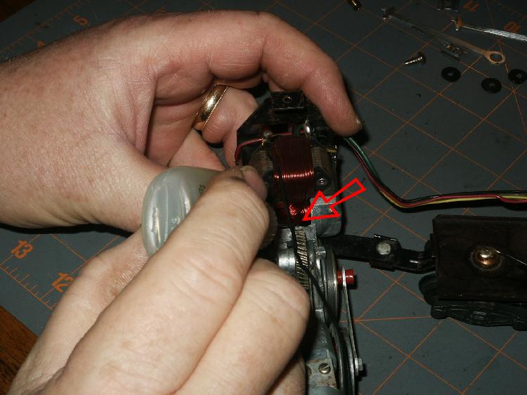 |
| Step 13) Lubricate the brush end of the armature. 2 drops is generally sufficient. Extra oil on this end will cause brushes and commentator to get gummy and carbon up causing issues so keep it lean. | 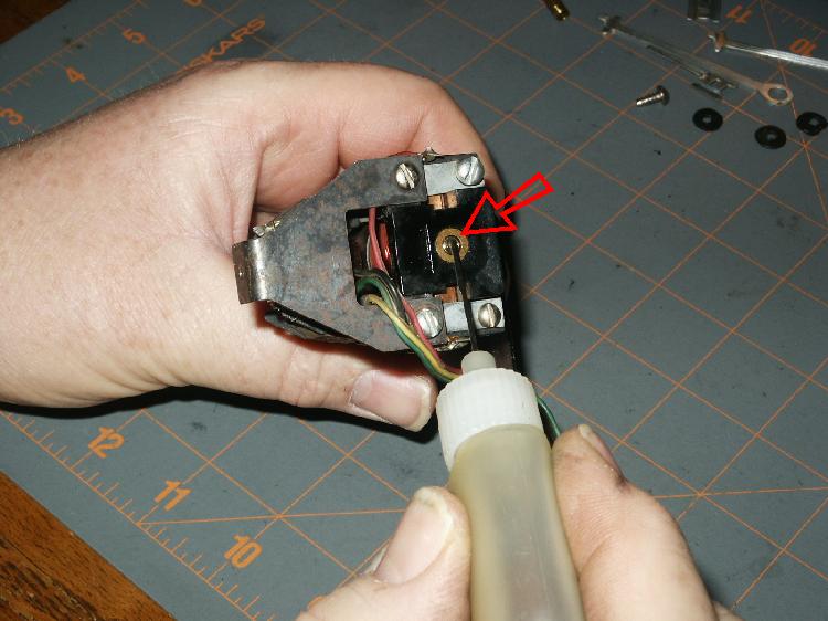 |
| Step 14) Lubricate the gear pin and bolt for the smoke unit arm. A couple of drops is all that is necessary. Do not oil the teeth of the gear or the lithium grease will not stick. It generally is not necessary to oil the other end of the drive rod but it does not hurt anything. extra oil in the chuff chamber where the piston runs will lubricate the sides and reduce the volume of the chuffing sound. | 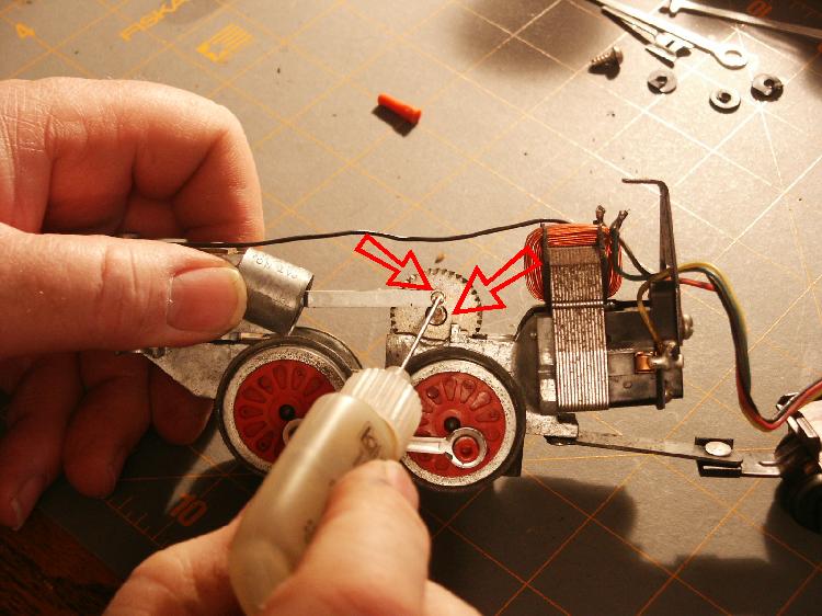 |
| Step 15) A lubricant that I found that works very well for contact on the pick ups is Anti-Seize or sometimes called Never-Seize. It is used in the automotive industry to for applications to threads and pins that you wish to remove at a later time. Anti-Seize is made of Copper Powder, Aluminum Powder, Zinc Oxide, and Graphite. These components are all conductors of electricity and work very well on the pick ups to ensure contact and prevent oils and debris from becoming an insulator. Using a tooth pick place a little on the axle near the copper strip and rotate the wheel set. |  |
| Step 16) White lithium grease or Gear lube at a hobby store is the lubricant of choice for the worm and drive gears. the worm distribute the lubricant during operation between the gears so you only need to put some on the top of the chuff drive gear. spread it out with a tooth pick after adding. | 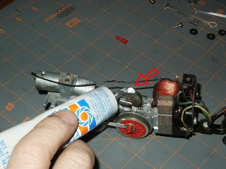 |
| Step 17) Reassembly is next. The Franklin may or may not have rubber washers that insulate the sound between the locomotive shell and the chassis. If yours does use a small drop of general purpose adhesive on the back side of the washer and place it over the hole that it covers. The deformation of the washer should reflect which hole it came from and the adhesive will keep it in place while you assemble the chassis to the shell. Next drop the chassis into the shell lined up to the holes. | |
| Step 18) Reinstall the screws that hold the chassis front in place. Do this with extreme gentleness. This is done by feel and generally is the primary cause in broken screw posts on loco shells. When the plastic gets old it gets brittle. The screw threads MUST find the original threads in the plastic boss made by it from original assembly. Drop the screw into the hole and with a small screwdriver turn gently clockwise. If resistance occurs, do not force it. Turn it counterclockwise until you can feel it drop down a little and try again. Make sure screw is straight. Make only snug. | |
| Step 19) Install the screw in the cab following the same procedure as the chassis. forcing will cross thread the steel bracket and the screw will never tighten up again. | 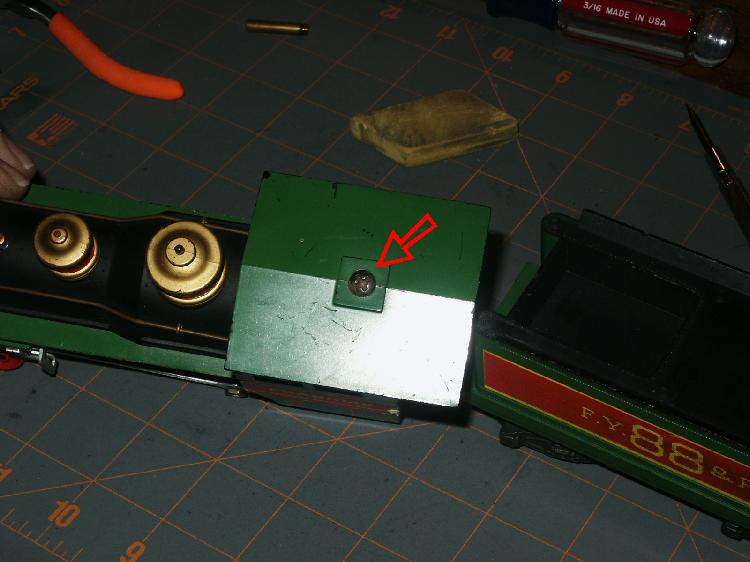 |
| Step 20) Install the brass insert in the smokestack using a screwdriver that captures both sides of the slot. too small will break the slot. Make sure it is straight and it follows the same procedure as the threads above. The insert screws into a fiber plate which can be cross threaded easily as well. General rule of thumb is to feel for resistance ant back it up until it drops a little, then start again. This procedure uses the same feel as picking robin eggs from a nest. Use care and two fingers. | |
| Step 21) Install the rear tender shell by moving the wiring harness off to the right side of the bar that connects the tender to the engine and mating the tab on the front of the tender frame with the slot in the tender shell. The tender frame will slide back into the recess of the lower tender shell and the fastener hole in the frame should line up with the hole in the rear of the tender shell. Use the same care as shown above. There is no "snap in place" situation here and if it is not freely lining up check the wire harness and alignment for binding or the front slot will break in the tender shell under force. Capture the original threads as defined above. |  |
| Step 22) Now that it is all together lets check the trucks to see if they are twisted. Objective is to have all four wheels touching the track on both trucks at the same time all of the time. Place a couple sections of straight track together on your bench and place the locomotive on them. View the spacing at the point where the wheels meet the track as you slowly tilt the tender away from you. Each pair should leave the track at the same time and contact the track at the same time when unit is returned. If they do not touch at the same time the truck is twisted and needs to be straightened. Remove the train, use slight finger pressure by twisting the trucks opposite direction holding both frames of the truck. Do not put twisting pressure on the rivits or you will need to redo Step 10. Twist a little, check a lot. They bend easily. If wheel pair is not touching at all or very little, the side frame may be bent up or other truck frame may be bend down. Repeat on the other truck and the other side. When all four pair touch and move within the frame slots the same amount you are done. Give it a try. If still issues the problem may be in the motor or e-unit with spring pressures or worn or burned brushes. | 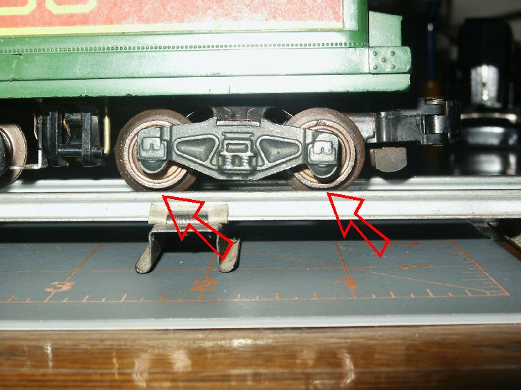 |
Home - Why S - Hirail - Scale - Module - Accessories - About us
Shows & Events - Trade & Sale - Join - Hints & Tips - Members info - Links
| For comments on, change request, or questions send E-Mail Message to the Webmaster All information contained on this site is © 1999 - 2006 Badgerland S Gaugers, unless otherwise credited. The views and opinions expressed in the Badgerland S Gaugers WWW Pages are those of the contributor, unless otherwise credited, and do not necessarily represent that of the club it's officers, directors, or the membership. The Badgerland S Gaugers do not offer any warranties, guarantees, nor assume any liability from the information contained on or referenced from this site. |


