


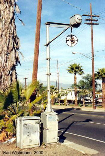
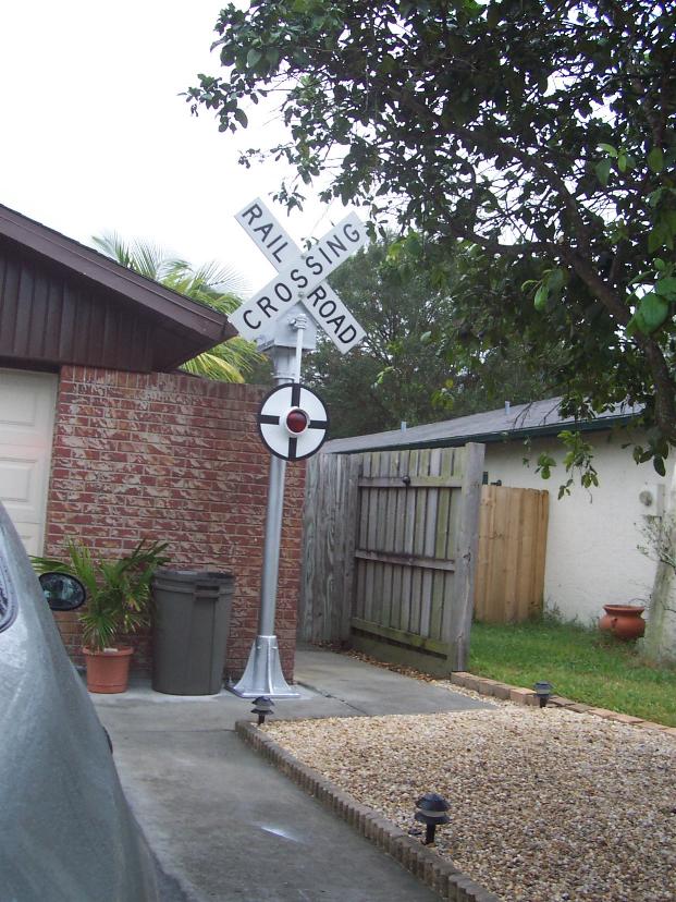
My wig-wag as it stood on 3rd Street in Riverside, CA before
shipping to Florida
(photo by Karl Wichmann)
|
|
|
|
|
|
|
|
|
|
|
|
|
|
|
|
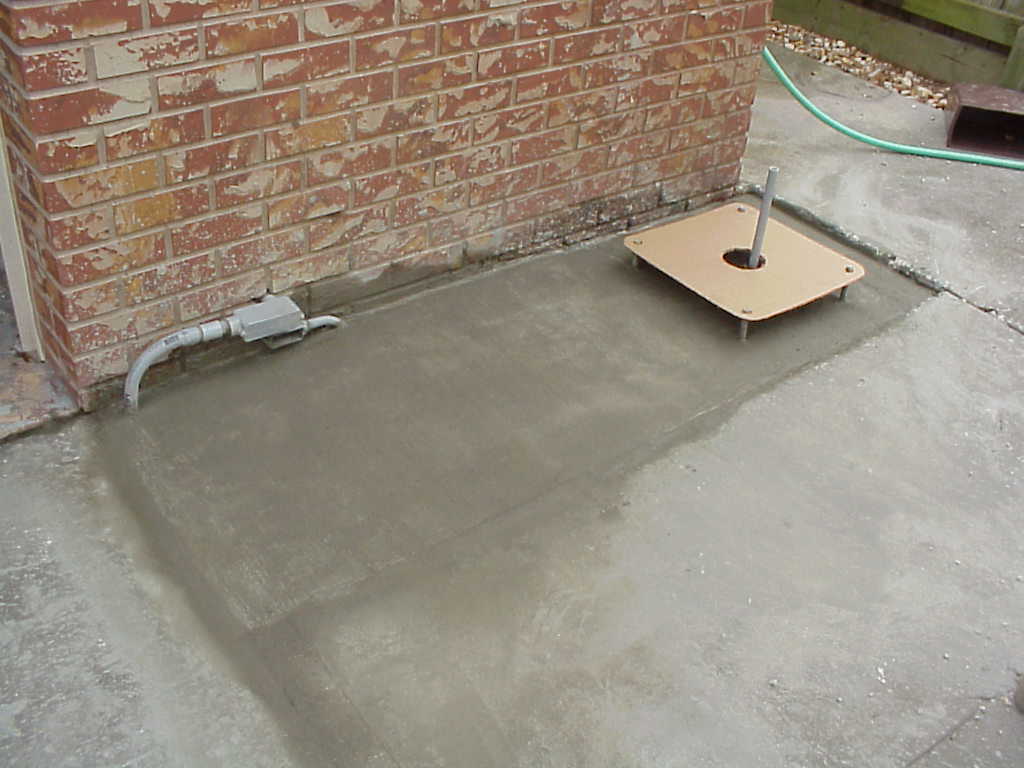
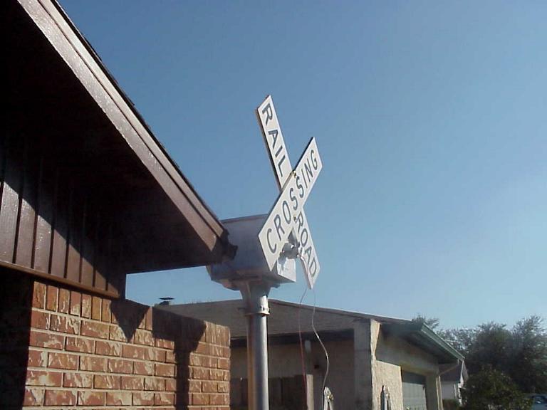
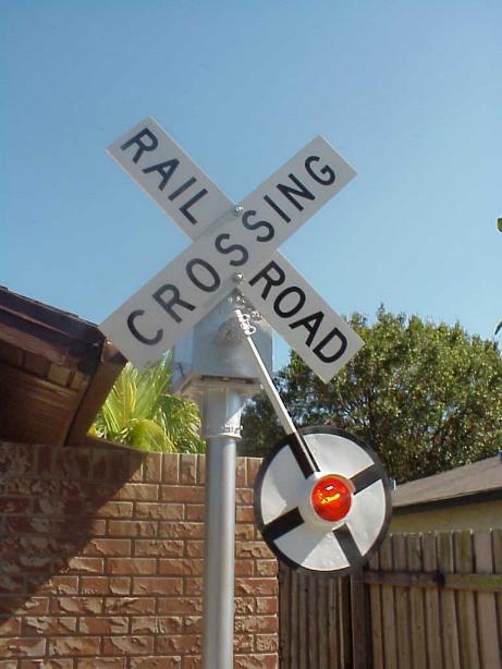
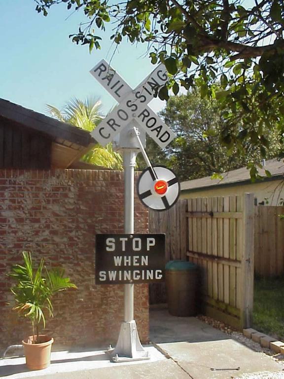
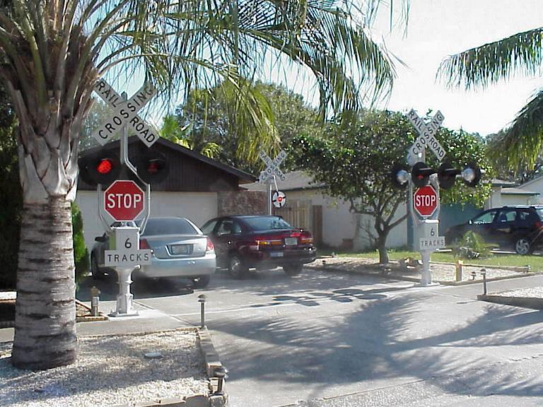
All photos (except noted) by Jerold Crawford (2005)
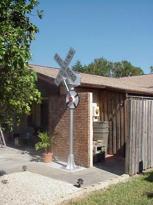
Update - November 2009
|
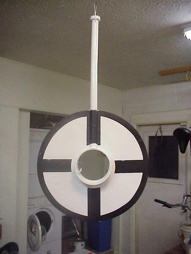
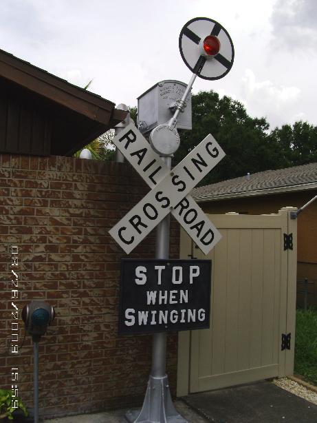
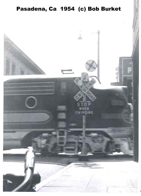
Conversion to an Upper Quadrant Magnetic Flagman
similar to the ATSF signals in Pasadena, CA
I needed to do some work on my first Magnetic Flagman. I was impressed by Bob Burket’s 1954 photo of the Santa Fe UQ signal in Pasadena, CA that I decided to redo this signal in a similar fashion. I purchased a LQ banner from the Los Angeles Junction RR from someone on eBay. I used an extra counterweight to convert it to an UQ style. Just had to drill the appropriate holes and put in a taper pin to let the banner rest on the wig-wag mechanism. Repainted it after having it sandblasted I completely disassembled my wig-was and decided to keep the Van Dyke banner as it was to use on my upcoming Model 10 restoration. I had a cracked terminal block and was able to get another one to replace it. I also changed the movable contact finger and the stationary contacts as well with some reproductions I had purchased.. I also had the coils redipped so they would be better protected from the elements. Lastly, I reinstalled the brake which had been removed from the signal when I got it. When I got finished, it worked better than it ever had. It now operates at 5.5 VDC instead of 9 VDC as it had before. Still fine-tuning some of the tolerances and gaps for optimum performance. |
Express Menu
2/25/04


