 |
||
 |
ERIE
RAILROAD L1 Class - 0-8-8-0 Articulated
American Locomotive
Works by Philip M. Goldstein |
 |
|
ErieL1.info counter added 10 January 2022 |
||
| 20 November 2024: |
Chapters added |
"They
were too big - |
| 12 November 2024: | Firemans Canopy / Shelter profile changed ca. 1915 | Modifications
& Differences |
| 31 October 2024: | Mallet Compounding and Articulated chapters, w/ drawings added | What
is Compounding? Why the need for Articulation? |
| 25 October 2024: | 2600 Christening at ALCo print added | Memorabilia & Photographs |
| 16 August 2024: | 2600 Christening at ALCo postcard added | Memorabilia & Photographs |

.
.
Click on the builders plate ![]() at the bottom of each chapter
to bring you back to this table of contents.
at the bottom of each chapter
to bring you back to this table of contents.
.
.
.
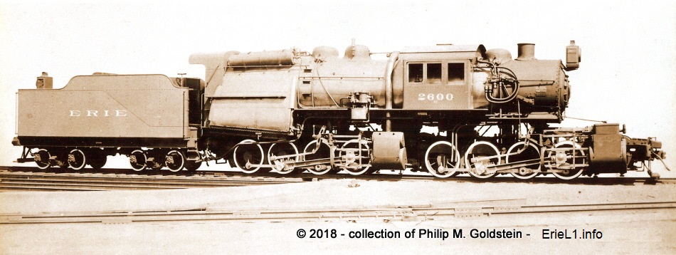
Erie Railroad
- L1 Class #2600
"Angus type" also known as the "Mellin Compound Mallet"
AMERICAN LOCOMOTIVE WORKS
BUILDERS PHOTO - 1907
.
.
.
| road: | Erie | cylinders, low pressure (front): | 39" bore x 28" stroke (simple) | |
| Erie locomotive class: | L1 | cylinders, high pressure (rear): | 25" bore x 28" stroke (Mellin compound) | |
| builder: | American Locomotive Co (Schenectady, NY) | valve type, high pressure: | piston |
|
| builder class: | 0880 C410 | valve type, low pressure: | Richardson balanced slide | |
| date built: | July 1907 | valve gear: | Walschaerts | |
| number in class: | three | boiler diameter : | 84" | |
| Erie road numbers: | 2600, 2601, 2602 | number of tubes: | 404 | |
| construction numbers: | 42269, 42270, 42271 | tube diameter: | 2.25" | |
| wheel arrangement: | 0-8-8-0 (articulated) | tube length: | 21' | |
| driver diameter: | 51" | steam pressure: | 215 p.s.i. | |
| total locomotive wheelbase: | 39' 2" | grate area: | 100 sq. ft. | |
| engine wheelbase (individual): | 14' 3" | firebox area: | 343.2 sq ft | |
| total wheelbase locomotive & tender: | 70' 5" | evaporative heating surface (total): | 5313.7 sq. ft. (5666 sq. ft. after rebuilding) | |
| total length, locomotive & tender: | 84' 9¾" (coupler face to face) | superheating surface: | (1170 sq. ft after rebuilding) | |
| minimum curve radius: | 16 degrees | total heating surface: | 6,108 sq. ft | |
| locomotive weight (on drivers): | 410,000 lbs. | tractive force: | 94,070 lbs. @ 90% cutoff; 89,000lbs. @ 85% cutoff | |
| locomotive weight (total): | 410,000 lbs. (441,660 lbs. after rebuilding) | axle loading: | 54,100 lbs. | |
| tender weight (loaded): | 167,700 lbs. | factor of adhesion: | 4.32 | |
| total weight locomotive & tender: | 577,700 lbs. (609,360 lbs. after rebuilding) | indicated horsepower @ 5.0-6.5 mph: | 800 - 1141 | |
| tender capacity (water): | 8,500 gallons | delivered horsepower @ 5.0-6.5 mph: | 584 - 999 | |
| tender capacity (coal): | 16 tons | date rebuilt: | 1921 | |
| fuel: | soft (bituminous) or hard coal (culm anthracite) | rebuilder: | Baldwin Locomotive Works (Eddystone, PA) | |
| to 2-8-8-2, cab moved
to rear, installation
of: Elasco feedwater heaters, Schmidt superheater Ragonnet Type B Power Reverse Gear Standard "Dupont" automatic stokers Security Sectional Brick Arch |
||||
| all scrapped: December 1930 | ||||
.
My Interest In Camelback Locomotives:
.
Simply put: this website is dedicated to the existence of three very unique locomotives - the Erie L1 Class 0-8-8-0 Articulated Compound Mallets.
I have always had a particular fondness for camelback type locomotives; and of all the wheel arrangements and configurations built, these three articulated mallet types constructed by American Locomotive Works (Schenectady, NY) for the Erie Railroad are at the top of the list. A close second being the St. Clair Tunnel 0-10-0 side tank Camelbacks.
To say that either of these locomotives were unusual, is an understatement.
The Erie L1's were the seventh, eighth and ninth Compound Mallet articulated locomotives constructed in the United States, following the order to American Locomotive company for a single 0-6-6-0 for the Baltimore & Ohio (#2400 "Old Maud") built in May 1904 (ALCo c/n 27478); and an order to Baldwin Locomotive Works for five 2-6-6-2 for the Great Northern. The Mallet concept, as well as articulation; was rather new to the United States, and still in the process of proving its worth.
But the Erie L1's were first and only camelback articulated Mallet locomotives to be constructed in the United States - and for that matter, the world.
The Erie L1's were further noted as "Mellin compound Mallets", after Carl J. Mellin who patented the improved method of compounding the steam cylinders.
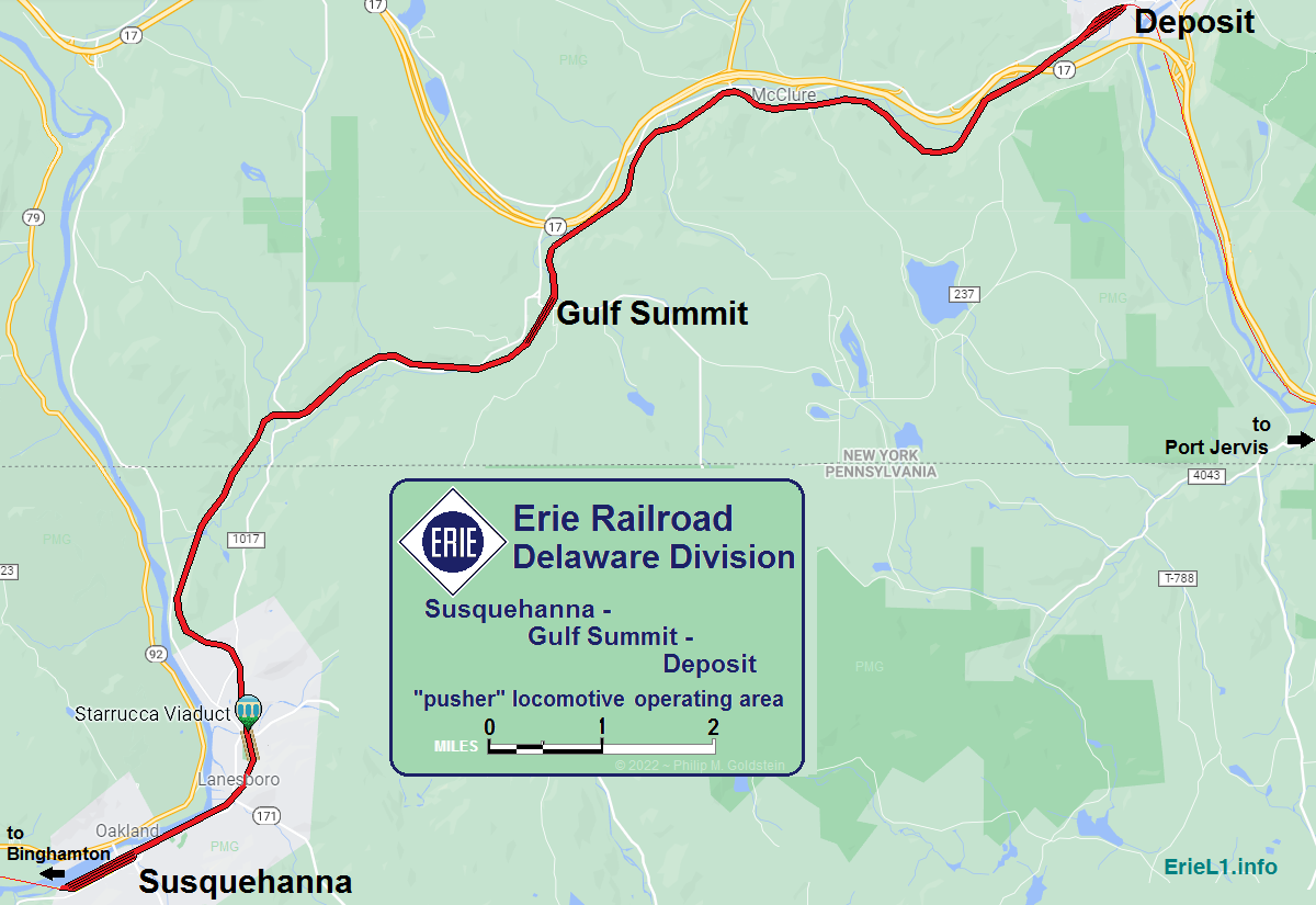
The L1's were designed for and assigned to pusher service over the Gulf Summit grade and Susquehanna Hill, which includes the famed Starrucca Viaduct on the New York - Pennsylvania border, and the line was part of the Erie's Delaware Division.
The L1's pretty much never ventured west of Susquehanna, Pennsylvania; or east of Deposit, New York. However, a publicity image by Erie Railroad shows one of the locomotives in Port Jervis, NY in 1911.
But despite this local limited use, they obviously left their mark on the collective history of railroading as many items were produced to publicize their construction and service; postcards, paintings, and advertising scale models.
These locomotives remain the topic of many discussions today, but unfortunately some of those discussions and comments are rooted myths, misconceptions and misinformation.
So, a great deal of this website is spent in dispelling and proving those myths wrong. That is the premise behind the Real Facts - not Railfan Fiction portion of this website.
As a historian, I am pro-fact and pro-accuracy, and I am as thorough as I can possibly be. I don't merely repeat what I read, I go through the effort of verifying what I read.
"Trust, but verify." Russian proverb
As I gain access to established authoritative
resources, I expand my base of knowledge. I even go out of my way to
collect older technical publications from the 1800's and early 1900's
regarding the subjects I research.
So, a great
deal of the erroneous information that circulates on the internet (and some books) have been proven incorrect on this
website with good old fashioned research,
and posting the
documentation to prove otherwise, hence the Real
Facts - not Railfan Fiction chapters and the 1907 Test and 1908
Thesis chapters showing the
unedited locomotive test results.
Furthermore, it is important to mention that a great deal of the statistics I have stated do not come from crowd-sourced and easily editable Wikipedia; but from established, reputable and authoritative references and sources such as steamlocomotive.com, actual locomotives builders information, as well as industry and technical journals and compendiums from the era the locomotive actually operated.
Since all of the men that actually operated or worked on the Erie L1 are long since gone; some operational information and techniques comes from (and has been corrected) by both active and retired railroaders, especially those with experience in steam locomotive operation.
But unfortunately, due sometimes in part to novice railfans not understanding the technology that existed at that time when compared to todays standards; and sometimes in part to biased opinion; there is an inordinate amount of misunderstanding (or just plain bad assumption) on their parts regarding these Erie locomotives (and to be frank, other topics as well.)
Regrettably, this
erroneous info makes its way onto the web and before you
know it its being parroted in modeling forums, Facebook groups and
railfan
threads.
- "A lie gets half way around the world before the truth has a chance to put its pants on." Winston Churchill
- “The irony of the Information Age is that it has given new respectability to uninformed opinion.” John Lawton
or if you prefer:
.- Damnant quod non intellegunt.
Translation: They condemn what they do not understand.
I have been told I can be long winded, and it's been said I take the long way to get where I'm going, especially when disproving a fallacy.
But it is no longer enough to simply inform someone their information is incorrect, especially so in Facebook Groups, Reddit and internet forums. People now become defensive, obstinate, argumentative, and indignant. Even when I have been polite.
Now, it seems it has become necessary to put all the data in black and white, and literally hammer this time and time again in front of the misinformed, to get them to realize the error of their ways. And sometimes that isn't even enough. As I grow older, I am sorry to say I have lost a lot of patience and diplomacy in dealing with these types. You may be better acquainted with them as the:
.
This is why you will find extensive history and information pertaining to anthracite burning locomotives, what the difference between anthracite and anthracite culm is and so forth.
Because just another "fan page" on a locomotive design and bare basics information might not educate those types.
I know some of you will appreciate the effort.
Naturally, if I am in error; please feel free to contact me and I will make a good faith effort to review the facts you provide.
Regards, and enjoy the website!
Philip M. Goldstein
bedt14@aol.com
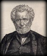 |
Ross Winans |
| October
17, 1796 - April
11, 1877 Vernon Township, New Jersey, USA |
|
In 1828, he developed a friction wheel with outside bearings that established a pattern for future railroad wheels. In the late 1820s, he became associated with the Baltimore & Ohio RR, entering their service as an engineer (designing). His first task was to help Peter Cooper build the revolutionary "Tom Thumb" steam locomotive. In 1831, he would be appointed assistant engineer of machinery on the B&O.In 1835, he went into partnership with G. Gillingham and in 1836, they took over the 1834 lease of the B&O Company's shops at Mount Clare and continued the manufacturing of locomotives and railroad machinery. In 1841 however, he opened his own shop adjacent to the Mt. Clare Shops. Winans was a pioneer in the development of coal-burning steam locomotives, including the use of anthracite coal; and substituting it for the less efficient wood-burners of the era. Winans set trends in locomotive and car design rather than followed them. His steam locomotives, popularly known as "Crabs," "Muddiggers," and "Camels"; were used all over the expanding Northeast U.S. rail network. From 1843 to 1863; Winans delivered approximately three hundred locomotives to twenty-six different American railroads. He is also credited with being the first US locomotive manufacturer to export a locomotive to Europe. The B&O was Winans' largest locomotive customer, with 140 locomotive deliveries going to that railroad alone. Winans' second best customer was the Philadelphia and Reading Railroad. These two customers represented 70 percent of Winans' total sales. James Millholland, master mechanic of the Cumberland & Pennsylvania RR (and then Philadelphia & Reading), worked with Winans on Cooper's "Tom Thumb", and was quite familiar with keeping these "Camel" engines running, and making improvements to them. Winans' customer relations were simple—he built engines his way, and you bought them. While he was eccentric, his locomotive business made him independently wealthy. Bored with the business, and having a design disagreement with the B. & O., he closed his shops and pursued other endeavors. |
|
|
|
|
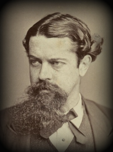 |
Zerah Colburn |
| January
13, 1832 - April 26, 1875 Saratoga, New York, USA |
|
Colburn was the nephew of his namesake, Zerah Colburn, a noted prodigy in advanced arithmetic. With no formal schooling, Colburn was a teenage prodigy in engineering. Barely in his teens at the start of the railroad boom, he found work in Lowell, Massachusetts as an apprentice in the "drafting room" of the Lowell Machine Shops. Colburn had a career of breakneck speed. He was a restless man, quick of brain and also quick of temper. He would fall into jobs and fell in with people; but repeatedly fell out with them too; but as he moved about the various locomotive works of New England, he gained experience as well as an eye for engineering detail. He also produced his first book, "The Throttle Lever". Designed as an introduction to the steam locomotive, this became the standard U.S. textbook on building locomotives. The book took Colburn, then not even 20 years old, deeper into the world of publishing, but it also earned him the wider respect of railroad men across America – both locomotive builders and train operators. Colburn worked or was associated with a number of locomotive works between 1854 and 1858, including: Baldwin Locomotive Works; Tredegar Locomotive Works at Richmond, Virginia; Rogers Locomotive Works; and the New Jersey Locomotive and Machine Company. While at NJL&M, Colburn began construction of the "Lehigh" for the Delaware, Lackawanna & Western RR in February 1855. It was of the 0‑6‑0 type, with an overhanging firebox of 7' 6" in width. The first such use of the wide firebox for anthracite. Colburn's intention was to use a firebox six feet long, but he left the New Jersey Locomotive Works in a disagreement and before the "Lehigh" was completed, and the builders reduced the length to 4' 6. The locomotive proved a poor steamer, and the firebox was subsequently lengthened to six feet, as proposed by Colburn. Ultimately; overwork, an addiction to laudanum, alcohol and poor financial management took their toll on his mental health. In trying to ease his mind; he became increasingly delighted by London prostitutes whose pleasures he much enjoyed, but where he contracted syphilis. Colburn, sensing the impending shame offered by Fleet Street journalists and their diligence to seek out and publish the "truth", he became depressed and reckless, leading to his return to the U.S. – where he found himself disowned by his wife and daughter, of which led to his eventual suicide at the mere age of 38. |
|
|
|
|
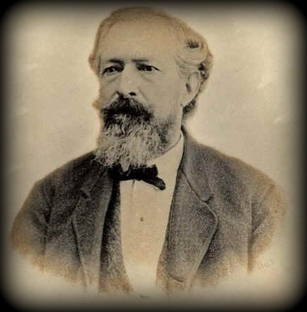 |
James Millholland |
| October
6, 1812 - August 1875 Baltimore, Maryland, USA |
|
Millholland had the honor of working on Peter Cooper's "Tom Thumb" locomotive (along with Ross Winans), and found so much pleasure in working with it, he dedicated his profession to railroad locomotives. Railway master mechanic for the Philadelphia & Reading; and designer of the anthracite firebox for that railroad (and in separate but parallel development with Colburn); as well as many other inventions, which became standard on American railroads. Also an early user and advocate of the superheater, the feedwater heater, and the injector. Inventions and contributions include the cast-iron crank axle, wooden spring, plate girder bridge, poppet throttle, initial design of the anthracite firebox, water grate, drop frame, and steel tires. |
|
|
|
|
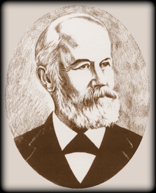 |
John E. Wootten |
| December 23, 1822 -
December 16, 1898 Philadelphia, Pennsylvania, USA |
|
Wootten would assume Millholland's position of master mechanic; when the latter resigned from the P & R. While James Millholland first designed a firebox for burning anthracite; it would be Wootten that would go on to perfect the final result for burning anthracite culm, and have his name inextricably associated with the design. Wootten also realized in the mid-1870s, when he held the position of Superintendent of Motive Power (and soon after General Manager) of the Philadelphia & Reading RR; that if a firebox be could be designed to utilize the vast unwanted quantities of anthracite culm (mine / breaker waste) in the Northeast United States; a vast savings in the cost of operation of steam locomotives could be achieved. Due to its width and placement, the design of the Wootten firebox required the repositioning of the engineers cab which resulting in the Camelback locomotive type. This is without a doubt the most significant part of the Erie L1 design, not to mention all those Camelback style locomotives that both preceded and succeeded it. |
|
|
|
|
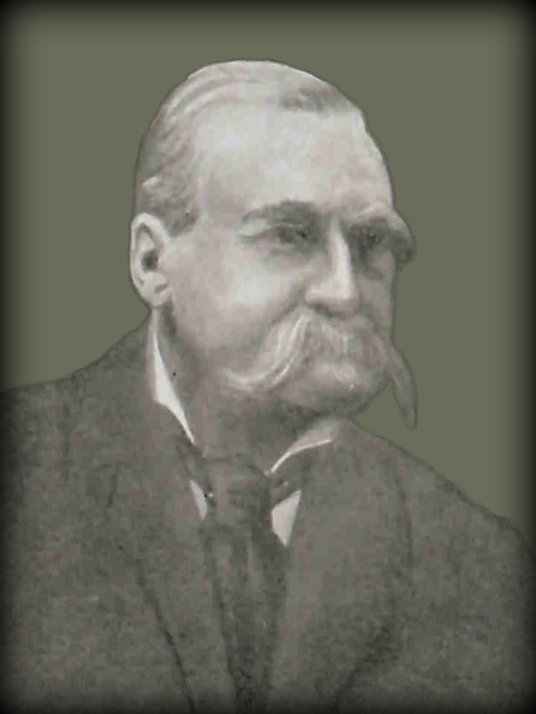 |
Anatole Mallet (pronounced mal-LAY - rhymes with ballet) |
| 1837 - October 1919 Lancy, Switzerland |
|
Mechanical engineer, inventor of the first successful compound system with articulated railway steam locomotive, patented in 1874. He developed the boiler over articulated frames containing drive wheels and compound cylinder placement (in contrast to the Beyer or Garrett types of articulated locomotives); and of which the Erie L1 fell into this Articulated Mallet design type. This Mallet style of locomotive became popular not only for the heavy freight drag or pusher operations; but for timberland harvesting firms with excessive curvature and steep grades as well. |
|
|
|
|
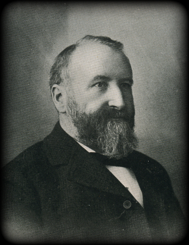 |
Angus Sinclair |
| 1841- January 1, 1919 Laurence-kirk, Mearns, Forfar, Scotland |
|
Erie Railroad special instructor, locomotive engineering, publisher of "Railway & Locomotive Engineering" technical journal and the "Development of the Locomotive Engine", one of, if not the most comprehensive history on the construction of locomotives. Sinclair was respected by all designers and master mechanics, no matter which railroad they worked for. Sinclair's "contribution" to the Erie L1, was that he is believed to have stated before the L1's were completed, that the L1 would "dry up the country's canals and make water transportation obsolete". While this was clearly hyperbole, it is understood that the Erie RR saw fit to honor this statement by assigning Sinclairs' name to the class of locomotive: "Angus" |
|
|
|
|
|
While all the men mentioned thus far have contributed to the advancement of steam locomotives, or at least certain design philosophies; it is this man that is most directly and specifically involved in the design and construction of the Erie L1 Articulated Compound Locomotives: |
|
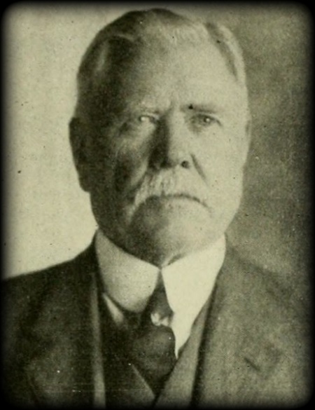 |
Carl J. Mellin |
| February
17, 1851 - October 15, 1924 parish of Hagelberg; Skaraborg County; Västergötland region, Sweden |
|
Mechanical engineer and designer of steam locomotive and marine steam propulsion systems. From 1877 to 1887, after completing technical studies, apprenticeships and internships; he was employed by Robert Napier & Son, Glasgow, Scotland; as a designer for maritime propulsion systems, as well as the ships themselves. He then was employed by Atlas (now Atlas Copco) in Stockholm, Sweden. He immigrated to the United States in 1887. In 1894, he obtained the position of chief engineer for the Richmond Locomotive Works, in Virginia; and in 1902 began employment as a consulting engineer for American Locomotive Works of Schenectady, New York. Here, Mellin directed the design office as well as supervised the workshops for the construction of propulsion machinery for US Navy battleships; but his forte was designing locomotives. He is recognized for the designing the "The Spirit of the Twentieth Century", a 4-4-2 "Atlantic" built for the "Big Four" (the Cleveland, Cincinnati, Chicago and St. Louis Railway) exhibit in the Palace of Transportation at 1904 Worlds Fair / Louisiana Purchase Exposition in St. Louis, Missouri. This exhibit earned him a gold medal. Specific to this website, Mellin was supervising engineer for American Locomotive Company when the Erie L1's were designed and built, and he developed and patented the specific compound cylinder system used on the Erie L1 design. |
|
(No, they weren't the same thing.)
- That's Wootten, with two O's and two T's;
- Camels vs. Camelbacks,
and- Anthracite vs. Anthracite Culm
Some readers may not know the reason for the cab astride the boiler arrangement of Camelback locomotives, so it is here that I will take some time to explain. It is quite lengthy so be forewarned.
First, it bears mentioning that there were two distinct types of steam locomotives that had center mounted cabs. They are often interchangeably called camels and camelbacks, but this is incorrect; each type were specific to their own design.
The original "Camel" type locomotives were built by Ross Winan, a prolific railroad inventor of the era. First built in 1848; these "Camel" locomotives were designed to burn anthracite coal appropriately sized for locomotive use; not anthracite culm. These locomotives were designed as slow speed, heavy haul freight locomotives and all were originally of the 0-8-0 wheel arrangement. Over 200 were produced.
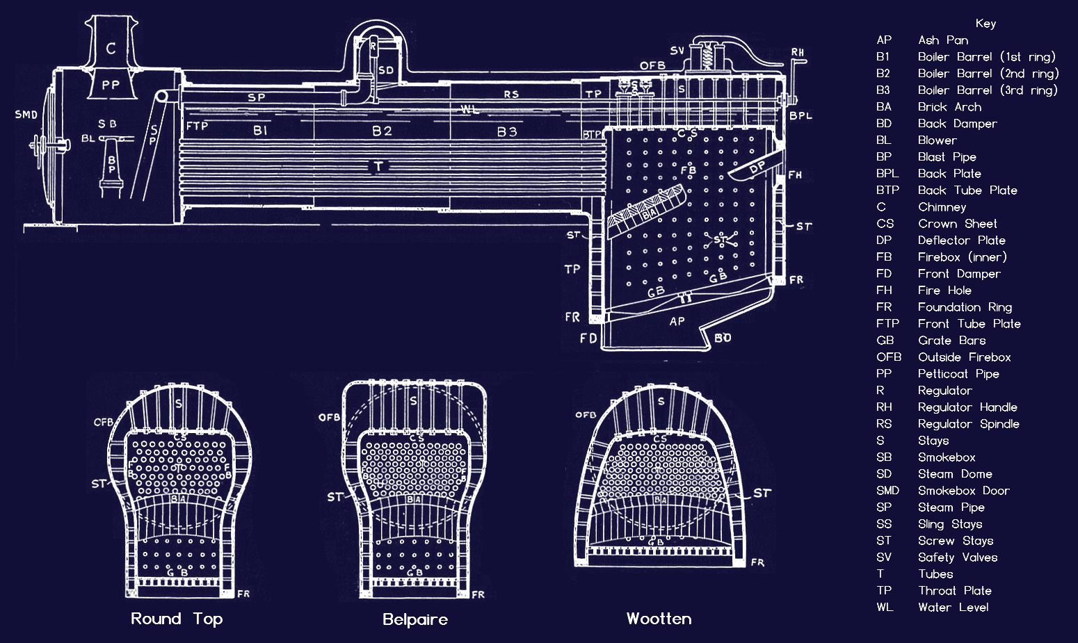
The outer perimeter of the firebox was contained completely between the wheels and over the axles. They had sloped top fireboxes further defined by a loading chute on top of the firebox in which to feed coal. Originally, coal was fed from a elevated platform on the tender, and not from the tender deck; but this was later modified and the use of fire doors on the rear became standard.
So successful was the locomotive, that the design was copy-catted by several builders as well as subsequently improved upon by Samuel Hayes, Master of Machinery at Mount Clare Shops of B&O RR; and by Matthias Baldwin of Baldwin Locomotive Works, among others. Even the Altoona Shops of the Pennsylvania RR rebuilt at least one Winan's Camel.
As these locomotives were rebuilt, other wheel arrangements (namely 2-6-0 and 4-6-0) were adapted to the Camel design. Nevertheless, it is this design of locomotive and this design only that should be referred to as "Camels", and are seen below left.
Camelback or "Mother Hubbard" locomotives had firebox doors on the rear, a firebox that extended over and wider than the wheels, and the boiler went through the cab, not under it. They were designed to burn anthracite culm.

..
2.2:
Anthracite vs. Anthracite Culm
Before commencing with the next chapter; it is imperative for the reader to understand that at this juncture, firebox development was designed to use screened or sized anthracite; not anthracite culm, which was small, and irregularly sized waste.
Unfortunately, many contemporary railfan websites and discussions co-mingle the words "anthracite" and "culm" when discussing it as a fuel; but which in fact were very different from one another. While they both come from the same type of coal; it was screened (sized) anthracite that was used first in locomotives, and of which was produced by the coal mill or "breaker" and sorted by size using metal screens of various sizes.
Anthracite, is a type of coal. It has the highest content of carbon, and less impurities of the other types of coal: bituminous, sub-bituminous, lignite and peat. It burns cleanly and produces little smoke, and is the hardest of all the coals, therefore it takes longer to ignite and burn. Because it has the highest amount of carbon, it burns the hottest. Anthracite is prevalent in the Northeastern Pennsylvania region.
Culm waste, was the leftovers after breaking & sizing raw anthracite; as well as coal that had already been screened and sized but fractured as it was being handled and progressed down the chutes, it fell through the screens to the bottom of the breaker house and transported to the culm piles.
Here is an analogy: think of lumber;
.
2.3: Screened (or Sized) Anthracite
When it came to the early steam locomotives, they burned screened anthracite, not culm waste.
Screened coal (of any type) are sizes of coal that were able to pass or not pass through a specific sized sorting screen and constituted a maximum dimension. A large piece of coal would pass over the screen, which coal that fit through the sized opening would fall through.
The most commonly used sizes of screened anthracite coal for locomotives was "grate" (also known as "broken"); or "egg" which was the next size smaller.
It should be emphasized
that smaller sizes of coal under "egg", which are comprised of the following sizes (in diminishing order) of which were used for:
"stove" and
"chestnut" for domestic household stoves and heating:
Smaller sizes of coal such as: "pea", "buckwheat" and "rice" and "barley" (not shown); were used for industrial applications such as automatic stoker furnaces used for power generation and for use in electric arc furnaces to produce foamy slag.
Also not listed or show below is larger sized "steamboat" (4½" to 6") which was used for steamships. This size was not preferred for locomotive use neither.
|
|
|
| Coal Trade - 1920 |
sizes of screened coal: 12" tile, US
quarters: 15/16" diameter steamboat, rice and barley sizes not shown. |
.
.2.4: Parallel Development for the Anthracite Burner
|
According to Angus Sinclair's "Development of the Steam
Locomotive", 1907; there were a multitude of attempts to burn hard coal
in locomotives by locomotive designers and master mechanics. Each of these locomotive designers carried their own individual beliefs into what would work and why "the other guys design didn't work", but they all had one thing in common, and that was their desire to burn anthracite. While several of the designs produced never made it to widespread acceptance or production; some in part to their genuinely being unsuccessful from a technical or operational standpoint. Yet other designs did. But there was another reason why some designs did not find widespread acceptance. The following statement by Henry F. Colvin as quoted in Sinclair's book, and of which struck a chord with me:
So apparently, even if the locomotive performed acceptably; it was still subject to prejudice from "old timers" that turned their nose up at it. How little has changed in society, and how we continue to this day to pooh-pooh new ideas, designs, and ways of "doing things." Some of the designs that saw success sprung from the minds of Ross Winans, Zerah Colburn, and James Millholland. |
|
James Millholland became involved with the railroads at an early age, with the honor of working as an apprentice on Peter Cooper's "Tom Thumb" locomotive; which was the first American built locomotive to operate in the US and on a common carrier railroad.
Millholland had found so much pleasure in working with that one locomotive, that he dedicated his profession to railroad locomotives. He progressed his way up through the ranks of the mechanical forces until he eventually attained the position of railway master mechanic for the Philadelphia & Reading Railroad.
At this point in time, most locomotives were primarily fueled with wood or soft coal: bituminous, which was also available in Pennsylvania and neighboring West Virginia. It was here that Millholland realized, due to the plentiful supply of anthracite coal located in Northeast Pennsylvania; that he attempted to design a firebox capable of burning this plentiful but hard coal. Anthracite was so hard in fact, it was also called "stone coal".
Millholland would take wood burning locomotives that were either at or nearing the end of their service life, or had suffered various forms of firebox or boiler failure; and rebuild them with fireboxes of his designs.
Millholland's final design found that a wider and shorter firebox than normal was needed to burn this anthracite. As anthracite coal is harder than bituminous (soft) coal and by taking longer to burn, locomotives using anthracite therefore needed more "grate area" to sufficiently "fire" (generate steam) in the locomotive.
A simple comparison would be to wood species used for heating: softwoods such as pine or fir burned fast; while hardwoods such as maple, oak and ash burned slow.
Typical wood or bituminous (soft coal) burning fireboxes on locomotives of that time were long and narrow, and fit between the locomotive frame. Because anthracite burned slower, more was needed on the grate to produce enough heat to evaporate water to make steam. In stationary or very large objects like factory boilers and ship boilers, there was all the room that could be had for larger grates. But on locomotives it was a different story - they were small by comparison.
Millholland found if the firebox was enlarged and made wider (instead of long and narrow), anthracite could be burned in a mobile object such as railroad locomotives.
His plans were interrupted in January 1854, when the Philadelphia & Reading Shops burned, and his attention was needed on the rebuilding of those facilities. While he was eventually able to return his attention to converting the P & R's fleet of locomotives to coal burning; he never truly succeeded in developing a successful anthracite firebox. He eventually resigned his position in 1866. His successor would be one John E. Wootten.
.
2.6 - John E. Wootten & Using Anthracite Culm
John Wootten began his locomotive apprenticeship at the Baldwin Locomotive Works in 1837. He left Baldwin Locomotive in 1845 to join a small shop operated by the Philadelphia & Reading Railroad.
Over the course of his career, he was appointed to Engineer
of
Machinery on February 1, 1866 when Millholland resigned; then he
advanced to Assistant Superintendent and Engineer
of Machinery
on February 2, 1871. On January 15, 1873 we was appointed to the
position of General Superintendent, and finally to General Manager on
January 10, 1877.
Like Millholland prior to him, Wootten was aware of the
plentiful amount of anthracite from the areas mines.
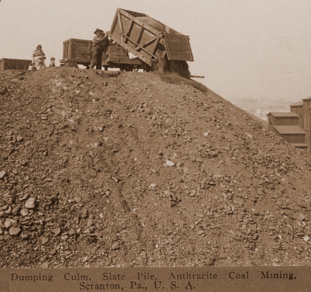 |
But even more prolific, was
anthracite waste or
"culm". Culm is the granular remnants and smaller pieces of coal after it had been broken and sized by screening for commercial use. As this culm was mostly small and irregularly sized, it was unwanted and contained up to 15% of foreign matter: slate, stone, sand, etc. Waste culm accounted for 18 to 20% of the production of anthracite coal for commercial use. And without a salable use, this culm found itself being piled next to or in close proximity to the breakers (the coal sizing mills) and in quantities to be considered a nuisance. As with most things unwanted, it was extremely cheap and in large abundance. In "large abundance" might very well be an understatement, as there were hundreds of veritable mountains of this unwanted culm scattered throughout Northeastern Pennsylvania. |
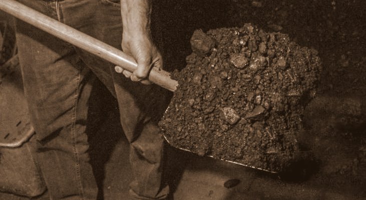 Anthracite Culm
|
.
2.7 - How Cheap was Culm?
Putting it into perspective for the era: circa 1890; the rates for coal was as follows: screened anthracite coal of the pea size cost 60 cents per gross ton, whereas anthracite culm was only 10 cents per gross ton.
This constituted a 50 cent per ton difference; however it should be noted that the pea anthracite and the culm was blended 1:1 for use in Erie locomotives. This brings the averaged amount to 35 cents a ton, allowing for a net savings of 25 cents per ton of coal. Other railroads used a blend of bituminous and anthracite culm. And when you have hundreds of locomotives burning hundreds to thousands of tons of coal a day; in using the culm, the cents add up into dollars.
Also, it should be known that culm to be used for locomotives was not used directly from the coal tip.
Culm was first washed to remove sand, shale and other small debris inherent from mining. But even with this washing step, it was still much more economical to use anthracite culm rather than the commercially sized coal that came from the production run.
.
2.8: Trial and Error and then Having to Break Old Habits
Culm consisted of sizes smaller than "buckwheat" coal, including "rice" "barley" & "pea"; with a small allowance for powders as well as larger sizes.
One of the issues that Wootten encountered in using culm as a locomotive fuel was by its being small and light, it would become airborne and lofted through the high draft fireboxes that were commonplace of that time for burning wood or larger chunks of anthracite coal. Or it would fall through the grates with wider openings that were used for that same wood or bituminous coal and wind up in the ash pan.
Thus Wootten began using a finer grate (smaller and thinner openings), and less (or softer) draft through the firebox. This combination had the effect of leaving the culm on the grate to burn completely; and when it did, the culm burned evenly and well.
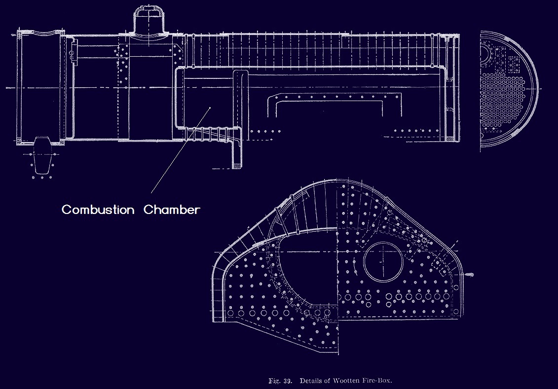
The addition of a combustion chamber between the firebox and the flue sheet, furthered more complete combustion, allowing for greater heat transfer for increased efficiency and reducing soot and fuel wastage.
Yet, as soon as he had those problems solved, another issue cropped up. As the locomotive left the roundhouse and started working, the fire struggled.
The firemen of that time were used to piling the wood or larger chunks of coal thickly on the grates, which by nature of their size had ample space around the chunks for air to circulate through. This is also known as a "deep bed";
That method may have worked well for those large sizes of coal or wood as the voids around the fuel allowed air to filter through, but it did not work for anthracite culm.
Here is an analogy: think of a road made of rock and another road made of dirt. Here the gravel represents large sized anthracite, and the dirt represents culm, and water represents air. Water will drain through the rock because of the void spaces around the rocks; but puddles form on the dirt road, because the water has nowhere to drain to.
Well, Wootten learned the firemen were piling the anthracite culm into thick beds. Not enough air could rise through the bed of culm to support combustion and essentially they were smothering the fire or starving it. They took the air out of the fuel + air + heat equation or "fire triangle".
In their defense, this is what the firemen of that day had been trained for and used to. They were not used to any other methods.
.
2.9: Success = Large Grate Area, Thin Bed of Coals with Short Flame, Minimal Draft, Lower Brick Arch and a Combustion Chamber
|
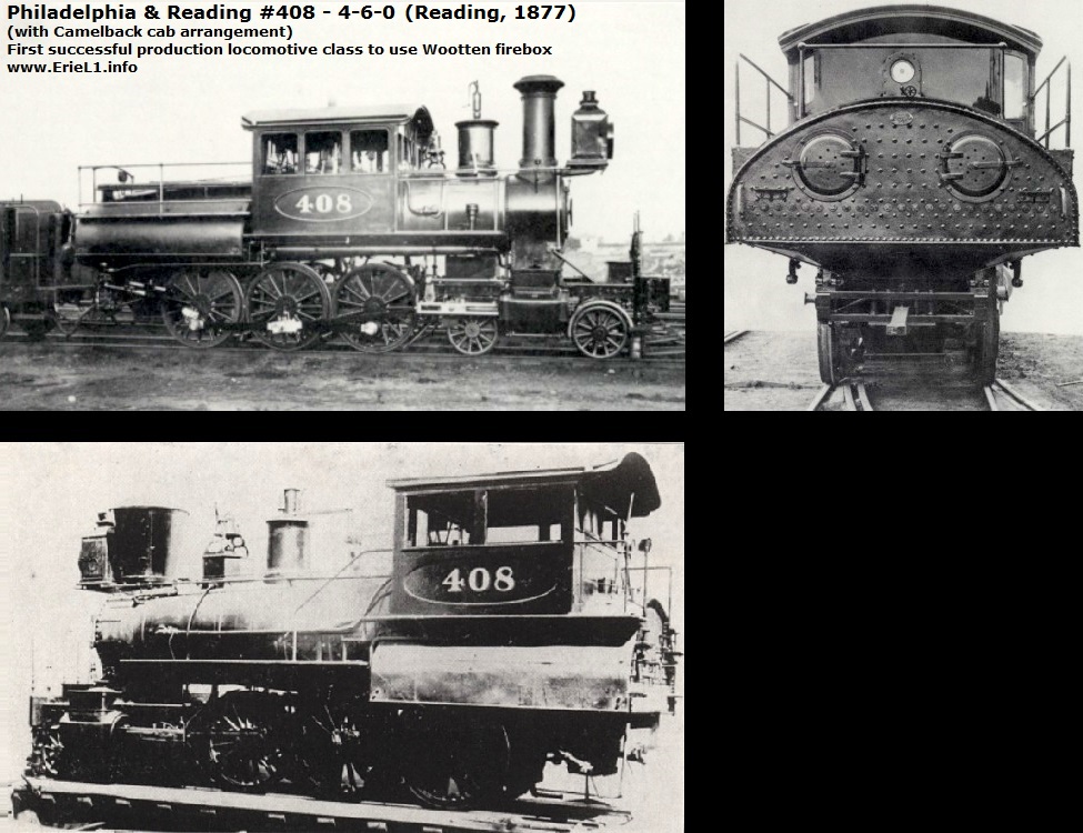
By dispensing with the previously established practices of firing by that method, and now specifying to the firemen that a thin bed of fuel and short flame; Wootten was able to make his firebox design meet the criteria required of being reliable, efficient, easy to maintain and as such; the heat output steady. And with these instructions, even a novice fireman could maintain it. And so in 1877, the firebox design fitted to P&R #408, and the new found firing practices meant Wootten had found the answer. In other words; anthracite culm / waste was now a suitable fuel for locomotives, where men of varying degrees of ability could satisfactorily achieve and maintain the fire fueled by culm, for producing a steady and reliable production of steam for all operating conditions; whether it flat and level or mountainous territory; the slow pulling of a heavy freight; or a fast paced running of a passenger train on a tight schedule. This new "fuel" equated into a savings of $2000 per locomotive per year. And in 1883, the Philadelphia & Reading rostered 171 locomotives with the Wootten firebox. That equaled $378,000 per annum in saved fuel costs. Obviously, the corporate higher ups and the shareholders were pleased. The Wootten firebox also changed the weight distribution on the locomotive chassis, and due to the increased size of the firebox, meant the firebox needed to be mounted as far over the rearmost driving wheels as possible for support; and to avoid Colburn's issue of a excessively long drawbar connecting the engine and tender. This (mostly) precluded the use of trailing trucks on the frame to support the firebox with smaller diameter wheels common to freight service; but it increased tractive effort as more weight was directly on the drive wheels. |
 |
So revolutionary was the design, that sister locomotive P&R #412 was shipped overseas to be demonstrated. The locomotive won the silver medal at the Exposition Universalle de 1878 (Paris, France); after demonstrating throughout Europe and proving successful.
The Wootten firebox design also was awarded the following medals: the John Scott medal (bronze) awarded by the City of Philadelphia and by recommendation of the Franklin Institute; and in 1883, the Philadelphia & Reading won an award for "best locomotive meeting important new principals" by the National Exposition of Railway Appliances, held in Chicago, Illinois.
At the end of 1895, there were about 800 locomotives in service with Wootten's firebox design. By 1925, there were approximately 3,500 to 4,000 locomotives in service with Wootten's firebox.
.
2.10: Both Sides of the Coin
There was another positive attribute to be said for Wootten's firebox design: it burned bituminous coal equally as well as anthracite.
When the price of anthracite and with it culm, rose due to both growing popularity as well as due to coal miners strikes; the railroads began using either a bituminous / anthracite culm blend, or straight bituminous.
Obviously, because bituminous burned faster, not so much coal was needed on the grates, so grate boxes or frames were fabricated which reduced the grate firing area confining the coal to the centered middle of the firebox.
Bituminous fireboxes however, because of their smaller square footage of grate area; could not be fired on anthracite or anthracite culm.
2.11: But Not Everyone was Happy
But, this oversized "Wootten" firebox took up most if not all of the space on the rear of the boiler or "backhead" where the cab was normally placed. This position of the firebox also presented the issue of the cab floor now being higher than the standard tender deck height.
 |
Also, due
to the broad nature of the firebox, the engineer could not see around
the firebox as he would encounter with a normal rear mounted cab. If the cab were to be mounted on top of the Wootten firebox, the crew would be in effect sitting on top of the firebox. Also as a result of this placement, the cab would be raised higher than before, and would necessitate that some of the tunnels of that time to be raised. This of course was not an option. As we can see by the bottom left image, the Philadelphia & Reading even contemplated this rear cab Wootten firebox arrangement. Ungainly to say the least! So, necessity dictated the locomotive cab be located towards the center of the boiler in front of the firebox instead of on the rear as normal; sort of like a horse's saddle. Hence the modern "camelback" locomotive was born. This placement of the cab allowed the engineer to retain access to the entire length of the boiler, and likewise from the front or the rear steps to maintain the appliances and bearings. The fireman would remain to the rear of the firebox to feed the fuel as customary, and tenders with high deck heights were constructed for use with camelback locomotives. With the engineer in the cab to operate the locomotive; this would mean the engineer and the fireman would be out of instant communication with one another. This would be one of the serious concerns brought about by opponents of the camelbacks. At first, these were old timers set in their ways. In some cases, a speaking tube (like those used on ships) would be answer. |
.
2.12 - A Trailing Truck - To Be or Not To Be?
As mentioned, the weight of the large firebox box and resultant weight distribution of the locomotive required the firebox to be placed over as much of the driving wheels as possible.
And with the smaller diameter wheels common to freight locomotives, is why Camelbacks are predominantly seen in wheel arrangements without trailing trucks, and where the rear driving wheels could carry the full weight of the Wootten firebox.
These wheel arrangements were mostly comprised of (but not limited to) those listed:
And, there were road engines as well, such as:
Exceptions to this rule of course, were high drivered - high speed passenger locomotives such as:
.
2.13 - Whyte Notation
also called the "wheel arrangement"
In the United States and United Kingdom, wheel arrangements of locomotives are described by the leading or pony wheels (in any), the powered drive wheels and the trailing truck (in any).
This system was devised by Frederick M. Whyte, and came into use in the early Twentieth Century. Geared steam locomotives, electric locomotives as well as diesel electric and gasoline mechanical locomotives do not use the Whyte notation. These are classified by their model and the number of axles and trucks, and whether those axles are powered or unpowered.
The Whyte Notation counts from left to right (with left being the front of the locomotive); the number of idle leading wheels (not the axles as in other systems), then the number of powered driving wheels, and finally the number of idle trailing wheels, with these numbers being separated by hyphens.
For example, a locomotive with four wheels (on two axles) leading in front, then six driving wheels (on three axles) and then two wheels (one axle) trailing is classified as a 4-6-2 locomotive, and is commonly known as a "Pacific".
A small switching locomotive with no leading wheels, (four driving wheels on two axles), and no trailing wheels, is notated as an 0-4-0.
With this system being explained and returning to camelback locomotive design.
.2.14 - Camelbacks: Who Used Them?
Returning to camelback locomotive design, as a result of this large firebox on the rear of the locomotive, the cab was relocated to middle of the boiler and such locomotives became known as "Camelbacks" or "Mother Hubbards".
The camelback design worked very well for many of the railroads located in the Northeastern United States that either operated their lines through the "hard coal country" of Pennsylvania, or those that received coal from Pennsylvania for local coal suppliers.
There were many and by no means should this be considered a complete list:
|
|
- Union Pacific
- Southern Pacific
- Santa Fe
- Canadian Pacific
|
When
locomotive design practice evolved to accommodate rear mounted cabs on
locomotives with Wootten fireboxes, these cabs lacked the usual doors
on
the front wall. This is perfectly illustrated by the image
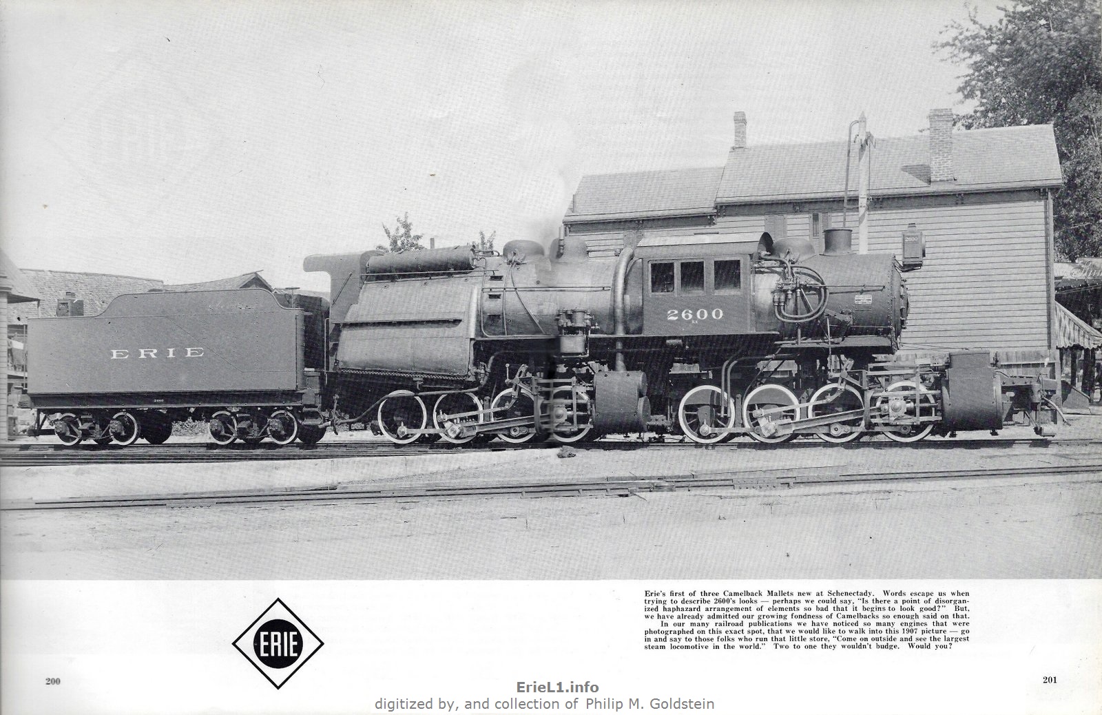
of the rebuilt Erie L1 at right. Without a doubt, this lack of front doors on the cab hindered the engineer and / or fireman from their basic maintenance duties such as but not limited to: filling the sand domes; adjusting valves; cleaning the bell; oiling and maintaining the steam generator for locomotive lighting; all of which are along the top of the locomotive as well as lubricating / maintaining the air pumps for the brakes, which were mounted along the side of the locomotive. The engineer or fireman (or both) would have to climb down at the rear cab / tender access steps, walk to the front of the locomotive, then climb back up to boiler walkway; instead of exiting directly from the front of the cab as had been the practice. |
Erie Railroad #2600
after Baldwin rebuild - 1921
authors collection |
And you thought the engineer sat on his seat and the fireman leaned on his shovel all day!
It should be noted - this trend away from camelbacks was due in part to safety. But as I will cover in a later chapter, camelbacks were not universally banned by the Interstate Commerce Commission or any other federal agency, by locomotive employees unions, et cetera; despite the popular misconception they have been.
Then if the camelbacks weren't outlawed, what did cause the trend away from camelback type locomotive design? What usually talks the loudest? Money!
Just as in the beginning when anthracite was cheaper than bituminous and culm was the cheapest of anthracite, anthracite rose in price due to its desirability of being clean burning and low dust; which made it a favorable fuel for home heating. This led anthracite coal breakers to be more judicious in what they dumped as culm (waste), as well as the resulting increased prices from increased demand.
Added to this increase in the price of anthracite, was the Anthracite Coal Miners strike of May - October 1902.
That led locomotive manufacturers to revert to firebox designs that burned the now cheaper bituminous coal that did in camelbacks. And as stated previously; a Wootten firebox is just as capable and efficient at burning bituminous coal as it could culm, so existing locomotives with Wootten fireboxes could run either.
This is to say nothing of the development of the diesel-electric locomotive in the 1930's; first as switchers, then in increasing quantities of road locomotives; which pretty much supplanted steam as a locomotive power on the whole by the 1950's.
.
2.16 - Crew
Comfort in Comparison to Another Type of "Camelback"
And the following comparison might be somewhat of a stretch, but the camelback locomotive would not be the only widely successful locomotive design where performance and reliability was exceptional, but its shortcomings were crew ergonomics or comfort. What locomotive is this you ask?
|
None other than the
Pennsylvania Railroad GG1. Another center cab design, it could
in a way, be considered a "camelback electric
locomotive". Access to the locomotive cab was via a rather tall vertical climb. And once inside, both the engineers and firemans stations were notably cramped. There was a small passageway connecting the two sides, but with floor to ceiling banks of controls and gauges, it made it visually difficult to see from one side to the other from either station. I can personally say I have been in the cab of a GG1. Even though I'm 5' 9" (and not very svelte), it would a very tight squeeze for even someone of smaller stature. Then there is all that electrical energy being converted from AC to DC, the transformers, and traction motors; it all gave off heat. Add to this the presence of an oil fired steam boiler in the cab which was used to generate steam heat for the passenger cars. No doubt it made for some uncomfortable crew conditions, especially on long distance trips. But undoubtedly, the GG1's were in fact a successful locomotive design and many were built. There were thousands of center-cab diesel locomotives built (especially by General Electric) so having the cab located in or towards the center of the locomotive, so the center placed cab was not a disqualifying factor in and of itself. |
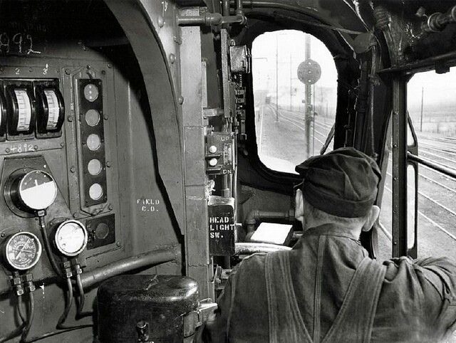 |
Again, as I and others have pointed out, despite the outcry over steam powered camelbacks, they were in fact; successful as well.
.
Chapter 3:
What is Mallet Compounding?
|
The three Erie L1 0-8-8-0 locomotives were the only
articulated Mallet Camelbacks
built, and they would also have the distinction of being the Erie
Railroads' first
"Mallet"
locomotive, as well as their first articulated locomotive. For the record, the correct pronunciation is mal-LAY, after Anatole Mallet, who was a Swiss mechanical engineer and consultant. However, and all too frequently here in the States, it is often pronounced mal-LUTT (like the hammer). You may say ta-MAY-to, I may say toe-MAH-toe; but mal-LAY is the correct pronunciation in this case. Mallet Compounding is a system designed to utilize steam twice, instead of once (also known as simple expansion). Compounding thereby extracts additional energy or force out of steam, making the engine more efficient. Therefore in such an engine that steam from a boiler is used first in high pressure (hp) cylinders, then piped partially expanded to a second set of low pressure (lp) cylinders for final expansion. Compound: |
|
This compounding method is a very efficient way to use the steam twice for large multi-cylinder locomotives, as well as marine vessels and stationary steam locomotives used for electrical generation or pumping; and where single expansion would have used up the steam capacity too quickly.
.
3.1 - The Intercepting Valve
But there was another feature inherent to the design of Mallet Compounding; the intercepting valve.
This valve, located in the left side high pressure cylinder, allowed the engineer to admit high pressure steam into the low pressure system. This was especially useful when starting the locomotive and train on a grade. Not often, but when required; a train may have had to stop while already on the the incline. If the train was heavy enough, even an L1 could have issues getting moving again with all that tonnage. By admitting high pressure steam into the low pressure system, gave the front cylinders more power, and having more power assisted in getting the train started moving again.
But, there was a drawback to using this intercepting valve: in its "simple" setting where it diverted high pressure steam to the low pressure cylinders, it used up the steam pressure in the boiler at a quicker rate.
Therefore
it only was used absolutely when needed, and was not
intended to be used in
normal operation. Westing referencing to this in the Erie Power
book (as you will read later).
"The
L1's could operate as simple or single expansion locomotives, if
desired, by use of an intercepting valve. This was a feature on Mallets
and arranged for live, or high-pressure steam to be fed to all
cylinders, thereby, increasing tractive force considerably. On
the
other hand it had the effect of speedily draining the boiler of
steam"...
Westing clearly states simple expansion was an option "if
desired".. Nowhere does he state that it operated in this simple
expansion mode all the time.
Unfortunately, most railfans only read the second half of the chapter. Perhaps Westing could have worded it better, but it is still very clear that when read carefully and thoroughly, the boiler was only "speedily drained" in the simple expansion mode of the intercepting valve, not all the time during regular compound operation.
And this effect was known long before the L1's. It is inherent to the design of the Compound Mallet with intercepting valves. (For the record, a Compound Mallet could be built without an intercepting valve, and it would be useful in a normal capacity just the same.
Where I will pick apart Westing's description: "live, or high pressure steam". Live steam is under pressure, any pressure; whether it be 215 psi or 50 psi or 5 psi. Under any pressure, it is "live" steam. Only once it is exhausted and not under pressure, is it considered "dead" steam.
You can have a 1 hp single cylinder steam engine that operates at 5 psi.. like the little alcohol powered novelty toy engines that are sold. If steam is under pressure, it's live steam. It's still alive partially expanded from 215 to 50 psi. Only when fully expanded and no longer under pressure, is it dead. Like electricity: any voltage in a wire is live voltage. Zero voltage is dead.
So, he should have stated "live, or pressurized steam". Other than that, and quite obviously, this Mallet Compounding design was successful, as these L1 locomotives served not only the Erie Railroad reliably for 23 years for but before then, as well as after; on many other articulated Mallet compound locomotives that were built for several different railroads.
.
3.2 - Articulated ≠ Compounding
It should be kept in mind that an articulated locomotive does not equate to Mallet Compounding. Articulated denotes the type of frame or chassis, and from that you had Simple Articulated or Mallet Compounding Articulated.
As such, not all articulated steam locomotives need be of the Mallet Compound type. A significant number of articulated locomotives were built were of the simple expansion type. And plenty of rigid frame locomotives utilized compounding, but were not of the Mallet Compounding design.
Commencing in the late 1920's, saw the advent of successful, high efficiency superheating, feedwater heating, improved metallurgy and manufacturing practices for higher boiler pressures, mechanical coal stokers, etc; which led locomotive builders away from the compound Mallet locomotive design, but the design did not become extinct.
The Chesapeake & Ohio Railway ordered twenty-five H-6 class 2-6-6-2 in 1940 for use as low-speed coal mine shuttles between the mines and classification railyard in Russell, Kentucky. Ten locomotives were completed before the order was cancelled with the final locomotive delivered in 1949. It is these ten locomotives that would carry the distinction of being the last compound Mallets constructed.
If any class of service to which type was better suited at than the other; compound Mallets seemed to be preferred for low speed, heavy drags and pushing; whilst simple expansion types were predominantly used for higher speeds over longer distances; but this is not set in stone.
A short, very incomplete list of the popularly known types of articulated locomotives, both Mallet compound and simple:
| Mallet (Compound) Locomotives |
Simple Expansion Locomotives |
||||||||
| year built | railroad | class | wheel arrangement | notes | year built | railroad | class | wheel arrangement | |
| 1904 | Baltimore
& Ohio |
2400
"Old Maud" |
0-6-6-0 |
first Mallet Articulated | 1910 | Southern Pacific | MC-2, MC-4, MC-6 | 2-8-8-2 | |
| 1907 | Erie | L1 | 0-8-8-0 | 1936 | Norfolk & Western | A | 2-6-6-4 | ||
| 1910 | Norfolk & Western | Y | 2-8-8-2 | 1936 | Union Pacific | CSA-1/2; 4664 "Challenger" | 4-6-6-4 | ||
| 1912 | Pennsylvania | CC1 | 0-8-8-0 | 1941 | Duluth, Missabe & Iron Range | M-3 / M-4 | 2-8-8-4 | ||
| 1918 | Virginian | AE | 2-10-10-2 | 1941 | Union Pacific | 4000 "Big Boy" | 4-8-8-4 | ||
| 1940 | Chesapeake & Ohio | H-6 | 2-6-6-2 | last Mallets built | |||||
Chapter 4:
Why the need for Articulation?
"It
don't mean a thing, if you ain't got that swing - doo wah - doo wah -
doo wah!"
.
4.1 - What is Articulation?
|
An articulated locomotive is a steam locomotive with an engine unit that can move independently of the main frame. The purpose of articulated locomotives was to provide additional drive wheels (which in turn added tractive effort), but avoid the drawbacks of the lengthening the wheel base as would on a rigid frame locomotive; of which would limit the locations the locomotive could be operated at, that being track profiles with sharp curvature, whether they be mainlines or mountain logging railways. More axles meant a longer wheel base, which equated to the shallower curve that particular locomotive could be operated on. The most axles ever incorporated into a single rigid frame in US locomotive design, was the 9000 class 4-12-2 for the Union Pacific Railroad. The most axles incorporated into an articulated locomotive set, is four: 0-8-8-0, 2-8-8-2 and 4-8-8-4, as well as the 2-8-8-8-2 and 2-8-8-8-4 triplexes. Another benefit of the articulating locomotive, is that it allowed one large locomotive to replace multiple smaller locomotives, which would have also meant their needing a separate engineer and fireman for each locomotive. A single articulating locomotive also eliminated the associated cost for maintenance and upkeep of those multiple locomotives. The articulated locomotive is designed to allow the front set of driving wheels and its mechanisms be mounted to a frame that pivots or "swings" to the left and right (on the horizontal plane), separately and independently from wheels and machinery on the main frame. On an articulated locomotive, each group of these drive wheels with their cylinders, drive rods and other associated components; is called an "engine". Therefore, articulated locomotives have a front engine and a rear engine. In the case of the triplexes; there was a front, a middle and a rear engine. So, by dividing up the axles into two groups (or even three groups as done on the Erie & Virginian Triplexes) allowed the locomotive to be operated on sharper curves than a single long rigid frame locomotive could. This was especially useful where numerous curves existed along a rail line; such as those encountered on mountainous territory like the Erie, or on logging operations in the Pacific Northwest. |
|
leading or pony truck - powered drive wheels - powered drive wheels - trailing truck
As such is the case of the Erie Triplex, those were 2-8-8-8-2: a two wheel lead or "pony" truck, three engines of eight drive wheels, and a two wheel trailing truck; or in the case of the Virginian Triplex 2-8-8-8-4, denotes two wheel leading truck, three engines of eight drive wheels and a four wheel trailing truck
By comparison, those Whyte notation examples of rigid wheelbase locomotives such as the 0-4-0 through the 4-12-2; the single center number represents the powered drive wheels.
The following table represents the wheel arrangements of known standard gauge articulated (simple and compound) locomotives built and operated in the United States.
| Whyte Notation | Whyte Name | user railroads |
| 0-4-4-0 | D&RGW | |
| 2-4-4-2 | "Little River" |
Columbia River Belt Line |
| 0-6-6-0 | "Two six-coupled" | B&O, KCS, WM, NYC, WM |
| 2-6-6-0 | "Denver & Salt Lake" | D&SL |
| 2-6-8-0 | GN, AGS, B&O | |
| 2-6-6-2 | "Mallet Mogul" | GN, C&O, WM, NdeM |
| 2-6-6-4 | "H4-A" also "Norfolk & Western" | N&W, P&WV, SAL, B&O |
| 2-6-6-6 | "Allegheny" | C&O, VGN |
| 4-6-6-2 | "Cab Forward" | SP |
| 4-6-6-4 | "Challenger" | UP, Clinchfield, NP, D&H, D&RGW, SP&S, WM, WP |
| 0-8-8-0 | "Angus" | Erie, PRR, NYC |
| 2-8-8-0 | "Consolidation Mallet" or "Bull Moose" | PRR, GN, UP, RDG, B&O, KCS, AT&SF |
| 2-8-8-2 | "Chesapeake" | N&W, SP, UP, OR&N, Southern, VGN, GN, Clinchfield, D&RGW, RDG, WM, MP, SL&SF, DM&IR, PRR |
| 2-8-8-4 | "Yellowstone" | NP, SP, DM&IR, D&RGW |
| 4-8-8-2 | "Cab Forward" | SP |
| 4-8-8-4 | "Big Boy" (originally Wasatch) | UP |
| 2-10-10-2 | "Virginian" "3000 class" | AT&SF, VGN |
| 2-8-8-8-2 | "Triplex" | Erie |
| 2-8-8-8-4 | "Triplex" | VGN |
abbreviations: AGS = Alabama Great Southern; AT&SF = Atchison, Topeka & Santa Fe; B&O = Baltimore & Ohio; C&O = Chesapeake & Ohio; D&H = Delaware & Hudson DM&IR = Duluth, Missabe & Iron Range; D&RGW = Denver, Rio Grande & Western; D&SL = Denver & Salt Lake; GN = Great Northern; KCS = Kansas City southern: MP = Missouri Pacific; NdeM = Nuevo de Mexico; NP = Northern Pacific; N&W = Norfolk & Western; NYC = New York Central; OR&N = Oregon Railway & Navigation; PRR = Pennsylvania RR; P&WV = Pittsburgh & West Virginia; RDG = Reading; SAL = Seaboard Air Lines; SL&SF = St Louis & San Francisco SP = Southern Pacific; UP = Union Pacific; VGN = Virginian; WM = Western Maryland; WP = Western Pacific |
||
Before concluding this chapter, it should also be taken into account that some rigid frame duplex locomotives, like the 4-4-4-4, 4-6-4-4, 4-4-6-4 or 6-4-4-6; while they have two groups of drive wheels and two sets of cylinders similar to an articulated locomotive, they were not articulated, and consisted of a single rigid frame containing both sets of drive wheels.
.
| The L1's were designed from the very beginning for, and
assigned to "pusher service"; that is, they
assisted by pushing heavy freight trains over Gulf Summit on the
Pennsylvania / New York border. The Gulf Summit was not simply straight up and over, it had numerous curves and reverse curves on both sides of the summit. These freight trains normally had one or two locomotives on the head end; which was sufficient for most of the route, which was fairly level along the banks of the Susquehanna River and the West Branch of the Delaware River. But to go over the steep Gulf Summit, those two locomotives were inadequate. While placing a third or even fourth locomotive at the head end of the train would provide more pulling power, but with the weight of the train pulling backwards downhill due to gravity, the train could then incur a pulled draft gear (the bar that holds the coupler under the freight car) or a broken coupler knuckle. This would make the train "break" into two parts, and even with the recent advent of air brakes, this was not something a railroad wanted to happen on steep grades. Pusher locomotives were therefore added to the rear of the trains if needed at Susquehanna, PA for the eastward trains; and at Deposit, NY for westbound trains to push them up and over Gulf Summit. Pushing relieved the tension and strain on the draft gear and coupler knuckles throughout the train length, as well as alleviated slack action which is also known as run in / run out. |
 |
and the P1 Class Triplex "Matt H. Shay" for direct comparison
.
We were fortunate that a very nice history concerning the construction and reconstruction of these locomotives is contained in the 1970 book: "Erie Power" by Fred Westing & Alvin Staufer (Staufer Publishing, 1970). You will find these pages under the chapter of Erie Mallets, pages 198 through 215.
For the sake of thoroughness, I have scanned and reproduced the pages here on the chapter of Erie Mallets for reference. I highly recommended purchasing a copy of the book, if for nothing else, the great action photographs. The book can be found for very reasonable amounts on most used book websites, internet auctions and shopping sites.
Until my own research, and for the longest time; I pretty much regarded this historical accounting as gospel - and many others did as well. After all, it was published 50 some odd years ago and within a generation or two of the locomotives operation. There also was not much available open source to the average railfan to dispute.
.
6.1 - Unfortunately, it contains some inaccuracies and indistinct statements
However, as original documents and photographs surfaced during my research, I uncovered several discrepancies and / or indistinct statements; some major, others merely cosmetic.
Insomuch, learning of these inaccuracies was kind of disappointing, as I have always revered the older publications (like the Staufer "Power" books) to be the last word and authoritative.
It now appears that in his composition, Mr. Westing may have allowed a little too much personal opinion sway his judgment on overall performance or in captions for the images. In particular are his conclusions regarding the performance testing conducted by the Erie Railroad and Cornell University in 1907, and of which the explanations for some of the lackluster results.
The test results are defined in great detail, and explain the reasons behind the results of the "third" test, and how it skewed and lowered the average performance numbers on the whole. These explanations can be read in The Erie Test - 1907 and the Cullen / Gridley - Cornell U Thesis - 1908 chapters later in this website.
I have also included the last few pages of that chapter which pertain to the experimental Erie 2-6-8-0 Mallet and the Erie Triplex 2-8-8-8-2 "Matt H. Shay", and as the images of the Erie L1 both as built and as reconstructed by Baldwin Locomotive Works were on those pages, even though the text was for a different locomotive entirely.
I have annotated the scanned pages with those differences I found or highlighted details that reinforce my disproving of common myth and misinformation.
Please note, the following pages have been digitized for reader convenience, reference and review under the Fair Use provision of the US Copyright Office and no such infringement should be inferred by the use of said documents for commentary, criticism, and research as discussed below. Original copyright remains with original author (Frederick Westing) and publisher (Alvin Staufer / Staufer Publishing).
|
|
|
| . | |
|
.
.. |
|
|
|
|
1) "two fire doors to facilitate spreading coal" and; "if you wanted to use two fireman" |
3) dynamometer car rated to 70,000 lbs tractive force, but the L1's were rated at 94,000 lbs.! |
| . | |
|
|
|
| . | |
|
|
The wooden pushing beams were installed from the beginning. They are seen in the erecting drawings, builders photographs (including the E. DeGolyer construction image on p.202 above) as well as images in Railroad Gazette (p.174). |
| . | |
|
|
|
While this highlighted text has nothing to do with the Erie L1 Class; it does show how misinformed present day railfans assume that when the coal and water was used up in the Triplex, it lost tractive effort. Which as read here, was not the case as it clearly states that factor was taken into account in the design! Not to mention the locomotive being used on short runs and replenished more quickly, the coal and water was not run down as other distance hauling locomotives would be. |
|
| . | |
|
|
|
| . |
Table of comparative statistics among the various Erie Mallets (L1 class highlighted). |
| . | |
|
|
|
| . | |
|
|
|
|
"Erie Power" |
|
| .. . . . |
|
Camelback locomotives already have erroneous information swirling about them. The Erie L1 class Mallets appear to be doubly damned in regards to misinformation.
Not only do a lot of railfans not understand how they worked, but also do not understand what they were designed for and the work they performed; why only three were built; and when they were designed, they were cutting edge technology of that era.
It is all too easy for todays generation of railroad enthusiasts to look at the culmination of super-power steam locomotives of the 1940's through 1950's; and then erroneously think these Erie L1's weren't good enough, simply by comparison to those latter designs.
Some of these misconceptions arise from the Staufer / Westing chapter of Erie Mallets in "Erie Power"; while others come from present day misunderstandings and myths posted in Facebook Groups by the misinformed; or worse, the less-than-minimally informed. You know the types: "If I didn't see it, it didn't happen" juxtaposed by the "I read it on the internet, it must be true!" types.
"The Erie 0-8-8-0 wasn't the biggest - the 'Big Boy' was."
"World's Largest Locomotive"In early 2024, I received an email from a railfan, stating the Erie L1 wasn't the largest locomotive ever built - it was the Union Pacific's "Big Boy". The tone of correspondence was rather indignant, I may add.
First, I had to take a minute and re-read his email to make sure I was not misreading it. When I realized I had not; the next few moments I took were to come out of a state of shock over the tone of indignancy. Only then, could I take a few minutes to actually explain the "Big Boy" wasn't built until 1941, and these L1's were built in 1907, and when they were built 34 years before the "Big Boy"; the L1's were the largest steam locomotive built - at that time.
And even then, if you were take all the steam power built up to 1954 (the year the last steam locomotive was built for general service in the United States); the "Big Boys" were still not the undisputed "largest" by several units of measurement. referencing the page: "The Largest Steam Locomotives" on steamlocomotive.com website:
.
Needless to say, despite my reply; I am still awaiting a response from this person (but I'm not holding my breath...)
There are those that will counter with that the C&O M1 was not a true steam locomotive, it was a steam turbine; as was the N&W "Jawn Henry". But both were coal fired, had boilers and ran on steam. The PRR S2 was a steam turbine locomotive, and no one ever questions whether or not that was a steam locomotive.
I am not anti-"Big Boy" or anti-Union Pacific in the least; nor can I say with honestly that I favor eastern railroads over western; pre-superpower designs over superpower; experimental locomotives vs. those commercially produced and sold, etc. I am not an Erie Railroad historian or even an Erie "buff", nor can I consider the Erie my "favorite" railroad. That honor belongs to the rail-marine operations of the Brooklyn Eastern District Terminal.
But, I can say very enthusiastically that the Erie L1 is my favorite locomotive design.
An analogy would be like a "car guy" trying to compare a 1920's Model T to a 1950 Cadillac. Of course the Caddy was bigger, more powerful, much faster, heavier, could go further, and do so more comfortably! Yeah, they both had four wheels and ran on gasoline, but that is about where the similarities end. Hell, one shouldn't even compare a Model 'T' to a Model 'A' for that matter because of the advancements made in automobiles in that 20 year period.
As of her restoration to operation in 2019, the Union Pacific 4014 "Big Boy" is the largest steam locomotive currently in operation in the United States.
But she is not by any means, the largest steam locomotive "ever built" and certainly not before 1941. Not here in the United States, and certainly not in other places around the globe.
.
.
"They Were So Big - The Cabs Struck Each Other"
.
Here is yet another head-shakingly unbelievable statement that I came across on the internet in November 2024.
Posted to a Youtube video of an O scale model of an Erie 0-8-8-0 Camelback being demonstrated; one of the commenters, (inhereafter referred to as the "defendant") made the following comment to the video.
"Here is another fact for
you: The Angus boilers were so big
that when two Angus passed one another, the cabs struck each other.
There were a number of engineers and fireman killed."
.
How does one even counter a so blatantly erroneous and false statement? The fact that this claim is so egregious; angers me greatly.
Defense: Motion to dismiss your honor.
Motion denied.
Prosecution; present your case.
Good day your honor, members of the jury. The
Prosecution
will prove that the defendant has no idea what he is talking about.
.
8.1 - Exhibit A: The Erie Railroad had Broad Gauge Clearances with Standard Gauge Operations:
The Erie Railroad when originally built in 1832, was constructed to broad gauge; that is 6 feet between the rails and not the present 4' 8½" standard gauge. This would include the specific route the 0-8-8-0 Angus' operated on, between Binghamton and Port Jervis.
As such, locomotives and rolling stock that were built for the Erie Railroad in this broad gauge era, were somewhat oversized by comparison to standard gauge equipment.
When the Erie re-gauged its trackage to meet the then newly adopted U.S. standard of 4' 8½" in 1880; track clearances actually increased by default.
This is because a third running rail was installed in-board by 15½"- which had the effect of leaving either more room between tracks (on two or multiple track main lines), or more room to tunnel walls and trackside objects such as signals, walls, stations etc.
But the equipment, having been manufactured for standard gauge; was inherently narrower by original construction than the original Erie equipment. Reference Alleghany County Historical Society:
| New York
Tribune - January 4, 1879 Erie's Narrow Gauge The Laying of the Third Rail. Advantages of the New Gauge. In April last of the Erie Railway
reorganized, and under the new
management the familiar name was changed to New York, Lake Erie and
Western Railroad. But the new management made other changes besides
that of name.
The most important of these has been change of the gauge of the road, which has been accomplished by the laying of a third rail. This work was begun in 1876, when the alteration was made on the Buffalo, and a part of the Susquehanna Division, so that narrow-gauge cars of the Lehigh Valley Line were run from Philadelphia through to Buffalo on the Erie Road from Waverly. Last summer the laying of the third rail was continued to Binghamton, connection being there made with Albany by the Susquehanna Railroad (the Albany & Susquehanna RR; to become the Delaware & Hudson Railroad; PMG). The work was completed last when the additional rail was finally laid to Jersey City, and yesterday the first train passed over to Port Jervis, the end of the Eastern Division. Hereafter it will be in constant use." and:
"We have ordered thirty new engines, which are being made in Patterson [sic]*, and 3,000 new freight cars. The present rolling-stock will not be altered but will be replaced as fast as worn out by those of narrow gauge." (* "Patterson" refers to Paterson, NJ; which was home to Cooke Locomotive & Machine Works as well as Rogers Locomotive Works and Grant Locomotive; all of which were located in Paterson, NJ; PMG) |
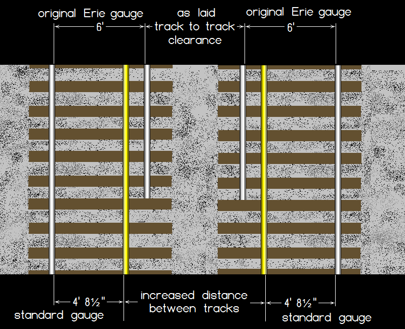 |
Another reason for the decision on moving the center-most rails and not the outer rails, is that already existing station platforms located on the outside (field side) of the rails would have to be extended, which of course would bear the greater expense.
As such; the rights of way, bridges, tunnels and other physical infrastructure of the Erie, were constructed to accommodate the original Erie 6 foot gauge; and were now wider than needed what with the narrower equipment of standard gauge.
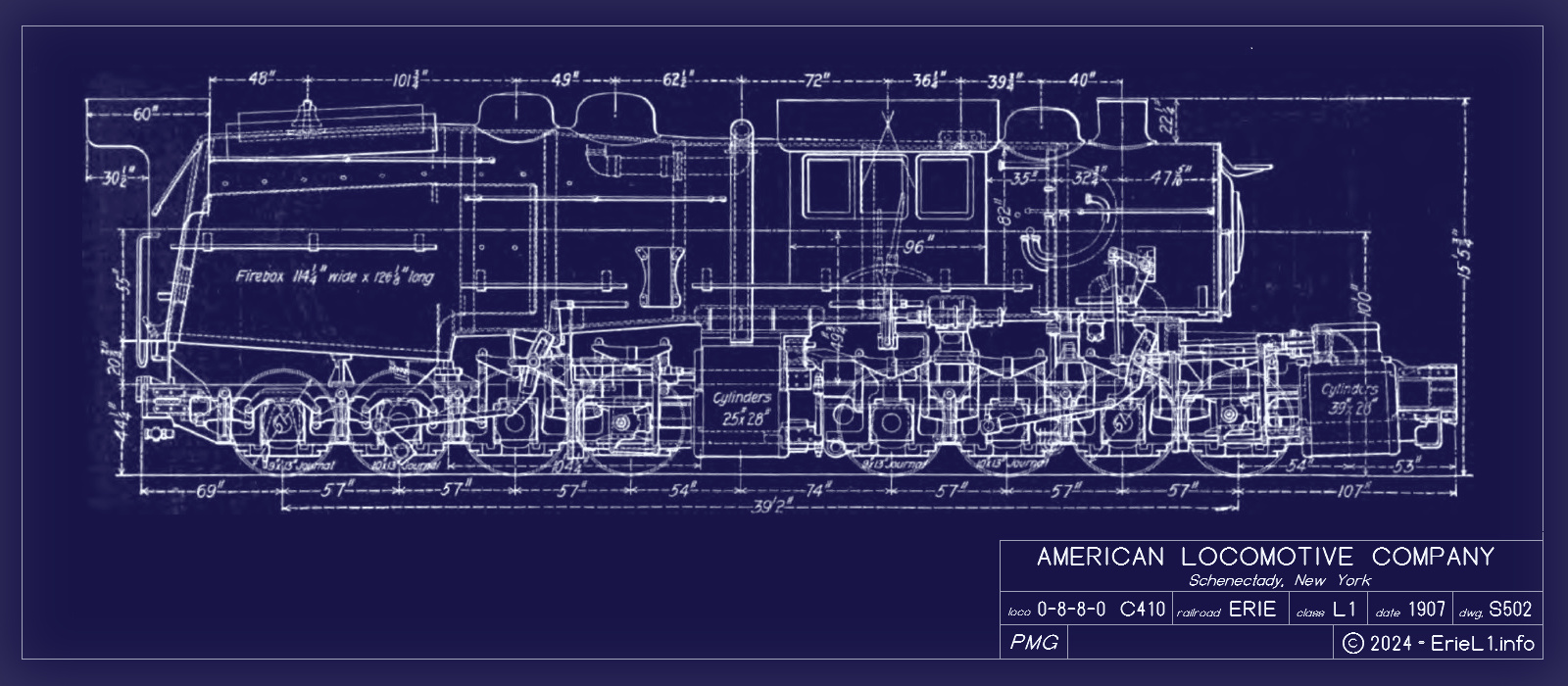
But, as I have stated in Chapter 8.1 above; the L1's would have had to go over the Delaware & Hudson Railroad trackage first, which had NOT been built to wide gauge standards like the Erie Railroad had been.
Therefore, if the L1's did not collide with anything while in transit on the Delaware & Hudson; more likely than not they were not going to collide with anything on the Erie.
But I will admit, this is circumstantial evidence, and that is insufficient to prove my case.
.
8.2
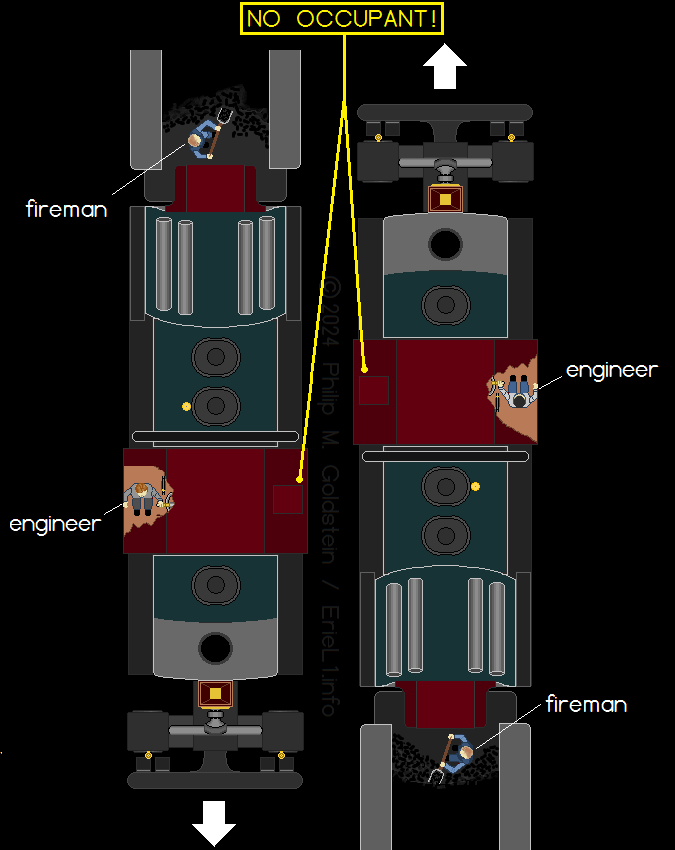
- Exhibit B: Firemen on Camelbacks Were Getting Killed in the Cab
Collisions? Wait. What? Firemen Weren't in the Cab!
Here is yet another point (presented in two parts) to disprove the "defendant's" statement:
|
 |
|
The United States railroad industry (and other railroads
around the world) have
what are referred to as "loading gauges". In the US, Class 1 railroad main line loading gauges began to be standardized in 1886; an were usually published annually; and as seen at right this was the diagram for the year of 1907 - the same year the L1's were constructed. This loading gauge did not apply to narrow or broad gauge operations, streetcar / trolley, or industrial railroads (terminal switching, steel mill, logging, et al.) In 1956, they became better known as clearance plates; but for now we will only concern ourselves with the era in which the Erie L1's operated: 1907-1930. The alleged clearance interference between the cabs of the Erie L1's as allegedly stated by the "defendant"; I refer you to the diagram at right "Railway Line Clearances" as published. Please note, the overall width allowable by a piece of equipment is 15 feet; or 7 feet 6 inches to either side of the centerline of the track. These clearances are for main lines and passing sidings; not secondary lines, industrial or plant sidings, loading platforms at warehouses, coach yards, etc. If one now refers to the diagram below right, which are the dimensions of the Erie L1 as contained within the original American Locomotive Co. plans; we will see that the maximum width, which is the cab of the locomotive; is 151". 151" = 12.58 feet, or slightly over 12½ feet, and is precisely 12 feet 7 inches. Therefore, the maximum width of the Erie L1 is LESS THAN the maximum allowable loading gauge / clearances prescribed for that era of operation. These clearances have existed since 1886 and are the dimensions shown are minimums for standard mainline operation. These dimensions have steadily grown larger over the decades and were contained (in part or in whole) in many public references for new railway construction as well as in standard railroad references (Railway Engineering, Master Car Builders Association, Official Guide of the Railways, et al.) These references were usually published annually and could be found in the offices of railroad physical & mechanical engineers; maintenance of way department heads and track superintendents; among many others. The Official Guide further noted individual size and weight restrictions for each class of freight car for large and small railroad lines and industries. This standard reference could be found in just about every freight depot, yardmasters offices; and on freight traffic directors shelves; Do you think for even one minute, the American Locomotive Company in 1907 constructed a locomotive so incredibly huge, without first checking track clearances, tunnel clearances, and other restrictions on the Erie Railroad where it was going to be used? 8.4: The L1's: Shipping Them Over Two Railroads In addition, the Erie L1's didn't just magically materialize in Susquehanna upon being constructed. They obviously had to be moved from where they were built, to where they were going to operate. The Erie L1's were built by American Locomotive which was located Schenectady, NY. To get to Susquehanna, PA; the most direct route by railroad would have been:
Therefore, the L1's would have had to have their clearances checked for transport over not one, but two railroads: first over the Delaware & Hudson Co. Railroad; and then over the home railroad of Erie; and again, this is before being shipped. Coincidentally, the Delaware & Hudson RR (which was borne out of the Albany & Susquehanna RR in 1870), was also 6 foot gauge when originally laid. As such, the movement of the L1 locomotives over the Delaware & Hudson would have presented any interference of clearances along that route first and before the L1 locomotives even got to the Erie Railroad. (And keep in mind, the D&H operated Camelback locomotives as well.) And in discussion of these clearances, brings us to the next chapter. . 8.5 - Exhibit D: Interstate Commerce Commission Accident Reports Here is another reason how the defendent's alleged "fact" can be determined to be false: By law; the railroads must report all serious injuries and fatalities to the Interstate Commerce Commission: |
|
||||
|
|
"The ICC began collecting accident reports in 1901, but details in those early reports could be sparse.
Starting in 1910, the ICC required that accident reports include the location of the accident and any injuries or deaths that occurred, within 24 hours."
These records have been preserved in the National Transportation Library archives. Furthermore, these records have been digitized and cross referenced by type of various search parameters.
For my research, both here on the Erie L1 locomotives on this website, and in the course of my research on the Rail-Marine Terminals in New York City; I personally have researched these records on numerous occasions.
Unfortunately, there is a small four year gap of records between the start of operations of the Erie L1's (1907) and the earliest date of records scanned to the public domain (1911).
That aside, nowhere is it mentioned in these records; during the operational period of the Angus' between 1911 (when the record compilations begin), through 1921 when they were rebuilt by Baldwin to rear cab (or even to December 1930 when they were ultimately scrapped); that any crewman was injured or killed while operating or in the cab of Erie locomotives 2600, 2601 or 2602; or as the result of a collision with any another locomotive of any type.
The only accidents recorded having taken place with one of the Erie Angus', was a derailment October 10, 1910 (no injuries and reported by the local newspaper); and an injury by a shop employee when a broken stay-bolt blew out of the firebox under pressure, and injured the worker.
Both of these incidents are mentioned in further detail in the chapter: L1 Mishaps
Before defense has an opportunity to cite incomplete accounting, I submit the following additional exhibit.
.
8.6 - Exhibit E: Sponholtz Compilation
Apparently, I am not the only one to have researched these ICC records, because in my searching the web for injury / fatality reports for the Erie prior to 1911, I encountered the following webpage:
ICC Reportable Accidents and Other Events - Erie Railroad; by James Sponholz
Mr. Sponholz's research went one step further over and above the ICC records, by referencing newspaper article archives on the Erie Railroad in searching for those accidents.
His compilation is tabulated by date, division, nearest town, the injured party's position of employment, as well as locomotive numbers and type of train; when applicable. His compilation goes back farther in time, to 1869; using these newspaper accounts; and of which further helps fill in the gap of 1907-1911 as mentioned above; and when the Erie L1's first entered service.
Once again, I searched through all the entries; and once again, nothing was found regarding any accident involving Erie #2600, 2601 or #2602; where they operated. I even expanded the geographical areas to include Port Jervis and Binghamton. Nothing.
.
8.7 - Exhibit F: Erie Railroad Rule Books
To further drive home the fact that the defendent's statement is blatantly false, if a said conflict of clearances were to exist between any locomotive to any other locomotive or fixed object, it would be so stated in the Rule Books issued to employees for that time period.
Since I own the very Rule Books and Special Instructions from 1908 through 1930's (for when the Erie 0-8-8-0 Mallets operated); these Rule Books are scanned and presented in Chapter 23: Erie RR Rule Books & Special Instructions. The jury and the court are of course invited to look through them for yourselves.
Not a single Rule Book or Special Instructions Book issued by the Erie Railroad defines or specifies a clearance restriction for the Erie L1's operating on opposing tracks, other than those regarding weights on certain bridges when in operation with similar class or other heavy locomotives.
These Rule Books and Special Instructions are the very last word in regards to these operational conditions. If it is not listed or prohibited, there was not a rule for or against to the point. It should also be mentioned that the engineers had to carry these rule books on duty.
Perhaps what is most astounding about the defendant's statement, is how anyone can believe for even a single minute that even after the first such (alleged) incident of the cabs colliding between two Erie 0-8-8-0's operating side by side; that the Erie would have not remedied the issue immediately; and would allow it to continue repetitively. And by allowing the situation to continue, thereby killing "multiple" numbers of engineers and fireman?
Furthermore (and removing the human element out of this equation); is it the assumption that the Erie Railroad would allow these locomotives, read: expensive pieces of equipment; to be damaged once and again, to the great expense of time out of service, labor to repair and monetary expense of both.
Quite obviously this is not the case, because the Erie was not running a demolition derby.
Any railroad as a whole: whether corporate mechanical engineers down to the divisional superintendent, down to individual shop superintendents at the local level; would never intentionally allow any defect that would routinely damage extremely expensive equipment, not to mention remain a danger to the crews.
The locomotive builders and the railroads were incapable of that level of incompetence, to say the least.
But apparently the defendant believes they did.
The prosecution hereby
rests your honor.
Your honor, the defendant would like to change his
plea of not guilty to guilty by reason of insanity.
So accepted. The court hereby imposes
sentence upon the defendant of:
a) being confined to mommy and daddy's basement to play with his model
trains,
b) not to impersonate someone who thinks they know
what they are talking about;
Sentencing for a period not less than old age, and
not greater than eternity. So ordered.
.
31,763 miles divided by the three locomotives = 10,587.6 miles per locomotive, for that 6 month period.
10,587.6 ÷ 6 (months) = 1,764.6 miles per locomotive per month.
1,764.6 miles per locomotive per month ÷ 30 days = 58.82 miles per day
58.82 ÷ 17 miles (1 round trip Susquehanna to Gulf Summit & return; or Deposit to Gulf Summit and return) = 3.46 trips per day
(Obviously, you can't have 3.46 trips, so let's just round this down to 3 trips.)
31,763 miles divided by two on duty locomotives = 15,881.5 mile per locomotive, for that 6 month periodThis number is lot more conducive with the amount of trips the locomotives are known to have taken on an average work day.
15,881.5 ÷ 6 (months) = 2,646.9 miles per locomotive per month.
2,646.9 miles per locomotive per month ÷ 30 days = 88.23 miles per day.
88.23 miles ÷ 17 mile round trips = 5.19 trips per day; (or 5 trips).
| Run | Time | Elapsed Time (Minutes) |
Notes |
| 1 | 09:25 - 10:25 | 60 | |
| 53 | coast downhill & wait | ||
| 2 | 11:18 - 13:11 | 113 | This
run is actually marked as Run 3 in the Thesis, but the clock times as
noted are then out of sequence for those of Run 1 and Run 2 Also, this was the run as listed as having an inexperienced fireman who let the steam fall below usable pressures. |
| 156 | coast downhill, possibly took on coal | ||
| 3 | 15:47 - 16:50 | 63 | |
| 10 | coast downhill | ||
| 4 | 17:00 - 18:08 | 68 |
| railroad | locomotive type | # built | usage dates | service life | notes |
| Union Pacific | 4-8-8-4 "Big Boy" | 25 | 1941 - 1962 | 21 years | And the Big Boy's are undoubtedly considered successful. |
| Union Pacific | 4-6-6-4 "Challenger" | 105 | 1936 - 1958 | 24 years | Some were rebuilt to fuel oil and other modifications at midpoint through their lives. All successful. |
| Norfolk & Western | 2-8-8-2 "Y Class" | 16 | 1942 - 1959 | 17 years | Successful. |
| Chesapeake & Ohio | 2-6-6-6 "Allegheny" | 60 | 1941 - 1956 | 15 years | Successful. |
| Norfolk & Western | 4-8-4 "J Class" | 14 | 1941 - 1959 | 18 years | Successful. |
| Reading T-1 | 4-8-4 "Northern" | 30 | 1945 - 1959 | 14 years | (originally built as 2-8-0's in 1923); heavily reconstructed in 1945 to 4-8-4. |
11.1: One Fireman Returning to the subject at hand (pun intended), the three Erie 0-8-8-0 locomotives as built, were originally hand fired (meaning a fireman had to hand shovel coal into the firebox). It should be noted these locomotives has 100 square feet of grate area and the locomotives were equipped with two doors on the backhead. Due to these two doors, it is quite frustratingly stated repetitively in internet groups, that these Erie locomotives utilized two fireman, one for each firebox door. . And it is this, without any room for doubt; which is the most prolific case of misinformation regarding the Erie L1's. Recently added to my collection is the June 1970 issue of Railroad Magazine. This issue contains a five page article on "Erie's Monster Mallets", pages 30-34 as authored by Robert A. Le Massena. While most of the article is concerned with the Triplexes, there is a brief mention of the L1's; and sure enough it is stated the locomotives "gulped steam in such vast quantities that two fireman were needed to spread coal over the 100 square-foot grate." ► By
all historical accounts and documents, this is not the case. ◄
Official railroad recordations and documents to date, indicate they were fired by a single fireman. This is confirmed through official documentation, namely the The Erie Dynamometer Test - 1907; as well as the Cullen / Gridley - Cornell U Thesis - 1908. I think it is safe to conclude the railroad and University engineers of that era were a little better informed to the staffing requirements than some railfan's assumptions half a century later. I know what you are thinking, aren't I (mean the author) a railfan? Yes, however I am drawing my conclusions from official documents from the era, not erroneous information being repeated a century after. If one actually takes the time to read the historical accounting of the design of these locomotives as written in Erie Power (as seen above); references are made, several times in fact, to a singular fireman: . . "... Hand fired loco had two fire doors to facilitate spreading coal over that huge grate area. Also handy if you wanted you use two fireman." Not: Locomotive had two fire doors for two fireman, nor anywhere in the chapter does it specify two fireman were needed to fire this locomotive. "... if you wanted to use two firemen" not "when you used two fireman" or "for two firemen". The use of the second fireman was an option secondary to the need of covering the grate area with even coals. One fireman was the norm, and nothing about this locomotive required noting or needing a second fireman in normal operation. . . "... On the other hand it had the effect of speedily draining the boiler of steam which on a hand fired L1, did much to prevent a fireman from viewing the majestic panorama from Starrucca Viaduct." Reference to a singular person "a fireman", not the firemen. Also this reference to "speedily draining the boiler" was in reference to the simple / compound intercepting valve being set for simple instead of compound. According to multiple documents; the majority of the time and in normal operation, the intercepting valve was set for compound; with the simple position being reserved for emergency situations of having to start the locomotive from a dead standstill on the grade with a load. . . "... several runs showed one good fireman could get plenty of power from an L1 Mallet without being taxed to the point of collapse." Again, reference to a fireman in the singular: "one good fireman", not firemen in plural. . . On page 18, in the Cullen / Gridley - Cornell U Thesis - 1908 upon their observing the The Erie Dynamometer Test - 1907 it is stated: "The Coal... it was weighed and dumped out for the use of the fireman." Once again; for the use of "the fireman", in the singular. . . In the photo of #2602 that appeared in the Alexander book, again, one man by the air compressor (the fireman), one on the walkway in front of the cab (the engineer) and one on the pilot (the brakeman). Three men: One fireman. One engineer, one brakeman / switchman. . Some of you may wish to point out in some of the photos, there are more than three crewmen. I refer you to the Erie Rulebook which stipulates: "Pusher locomotives between Susquehanna and Gulf Summit will be provided with flagman." Normally, there was no conductor for pushing locomotives; as conductors were assigned to the through train the pusher locomotive was assisting. Some of the photos show men in suits. Obviously they are not part of the crew. It is also understood the Port Jervis taken in 1911 image was an Erie publicity photo (hence the suit clad men) and other employees were included in the image. And, saving the best proof for last; in the dynamometer car tests conducted in 1907 by the Erie Railroad; the written context of The Erie Dynamometer Test - 1907 makes reference to several times to "the fireman', (in the singular) and not "firemen" (in the plural) and this official document holds additional and necessary confirmation of the assignment of a SINGLE fireman to fire the locomotive: . .
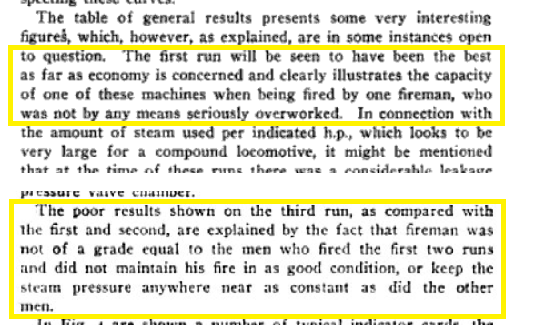 I submit verbatim: "... clearly illustrates the
capacity of one of these machines when being fired by one
fireman, who was not by any means seriously overworked."
"The poor results of the third run,
as compared with the first and second, are explained by the fact that fireman was
not of a grade equal to the men who fired the first two tests."
"fired by one fireman", "That fireman". In the SINGULAR. <Mic
drop>
It is indeed unfortunate some railfans cannot fathom such a large locomotive being singularly fired. Yet, according to all archival sources, it was. Part of the reason for the construction of the L1's was to reduce the need for multiple smaller locomotives required for pushing, and this was to include saving on manpower by eliminating an engineer and fireman on each of the pusher locomotives, which were used in multiples. When referencing the misconception of the second firedoor equaling a second fireman; the placing of that second fireman on the L1 (as it is wrongly assumed) would have partially negated that savings in manpower and defeated the purpose of the design of the L1 in the first place. Perhaps some of you may have visons of that scene in "Emperor of the North" where 'Shack' and 'Coaly' are shoveling in coal as fast as they can to get out of the way of fast mail they are about to meet head on; or in the movie "The Train" with 'Pesquet' and 'Didont' are frantically shoveling coal to outrun the RAF fighter. But that is not the case here. The L1 was a locomotive designed for slow speed pushing over a short limited distance; not main line, requiring fast speed over a long distance. Also, it is pertinent to read the operations manuals and trade literature of that era and pertaining to the locomotives and railroads of that day. Fortunately, these publications are readily available for free on Google Books, and I have included them below. And now, I shall explain the actual reason for two firebox doors. . 11.2: Dual Firebox Doors: It Doesn't Mean There Were Two Firemen! It should be noted it is now understood that the Erie L1's used both anthracite culm OR bituminous coal. The Cullen / Gridley - Cornell U Thesis - 1908 clearly lists the coal used during the The Erie Dynamometer Test - 1907 as bituminous, from Erie Railroads' own Dagus Mine located in Kersey, Pennsylvania. Oddly enough, in my research about this mine; this supply could not have lasted much longer after the test; as the Dagus Mine closed in 1907; when production and supply commenced at the Brockway Mine. Both were part of the Shawmut Coalfield located in Elk & Jefferson Counties of Pennsylvania. As the 1907 test incurred no special preparations; it can be concluded that the coal used during the test was used as well in regular service, and of which was dispensed at the Susquehanna Coaling Tower near the shops for all locomotives.
Mention of these dual firebox doors are noted in the Wide Firebox chapter as contained in The Railway Engineer, February 1907 There was more involved to maintaining a fire in a locomotive then just shoveling a load of coal in and slamming the firebox door shut. Several different tools were necessary to even out and maintain that fire; which are illustrated below and being able to access the entire firebox with those tools, was quite important.
.
So, to make a short story long; two firebox
doors did NOT mean two firemen.
It meant easier accessibility for ONE fireman to tend the coals on either side of the grate to efficiently fire the locomotive, especially so on those locomotives equipped with a wide Wootten firebox for burning anthracite culm! Think of this analogy: you can fit four people in a two door coupe, but a four door sedan made it easier for all four to get in and out. And having a two door coupe didn't mean there were two drivers, likewise a four door sedan didn't equate to four drivers. And, a two door coupe with really big doors also made it easier for people in the back seat to enter and exit. I wonder if I have gotten the point across yet? . . . . . . It was more than sufficient, because
it only had to go so far...
It is often noticed and commented on, that the tenders of
the L1's were small in
comparison to the size of the locomotive. The tenders used by
the L1's had capacities of 16 tons of coal and 8,500 gallons of water. . And, unfortunately once again it is often assumed by the unknowledgable that this "must have limited the L1's usefulness or success". Yet once again, this is a false assumption. Due to the L1's limited area of operations, the L1 locomotives did not venture far from coal or water facilities. Its primary assignment was pushing the train up to and over Gulf Summit, with the L1 being uncoupled at the summit and coasted back downhill to its originating point, whether that be Susquehanna or Deposit. This method of operation is described in detail in the trade journals below. So, its normal service distance during regular operations; an L1 locomotive only had to pushing a heavy loaded train 8½ miles upgrade from Susquehanna to Gulf Summit, or from Deposit to Gulf Summit. If; for whatever the reason, the locomotive was in Susquehanna, PA and was needed in Deposit, NY; that still equated to only 17 miles one way or 34 miles round trip. And at 15 miles an hour, this was just over an hours service time between pushing a train over the Gulf Summit to Deposit and returning, including the time required in getting their telegraph orders, uncoupling from a train, and throwing the switches and switching to the appropriate eastbound or westbound track for the return trip and returning the switches to normal position. This would be like expecting a small yard switching locomotive to have a long haul tender. Those locomotives did not venture far from their fuel and watering facilities either, so a large tender was totally unnecessary for the assignment. The Erie Railroad facilities at Susquehanna were quite extensive: there was a large machine shop and roundhouse: 774' by 138' with room for up to 40 locomotives; a boiler shop, a blacksmith's shop, a pattern shop, a paint shop, a foundry and engine rooms for the equipment in the various shops. It also was the location for both the coaling tower and water tank of 55,000 gallon capacity (pump fed); where as the Deposit, NY location offered only a water tank of 33,000 gallon capacity (gravity & pump fed). Should an occasion so arise where an L1 would have to make a longer journey, say for example, to Port Jervis the next largest terminal east of Susquehanna; this was just under 100 miles from Susquehanna; and equated to 3½ hours running time. 12.1 - Coal Consumed
According to the Cullen / Gridley - Cornell U Thesis - 1908; the L1 used the following pounds of coal during its four trips tested:
Thereby, dividing 19,980 lbs. by 4 trips give us an average of 4,995 lbs. or roughly 2½ tons per trip. Further dividing 4,995 lbs. by 17 miles round trip equals 293.8 pounds of coal per mile. That may sound like a lot, until you consider the standard railroad coal scoop (shovel) handled and average of 20-30 pounds of coal per shovelful. This equates to "only" ten to twelve shovels per mile. And most of that shoveling was only needed going uphill, when the locomotive was working hard; not as the locomotive idled while waiting for the train to be pushed to arrive and to pass and to couple onto the rear of; or waiting to be uncoupled from; waiting for switches to be thrown, and certainly not as the locomotive coasted back downgrade to its starting point or simply waited for a heavy freight train to arrive, that would needed assistance. So from these figures, we can extrapolate that the tender and its 16 ton coal capacity was quite sufficient for about 6 round trips. At an average of 78 minutes per trip, equals 468 minutes or 7.8 hours; or more than half of a 12 hour shift. 12.2 - Water Consumed
According to the Cullen / Gridley - Cornell U Thesis - 1908; the L1 used the following pounds of water during its four trips tested: 43,410, 20,540, 40,270 and 48,920. First, we have to convert those pounds of water to gallons. Water weighs approximately 8.3 pounds per gallon, therefore: 43,410 ÷ 8.3 = 5,230 gallons 20,540 ÷ 8.3 = 2,474 gallons 40,270 ÷ 8.3 = 4,851 gallons 48,920 ÷ 8.3 = 5,893 gallons The sum of 5,230, 2,474, 4,851, 5,893 equals 18,448 gallons. 18,448 gallons ÷ 4 trips = 4,612 gallons per round trip. 4,612 gallons ÷ 18 mile round trip = 271 gallons of water per mile. 8500 gallons capacity tender ÷ 271 gallons per mile = 31 miles per tender of water. This may not seem like much, and here I will agree, it isn't. But it is a generally accepted rule, that a working locomotive uses a 10:1 ratio of water to fuel. Hence why almost every town along a rail route had a water tower or standpipe; not just for this locomotive model, but for most others. As listed in the Erie Official List #7, issued January 1, 1909, here are the following locations with water facilities on the Delaware Division. Notice they are not more than ten to twenty miles apart from each other:
Again, this was under hard working conditions pushing 3000-3500 tons up a 1.36% incline for 8.5 miles, then coasting down in the other direction. Normal, more moderate working conditions would of course use the water more sparingly and increase the operating distance. 12.3 - Operations over Longer Distances
Naturally, the amount of coal and water consumed would be less if the locomotive was working moderately easy, on mostly level ground along the banks of the Susquehanna River; or as the railroaders call it "river grade" Say a trip from Susquehanna, up and over Gulf Summit (hard working), down to Deposit (coasting); and then all the way to Port Jervis (easy working); a distance of 104 miles. Only the first 9 miles would be hard work, then the locomotive would coast down, then resume easy to moderate pushing work in Deposit, albeit not working nearly as hard as shoving up Gulf Summit. But the numbers above are for "hard work" for 8.5 miles, with "coasting" or "idling" the next 8.5 miles, then "regular work" for 88 miles, which would use significantly less coal and water than "hard work". For the sake of this calculation however, we will use a worst case scenario of "hard work" for the full 104 miles: Coal: 104 miles x 277.5 pounds of coal per mile = 28,860 pounds of coal or 14½ tons; (rounding up - call it 15 tons) Water: 104 miles ÷ 31 miles per tender of water meant an L1 would have to fill up about 3.3 times; (again rounding up - call it 4 times) So Port Jervis was easily with the capability of an L1 with a full tender of coal, but the locomotive would have had to stop 4 times to fill up the tender with water. This is not an unusual amount for the type of tender over that distance. Additionally, it should be understood most towns along that segment of the Erie Railroads' Delaware Division had either a standpipe or water tower, so a trip with "only" a 8,500 gallon water capacity and 16 tons of coal, was not detrimental to the locomotive operation or a significantly delaying factor; if it was even required. The distance to the next terminal west, would be Binghamton, which was 22 miles, short enough without having to stop for water or coal. Therefore as you can now understand, a large capacity tender (such as those employeed for long hauls) was not necessary to the daily operation of the L1. As the L1's (and Triplexes) never ventured far from either of its home terminal of Susquehanna, it therefore could be fueled twice and watered several times a shift if necessary. For comparison, the Matt H. Shay "Triplexes" (Erie Class P-1) - for all their size - also only carried 16,000 pounds of coal (same as the Erie L1's), and only 1,500 gallons more water (10,000 gallons vs. 8,500). Again, it needs to be reiterated: the Erie L1's were not cross country / long distance locomotives; like Challengers, Big Boys, Alleghenys, Chesapeakes, Yellowstones or any other large articulated locomotives with a long haul tender. Those carried a lot of fuel and water to cover large distances without stopping frequently. That was not the case for the L1, which was almost never more than 17 miles from its "home". Hauling a locomotive tender that was larger than needed and further than it needed to go, was inefficient to say the least. . . . . 13.1 - Why Erie Ordered the L1's
The main purpose for the design and construction of the L1 Mallets was to reduce the need for multiple pusher locomotives per train and with that, a reduction of locomotives; and commensurate, a reduction in manpower; as each pusher locomotive required an engineer and a fireman. Three pushers equaled six men, not including the men on the head end locomotive(s) which could be two or even four men if the train was double headed. In short, a single train could have ten crewman not including the conductor, brakemen or flagmen (of which were assigned to pusher operations). Thirteen men to move one train. That is quite the crowd. The average freight train climbing Gulf Summit and of that era could be comprised of 50 to 70 cars, and ranged between 3,000 to 3,500 tons. Prior to the arrival of the L1's in 1907; the locomotives primarily assigned to pusher service over Gulf Service were the S1 class 2-10-0 "Decapods" in 1891 and the H10 Class 2-8-0 "Consolidations" in 1900. 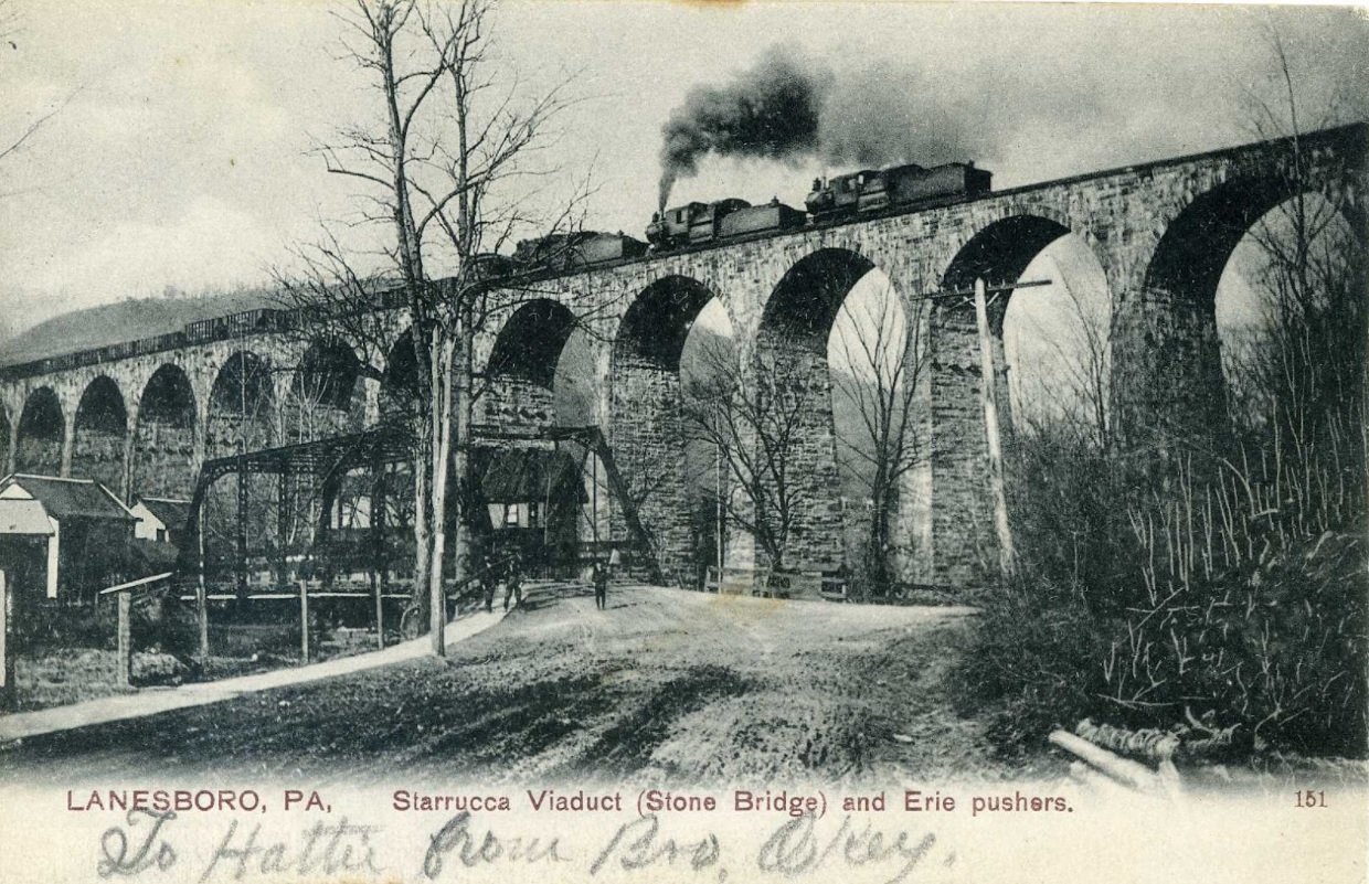 Here we see three locomotives (which appear to be H10 class 2-8-0 Consolidations), pushing a loaded hopper train eastbound; Each H10 weighed 313,400 lbs. total loaded and developed 37,500 lbs of tractive effort each so three H10's would total 940,200 lbs in weight and 122,500 lbs in tractive effort. So, depending on the tonnage of each train and the tractive effort of the lead locomotive(s), as well as the tractive effort of the pusher locomotives available; each train would require at least one, and up to three pushers. Engineer and fireman times three locomotives equals six men. The reason so many locomotives were needed, was to develop the necessary tractive effort required to start and maintain movement of a train. The tractive effort required consists of the consideration of numerous factors, but for most applications only four factors need to be considered.
So, in having to push trains over Gulf Summit, multiple locomotives were required. In some cases two locomotives were double headed on the lead end, and two pushers placed on the rear of the train. This equalized the forces between pushing and pulling. Too much force on the pulling end would break coupler knuckles or drawbars; and too much force on the pushing end could twist a car, break a frame or just simply buckle the train into a derailment. While it is thought that any heavy freight service locomotive would have been suitable for assisting trains up Gulf Summit, only a few such classes were actually suitable and therefore actually designated and assigned in Susquehanna for regular pusher service. These were: ."H class Consolidations (2-8-0), . 13.2 - Comparison of Erie Freight Locomotive
Classes
A comparison of freight locomotive classes that operated during the life span of the L1 are listed below. Light duty locomotive classes are omitted. The experimental M Class (even though short lived) and P Class Triplexes are included as both were intended for the same service duty as the L1. Also included is the K1 class passenger locomotive as due to its weight, was prohibited from operating in conjunction with a Mallet over Lanesboro and Starrucca Viaducts as proscribed in the rule books.
The main issue that was encountered using 2-10-0 or 2-10-2 wheel arrangement locomotives on the Erie's Gulf Summit, was their long driver wheelbase: up to 22 feet 6 inches on the 2-10-2's. When taking into consideration the plethora of curves on the Gulf Summit run between Susquehanna and Deposit, these rigid wheelbases were the upper limits of suitability for the trackage curvatures. These locomotives had the tractive effort, but not so much the agility or flexibility to negotiate the curves with minimal resistance. Their rigid wheelbase would also cause wear on the inside face of the rail head quicker than those of shorter wheelbase. In short, a minimum of eight men for one train, and this does not yet include the conductor of the train, brakemen which were also assigned to the trains or the switchmen to operated the switches at Susquehanna and Gulf Summit. When freight traffic was heavy with several trains present and waiting for "a push over the hill", the pool of locomotives could be depleted rather quickly. Reducing the amount of locomotives needed to push a train, also reduced the time involved in servicing and maintenance of each of those locomotives both daily as well as the monthly shop servicing as required. 13.3 - Potential
Drawbacks
However, this replacing of three locomotives with a single locomotive was not without issue either. With reduced numbers of locomotives assigned, when one out of the two locomotives suffered a mechanical failure, the train tonnage could not be averaged out among the three (or more) remaining locomotives as it used to be. This is why Erie ordered three L1's: two for service, one as standby. This is a similar dilemma in regards to modern day freight railroad operations and a result of the horsepower race of diesel locomotives; the higher the horsepower of the single locomotive, reduced the need for multiple locomotives of lower horsepower. In other words: four locomotives of 2500 horsepower equals 10,000 horsepower. If one locomotive failed, you were reduced to 7,500 horsepower. But chances are the locomotives were not being operated at their maximum ratings, so there was even a little leeway in asking them to do a little more. But as 4000, 4400 and 6000 horsepower locomotives were developed, less locomotives were assigned to the train, with most of the time only two locomotives totaling 8000, 8800 to 12,000 horsepower were needed to be assigned. But, when one of those two units failed, the train lost half instead of a quarter of its horsepower. This is where locomotive reliability factors into the equation. And this applied to steam locomotives as well. Enter the L1 Articulated Mallet. Each L1 replaced three H10 Consolidations (six crewmen) or two S1 Decapods (four crewman). It was easy on the curves - and easy on the eyes ;) 13.4 - The L1 versus the P1 Triplex
For comparison, the L1's were built in 1907 and had been operating reliably as built for seven years, when the first P1 Triplex; #2603 (quickly renumbered to 5014), and better known as the "Matt H. Shay" arrived on scene in 1914. The initial P1 Triplex was designed by George R. Henderson, consulting engineer at Baldwin Locomotive Works. Built with Schmidt firetube superheaters, with 53 elements and 1,584 square feet of heating surface; of which this was the largest superheater incorporated into any locomotive at that time. A Street mechanical stoker eliminated hand shoveling. The feedwater pumps as first installed, were powered off the crossheads behind the cylinders, but these turned out to be woefully insufficient. They were subsequently replaced with steam powered reciprocating feedwater pumps those of larger volume and on the boilers right side. Also, there was to be no intercepting valve like on the L1's; so the Triplex was "compound only." Also, it was not built with a Wootten firebox, but a Gaines firebox with combustion chamber and were fired with bituminous coal. The Triplex as designed by Henderson was to be dual service: that is, it could be assigned to either as a leading locomotive (pulling) or as a pusher. As lead locomotive, it was so intended to singularly haul a freight train consisting of 640 fifty ton freight cars, equaling a train 5 miles long. Before being released from Baldwin Locomotive Works, the Matt H. Shay was taken on a trial run as a lead locomotive on the Philadelphia & Reading Chester Branch. It was then demonstrated on the Baltimore & Ohio, and again the locomotive by itself; hauled a loaded coal train of 55 cars equaling 4,012 tons; departed from Baltimore, Maryland at 6:10 am and arriving at Philadelphia, Pennsylvania at 4:30 pm. This equates to 10 hours and 20 minutes to travel 90 miles, or an average of 8.5 miles per hour. Allegedly; it is on this run that a low bridge ripped off the steam dome off the locomotive. I can find no reference to this incident, but this might account for the trip taking 10 hours; however this is not confirmed. It was finally delivered to the Erie RR at Susquehanna, PA and entered into revenue service as intended as a pusher on Erie's Gulf Summit between Susquehanna and Deposit. Here it was determined the 90 square foot grate area of the firebox was insufficient, the locomotive sent back to Baldwin for modifications and the grate area enlarged to 121.5 square feet by removing a portion of the brick arch and shortening the combustion chamber. This enlarged grate area would be built from the start for the two subsequent Triplexes (5015 & 5016). A tonnage test was performed by the Erie with a 130,000 pound capacity dynamometer car between Binghamton and Susquehanna. The train consisted of 250 loaded cars; was 1.6 miles in length and 17,912 tons. The test used pushing engines (unspecified which) which were used for starting to avoid pulled draft gear / broken couplers. The Triplex achieved a top speed of 14 miles per hour and "maxed out" the dynamometer car recording device; but as feared, the train parted at a weak spot. Despite this; the Erie was satisfied with the pushing performance of the Triplex, and ordered two more (#5015 and #5016) which were delivered in 1916. Upon delivery of the second and third locomotives, Erie even tried using them as a mid-train helper, but this was time consuming process. It is recorded, that all too often; that only one P1 was in working order most of the time; and due to their size, Erie's Susquehanna Shop could not service or repair them. The Triplexes were required to be sent to either the Lehigh Valley Railroad's Sayre Shops (65 miles away) or Erie's Dunmore Shop (50 miles away) for major repairs. While these are relatively close, this was still farther away than its home shop of Susquehanna. It is stated in Erie Power, that the summation of the P1 amongst those men that operated them was thus: "too many legs, not enough boiler". Furthermore, some men believed if the feedwater heaters worked as intended, the outcome would have been a better steaming locomotive. Despite being built later than the L1's, and with all the appliances modern to that period, it is documented that all three P1 class were out of service by 1927, and were scrapped on the following dates: 5014 in October 1929; 5016 in March 1930, and 5015 in February 1933. The P1 Triplexes for all their ballyhoo; only operated thirteen and eleven years respectively. And this was only after the prototype returned to Baldwin for modifications and the subsequent two incorporated the changed specifications. Yes, the Triplexes were more powerful in regards to tractive effort to the L1: 94,070 vs. 160,000 ft lbs. for the P1; but their design flaws and feedwater issues ultimately hindered their performance as designed. Something else I can't help but wonder that might not have helped the P1's: we know from history they were originally planned to be used as pulling engines; and they were equipped with 63" drivers. Larger driver diameters almost always equates to higher speed operation. The L1's were equipped with 51" drivers - a foot shorter. We know the L1's did not move fast, and they weren't designed to. But it begs the question, had the P1's incorporated a slightly smaller diameter driver, would they have performed any better? Nevertheless, the L1's were satisfactory from the start, and according to all documentation they served without any modifications to their original design. Even after rebuilt with "modern" appliances in 1921, to which they served another 9 years; for a total life span of twenty-three years. Again, all documentation to this day reflects reliable operation of the L1's over their lifespan. Thus, the L1's actually outlived the more powerful and more "advanced" P1 Triplexes by three years. And, I can't help but wonder if perhaps some railfans might be confusing the issues of the P1 Triplexes for the L1's? .. . . . This one again? They were not unsuccessful. Not in the least. Let us add up the numbers. 14.1 - Starting from the first Compound
Mallets Built
Baltimore & Ohio RR #2400 "Old Maud", an 0-6-6-0; was the first compound Mallet to be built in the United States, and proved to be successful. Built in May 1904 (ALCo c/n 27478), 20" x 32" rear and 32" x 32" front cylinders, with 56" drivers; she operated as built until 1926, at which time she was rebuilt to simple expansion (20" x 32" cylinders all around). This earned her 12 more years of service, before she was scrapped January 1938. One locomotive built; 22 years until rebuilding, 12 years more service after rebuilding, total: 33.5 years of service. She proved that the concept of Articulated Compound Mallets had a place in American railroading.
The following five compound
Mallets that were built, were in 2-6-6-2 wheel arrangement built by
Baldwin Locomotive Works for the Great Northern
Railway, #1800 #1801, #1802, #1803, #1804. Baldwin
construction
numbers 28601 (#1800), 28641 (#1801) built in July 1906; 28739 (#1802),
28854 (#1803) in August 1906; and 28933 (#1804) in September 1906.
These were built with 33 x 32" front cylinders and 21½" x 33 rear
cylinders and 55" drivers. They would all be rebuilt after 19 years to
2-8-2
wheel arrangement 11/1925 - 6/1926. These broke the ice, as the Erie L1's were the next three Compound Mallets to be constructed. But we still have not come to any reasonable conclusion why the Erie L1 Mallets were considered "unsuccessful". . . 14.2 - Subsequent Compound Mallet orders
Furthermore, if the Erie L1 design was "not successful" (and no one has quite yet said specifically or conclusively stated what was wrong with the L1 design...), then why did American Locomotive see an ever increasing amount of orders for articulated Compound Mallets, built on the same principal design, beginning a year after the three L1's were built in July 1907?
This "short list" above excludes those Mallets built for both export, and domestic narrow gauge operations - I restricted the list to standard gauge domestic operations. Furthermore, this list only pertains to what American Locomotive Company built in the 2-3 years after the L1's were built. I have not even begun to list what Baldwin or Lima built; and I have excluded simple expansion articulated locomotives (not that many were constructed that early). So, if the design of the Compound Mallet was "unsuccessful"; then why did so many railroads order this type of locomotive, and why did these locomotives live to see the 1930's, 1940's and 1950's? Because they were successful. Notice some railroads only ordered one or two Compound Mallets. Some ordered five or six. Did these limited order quantities constitute an unsuccessful design? No.
A successful design is not proportionate to the quantity of locomotives ordered. If a railroad orders one, it *might* be to see if that design is suitable for their needs. When that railroad orders more of the same type with no modifications, the first was apparently suitable. When a railroad orders three or five or twenty-four, that is because they have passed the testing stage and they order what they need. But an order of only one locomotive or two or three does not equate to an unsuccessful design. . The supposedly "small" tenders carried the accepted amount of coal and water, and used them in 10:1 proportion to other locomotives of those type and service assignment. So the tenders weren't "too small to be useful". . And we can see some were scrapped in 1929 (at 19 years old), and others made it to the 1950's. So longevity / reliability of the L1's at 14 years of service before rebuild, and then 9 additional years after rebuild to retirement is not the reason either. . Erie opted instead for a dedicated locomotive design for helper / pushing service, for the dedicated area of Gulf Summit. I can keep on going if you need me to, but I think I have made my point: that the Erie L1's were in fact successful, reliable, had just the right size of tender, and did what they designed to do, over the course of the normal average lifetime of a locomotive assigned to severe duty service. So, if after reading any one or all of the preceding chapters; and the light bulb goes on over your head and you say, "Now I understand!"; you have earned my respect and a warm hearty welcome to the club of informed knowledge.And, now there is one less mis-informed person out there thinking the Erie L1 0-8-8-0's used two fireman or the locomotive were unsuccessful. That wasn't such a long walk, was it? . . . Despite the revelations and the vast amount of information that these rule books contain, I can find nothing in either about restrictions regarding the placement of a caboose between the pusher locomotives and the train. This is a pertinent question, and it is often debated in railfan groups. It is stated by Westing in Staufer's "Erie Power" on page 180: "The
helpers are NOT PUSHING ON THE CABOOSE - and reasons are obvious. Not
all cabin cars (Pennsy term) are build to withstand the unbelievable
thrusts with the push-pull effect of engine on each end of the train.
the two gargantuan Berks are leaning into the train to the
tune of
150,000 lbs. - tractive force delivered by over 7000 cylinder
horsepower.
The following is the accompanying image to that caption, with what appears to be a steel caboose behind the two locomotives: 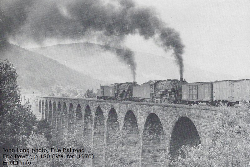
Yet in direct contradiction, we see in the very same book as well as postcards of the era; many images of a caboose (whether they be wood or steel construction) between the pusher locomotive and train, or a caboose between the two pushers on the end of the train, sometimes with a second caboose behind the second pusher: p. 147, 159, 160; and 180. Furthermore, a caboose (regardless of construction) in front of the pusher may be unoccupied, but that caboose could just as easily be crushed or derailed with the forces of a pusher engine behind it, as an occupied caboose can be. Aside of the human safety factor which I completely understand and accept; I have difficulty believing that would be the railroad's sole concern. A caboose may not have been the most technologically advanced or expensive piece of equipment found on a railroad, and it still has a financial value in case of damage or loss. Not to mention the delays to that and subsequent train movements and the labor in having to remove the wreckage. Especially so if such an occurrence was to take place while traversing over Starrucca Viaduct? It is 110 feet to he bottom and would make for a mess! So why leave the caboose in front of the pusher engine, irregardless? Without knowing the construction of the particular models of caboose in the images or locating the legislation in black and white; I regret to say; I just do not know at this time. If you do, please feel free to contribute at bedt14@aol.com
So for the time being, I have nothing concrete in the way of Erie Railroad rules pertaining to placement or position of a caboose, whether it be wood or steel; and whether between a pusher and its train or behind the pusher. 15.2 - A
State Regulation?
On the state level, I did locate the following information on the web. It is from the Pennsylvania Utilities Commission, as adopted 1946 which unfortunately is significantly after the usage era of the L1: § 33.53. Pusher engines. All common carrier railroads operating in this Commonwealth shall promulgate or modify existing operating rules and procedures for the government of their respective employes so as to require that the operation of a pusher engine or engines behind an occupied cabin or caboose car, in train, shall be used subject to the following conditions: (1) If the horsepower to be used by a pusher engine or engines behind a cabin or caboose exceeds 3,500, the train crew shall, before such a move is made, vacate the cabin car and occupy the pusher engine or a cabin car or caboose behind the pusher engine or engines, and the train shall be brought to a stop before the pusher engine or engines are detached. (2) The practice of ‘‘cutting off on the fly’’ pusher engines behind occupied cabin cars shall be limited to those instances in which the horsepower used by the pusher engine does not exceed 3,500. Source: The provisions of this § 33.53 were formerly designated Rule 18 by the Commission. Unfortunately, this does not shed light on earlier steam operations but does shows there were rules for the occupancy of a caboose when placed in front of a pusher locomotive(s). What we do know from reading the steam era rulebooks; is "cutting off on the fly" was prohibited. Trains must come to a stop, with the hoses for the air brakes disconnected by hand. So obviously, rules changed between steam and diesel era. In conclusion; for the era of operations for the L1's (1907-1930) and whether caboose placement was determined by said caboose construction, the tractive effort of pusher(s) locomotive(s) and / or the tonnage of the train being pushed; remains to be re-discovered in official Federal, State or Railroad issued document. . . . Chapter 16:
The Much Maligned and Misunderstood Mother Hubbard . It has all too often been stated that the Erie L1 Camelbacks were rebuilt because camelback style locomotives were banned by the (take your pick):
16.1 - Not True Quite frankly, it is also often stated that all Camelbacks were "outlawed" or "banned". However, that is not the case. Despite being a successful design, there were in fact downsides to the camelback style locomotive. With the engineers controls and cab being relocated to the middle of the boiler to accommodate the wide Wootten firebox, this had the result of separating the engineer from the fireman at the rear. It is known that speaking tubes (like those on ships) were installed for communication. Even when mechanical stokers became reliable and more available, the fireman was still separated from the engineer on the other side of the boiler. This prevented regular communication (verbal or visual) between the engineer and the fireman, which was inconvenient to say the least. Another well known disadvantage about crews operating Camelback locomotives, was that the engineer was subjected to the heat of the boiler in the small cab in summer (no matter how well insulated the boiler jacket was), and the fireman was subjected to cold temperatures and wind in the winter under the simple overhang at the rear of the boiler. But even this was a bit of hyperbole: the fireman on conventional rear cab locomotives were still exposed to weather shoveling coal. He might have had a seat in a rear cab locomotive in which to rest, but he still had to get up and break the coal up when frozen, rake it down to the deck of the tender, rake the fire, shake the grates, climb up to take open the hatch and take on water; among other physical duties. An engineer still had to get up, and climb down to top off oil cup on the journal bearings. Granted; on a rear cab locomotive, there might have been a canvas curtain to drawn across the back of the cab in the winter when there finally was time to sit down. . 16.2: Broken Rods / Cab Sideswipe Incidents I've entered every combination of search terms I can think of for this image: "broken rod", "main rod", "side rod", "cab", "Camelback", "broken journal", "swipe", "Wootten", "503"; "Delaware & Hudson" "Mother Hubbard" "deckless" "double cab". I have found one investigation report due to the result of a broken rod into engineers cab or one that specifies the casualty from side / main rod breaking. Ironicallyit was on a rear mounted cab locomotive! The incident in question took place at 8:29 pm on July 20, 1951 near Delair, NJ on the Pennsylvania - Reading Seashore Lines. A Reading 4-6-2 "Pacific" #130 (class G1-sa - which is of rear cab design with a Wootten firebox) traveling at approximately 50 mph. The main rod broke out at the crosshead wrist pin and the front end of the rod dropped to the track; was then thrown upward and back and struck the boiler, tearing large holes in the outside and inside throat sheets. The fireman was killed instantly, the engineer fatally injured and passing the following day. (Report 3410) Other than that, I find no reports of injuries or fatalities as a result of a broken rod on a camelback style locomotive. If you can locate one, I respectfully request you to please forward it to me at bedt14@aol.com As for the photo above right; I have found what I believe to be the accident report for the locomotive in the image: Delaware & Hudson #503; and this accident was caused by failure to obey orders causing a collision, NOT a rod failure / sideswipe: Investigation #3020: Delaware and Hudson Railroad Corporation; The Glen, NY - August 26, 1946 . These rod swipes was not the only type of accident that could incur to a crewman operating a camelback. There was an incident on the Lehigh Valley Railroad in Elmira, NY on February 14, 1897 in which the engineer, one William Heckman; who leaned way too far out of the cab window, thereby striking his head on a trackside water crane (standpipe), and subsequently killed. Yet, the locomotive continued along on its route with his body slumped out of the cab window, until the fireman realized the engineer was not slowing down or stopping as scheduled, and thus make his way to the cab via the sideboard to stop the locomotive. . .16.4 - All Locomotives
Had Accidents Needless to say, as dramatic (yet apparently far and few between) "cab sideswipe" accidents occurred on camelbacks, the investigation records for railroad casualties show broken main rods occurred on conventional rear cab locomotives as well. By comparison, there are many other types of accidents directly related to mechanical failure that conventional rear cab locomotives suffered from, that were just as dramatic and fatal: crown sheet failures resulting in firebox and boiler explosions was but one (and the most prevalent), as well as steam pipe ruptures. These types of accidents injured or killed many more crewmen than the supposed "cab sideswipe" incidents on camelbacks. And, there were plenty of other types of accidents as well taking the lives of crew: head on collisions, rear end collisions, bridge collapses, open drawbridge accidents, excessive speed on curves. A really great resource on the specifics of fatalities and injuries incurred by railroad employees is the:
Despite many attempts and proposals to outlaw them: No federal
legislation was ever enacted or ratified that outright banned camelback
style locomotives. Period. Even I have to admit, I was guilty of this false belief for many years. That is until being contacted by Dan Cupper, deputy director of the Railway & Locomotive Historical Society. Mr. Cupper graciously forwarded me a back issue of Railroad History, Issue #219 - Fall Winter 2018. 16.5 - Ames Research In this issue, there is a twenty-three page feature article written by Gregory P. Ames; with no less than 75 separate citations and references to proposed Federal and State Legislative Acts against camelback locomotives, but of which none were never enacted on a Federal level by the Interstate Commerce Commission, or any other federal agency. Only two provinces in Canada: Saskatchewan in 1906 and Alberta in 1907; actually passed legislation prohibiting new camelbacks from being constructed - but not banning or prohibiting the operation of those already in service. Furthermore, a codicil in those regulations enacted in those two Canadian provinces; for those camelback locomotives in service, allowed for a third crewman in the opposite side of the engineer in case of emergency. In the United States, Indiana began trying to enact legislation banning camelbacks in 1905; and when this first began, the Erie Railroad in response voluntarily swapped out camelback style locomotives for conventional cab locomotives, or converted those being rebuilt; so when legislation finally was enacted in 1913, the issued was pretty much already resolved. Arkansas' prohibition on camelbacks became effective in 1918. New Jersey, enacted legislation regulating (but not prohibiting) the use of Camelbacks: "Engineers and firemen - makes it illegal to run what is known as the camelback locomotive on any railroad without an engineer and two firemen. First offense, $100 fine and six months in county jail; for second or other offenses, $1,000 fine and county jail imprisonment not exceeding two years - Assembly Bill 354-307, 792, 794, 811, 954.
To
paraphrase the article of Mr.
Ames' research, he spent years in attempting to locate the
(or any)
actual Federal "law". In that time, he contacted and and received the
assistance of the following:
But to date, none have been found other than what has been specified above. Yes, there are a lot of newspaper articles, activists and the Brotherhood of Locomotive Engineers union documents calling for their prohibition. More than one newspaper called them "freaks." As you can see, it appears only the camelback style of locomotive bore intense scrutiny - because it stood out from the norm. But nothing actually was enacted on the federal level. If you are a fan of camelback locomotives, and / or wish to read the Ames' research about the actual lack of ICC outlaw of camelback for yourself; I highly recommend in obtaining a copy. Back issues are
available for $7.50 for members and $15.00 for non-members . While the rod failure / cab swipe accidents were dramatic, they appear at worst, very far and few between. Sort of like commercial aircraft accidents - it is the dramatic ones that make the news, but millions of miles are flown without injury or failure; that is, until an accident occurs. Again, the uniqueness and visual oddity of the camelback made it stand out. Subsequently, the blame was laid (often erroneously) at the style of locomotive, thanks to often misguided media frenzy. In similarity: the media
frenzy of today regarding accidents with self-driving automobiles. Of
which and upon subsequent investigation, 98% are attributed to human /
operators
error. But yet the style of car itself is blamed and not the person who
set it on automatic and decided to take a nap. When specifically referencing to the Erie 0-8-8-0's, of which never operated over 30 mph; they were not subject to the high speed stresses incurred by fast passenger camelback locomotives, and therefore never had a rod failure / cab swipe incident during their career. Eventually, ways were devised to mount conventional locomotive cabs to the rear of the oversized firebox (very well illustrated by the photo of the 2600 after its rebuilding by Baldwin Locomotive Works), thereby eliminating the need for anthracite burning locomotives with camelback cabs.But I digress; back to the supposed "outlawing of camelbacks". It has also been stated from time to time, an ICC ban on camelbacks was enacted in 1918 as well but even here arises a conflict: in 1918 the railroad were under the war time administration of the US Railway Administration! But again as we see, camelbacks were still being built after that date as well. . 16.6: If Camelbacks Were "Banned", Then How Come... Builders records and references reflect that new camelback locomotives were built right up through 1927: Lehigh & New England Railroad had three 0-8-0 camelbacks built by Baldwin Locomotive Works and delivered in September 1927, the same year this alleged "ICC camelback ban" was supposedly enacted. Irregardless of this, there were 154 camelbacks still in service in 1930; and 39 still operating in 1941; with the last camelback in revenue passenger service operating up until 1954 on the Central Railroad of New Jersey. There is even one camelback locomotive that its operation surpasses those, and you might have heard of it; Colorado Fuel & Iron 4 (ex-Reading 1187) which retired from that assignment in 1962, went to the Strasburg RR (tourist railroad) and ran for 5 more years in passenger tourist service. Not a bad service life for a locomotive that was supposed to have been banned thirty some odd years prior. So whatever law that supposedly enacted (if said law was actually enacted); did not effect those camelback locomotives already built and operating. Add this to the advent of diesel-electric locomotives, which eventually did away with steam locomotive power altogether. Referencing those reports and Ames' research; should prove that camelback type locomotives were no more inherently dangerous than any other types of locomotive designs. But since the cab sideswipe accidents were restricted to only camelback locomotives; and since that type of locomotive was an easy, visually identifiable target; (and unusual to say the least); it leaves not much room for doubt, it was singled out. . 16.7: The Real Demise of the Camelback Locomotive Then what caused the camelback's demise? A number of factors: 1) The rising cost of anthracite and return to bituminous coal, which eliminated the need for a Wootten firebox. 2) Locomotive designers / mechanical engineers found a way to mount a cab on the rear of a Wootten firebox in those cases where it was necessary, and 3) The advent and widespread acceptance of the diesel-electric locomotive, which pretty much doomed steam power entirely. It's called evolution. If one does their homework, when the first diesel-electric locomotives rolled out in the early 1930's they were the "cats meow" for switching and yard work: one man operation; no coal to shovel or ashes to dump. But they had small, noisy cabs and not quite yet suited for long distance passenger trains. That changed in the late 1940's and early 1950's. Later diesel locomotives saw the installation of toilets and water coolers. Now refrigerators, air conditioners and soundproofed shock-isolated cabs have found their way into locomotive design. Not a single one of these appliances is due to safety. But they are for crew comfort. And camelbacks were no doubt thin on crew comfort. Much like the Lithium Ion battery fires of eBikes, eScooters and electric cars that are common today, and that all the hoopla and outrage that is carried in the media. It is only a matter of time until that issue is eliminated to a technological advancement. It was only 120 years ago that "safety advocates" railed against the explosive hazards of gasoline powered cars; and how household alternating current electricity was an electrocution hazard. . . Chapter 17: A Comparison to PRR's Allegheny Summit Pusher Operation? A skewed comparison. . . 17.1: Altoona - Gallitzin / Cresson - Johnstown, PA One is left to wonder if some railfans attempt to compare the not-as-widely-known Erie pusher operations over Gulf Summit to the much more observable, publicized and known Pennsylvania RR helper operations over the Allegheny Summit. While similar in premise, i.e.: helping a train over a steep natural topographical obstacle, there are significant differences. The PRR operation would have locomotives assist westbound trains up the grade from Altoona, around the majestic Horseshoe Curve and through the Gallitzin Tunnels to then be cutoff at Cresson - 2.8 miles southwest of Gallitzin, and this is the famous "East Slope" - and this was the steeper of the two grades. From here, the locomotives would then be ran "light" (without a train) back downgrade and east to Altoona. Likewise, eastbound trains would have helpers added at Johnstown for the not as steep or curvaceous climb to Cresson, (known as the "West Slope") to be cut off at Gallitzin, and ran light back to Johnstown. Cresson, which was near the summit, was and remains the location of helper locomotive servicing facility. The following table shows the ruling grades for both the Erie section of track as well as the Pennsylvania section of track, over the distances shown between each respective summit to the east and west starting points for that ascension. Also shown in this table are the sharpest curve radii witnessed on the track maps. One significant difference I can observe between the Erie trackage and the PRR trackage, is that the Erie trackage has way more reversing or "S" curves than the PRR trackage does; i.e. on the Erie trackage, there is a segment of track reverses from 5° 7' to 5° 1' in the opposite direction and back to 4 degrees 43 minutes and all in less than a mile. On the PRR, there is a compound curve (same direction) 9 degree 25 minute curve with 9 degree (this is Horseshoe Curve), but there is tangent track both before and after as well as before and after a lot of the curves.. As we can see; there are significant differences between the Erie RR operation and Pennsylvania RR operation. Not only is the climb to the summit of longer distance for the Pennsylvania RR; but the curves are much more spaced out and with fewer reversing / 'S' curves. This allows for higher track speeds and lengths for trains for the Pennsylvania operation, and the use of multiple long wheelbase locomotives. It could use three 2-10-4 Texas types coupled to the back of the train, and not worry about rail or flange wear as the curves were much shallower. Also in regard to the PRR trackage, the distances covered between Altoona and Cresson and Cresson and Johnstown are of greater distance, than that of the Erie between Susquehanna and Deposit. This added distance absolutely necessitated carrying more fuel and water, and therefore the PRR used locomotives with larger tenders. The PRR utilized four tracks; two in each direction. In comparison:
So in short, while there may be physical similarities to a type of operation, i.e.: pushing locomotives over Gulf Summit vis-à-vis helpers over Allegheny Summit; there is no direct comparison between the accepted practices of those two railroads, and their operational preference were in fact in contradiction to one another. . . . . |
|||||||||||||||||||||||||||||||||||||||||||||||||||||||||||||||||||||||||||||||||||||||||||||||||||||||||||||||||||||||||||||||||||||||||||||||||||||||||||||||||||||||||||||||||||||||||||||||||||||||||||||||||||||||||||||||||||||||||||||||||||||||||||||||||||||||||||||||||||||||||||||||||||||||||||||||||||||||||||||||||||||||
and:"Mallet type engines will not use less than thirty (30) minutes from Gulf Summit to Susquehanna."
The Railroad Gazette, November 2, 1906 Order Announcement |
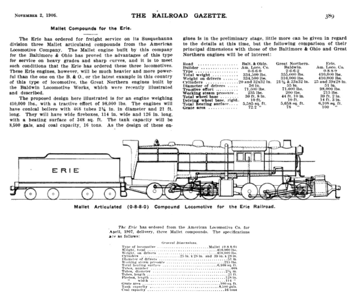 |
| added 08 January 2022 |
The Railroad Gazette, August 16, 1907 Delivery |
 |
| added 08 January 2022 |
|
Completion and Delivery
|
 |
|
added
08 January 2022
|
|
Completion and Delivery
|
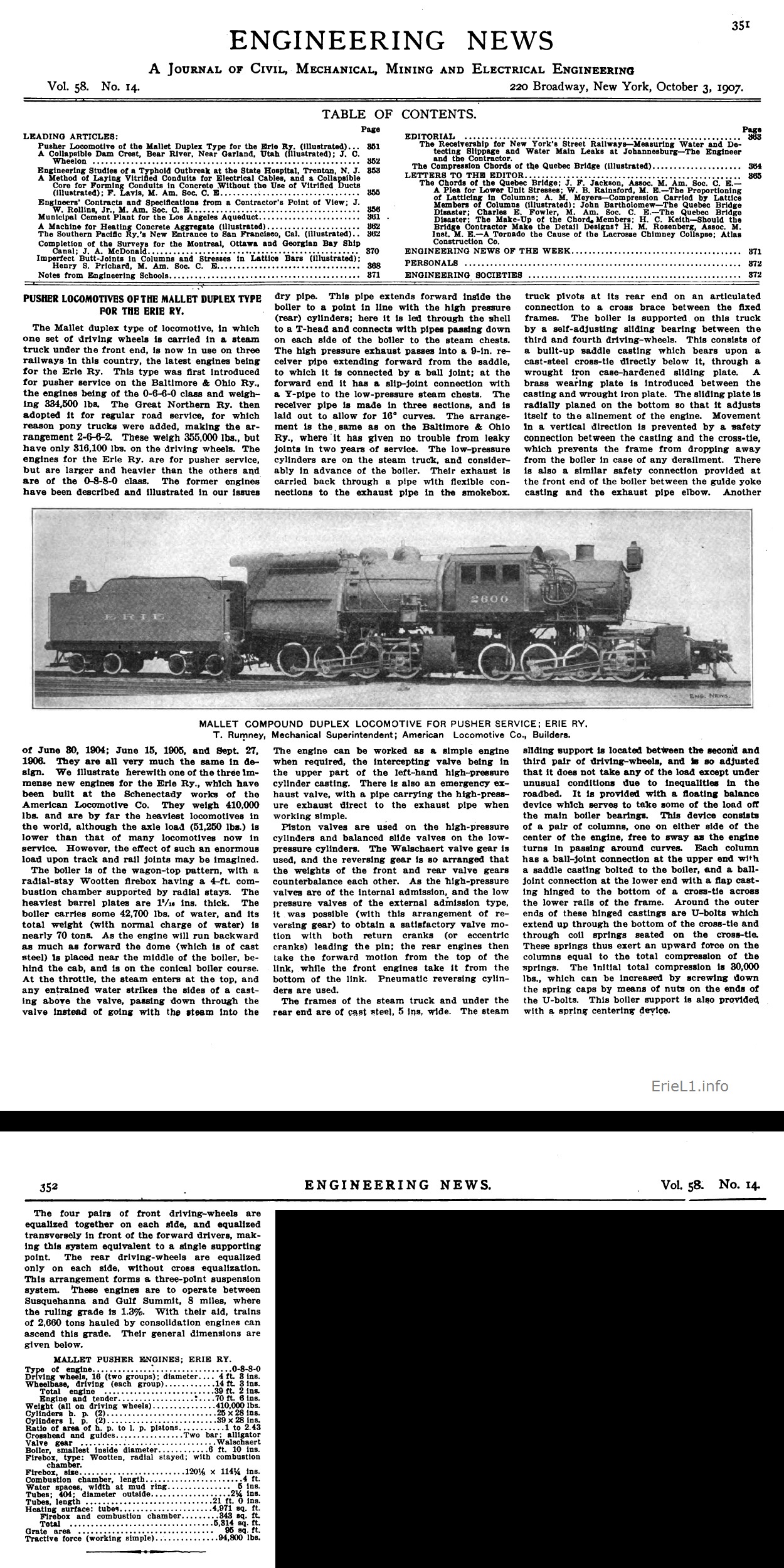 |
|
added
23 January 2022
|
 |
| American Engineer and Railroad Journal, June
1908 Dynamometer Car Testing and Results added 08 January 2022 |
 |
517. When ascending grades upon which pusher engines are used, the conductor is required to protect the rear of the train in the same manner as if there were no pushing engine. |
 |
 |
 |
Special
Instructions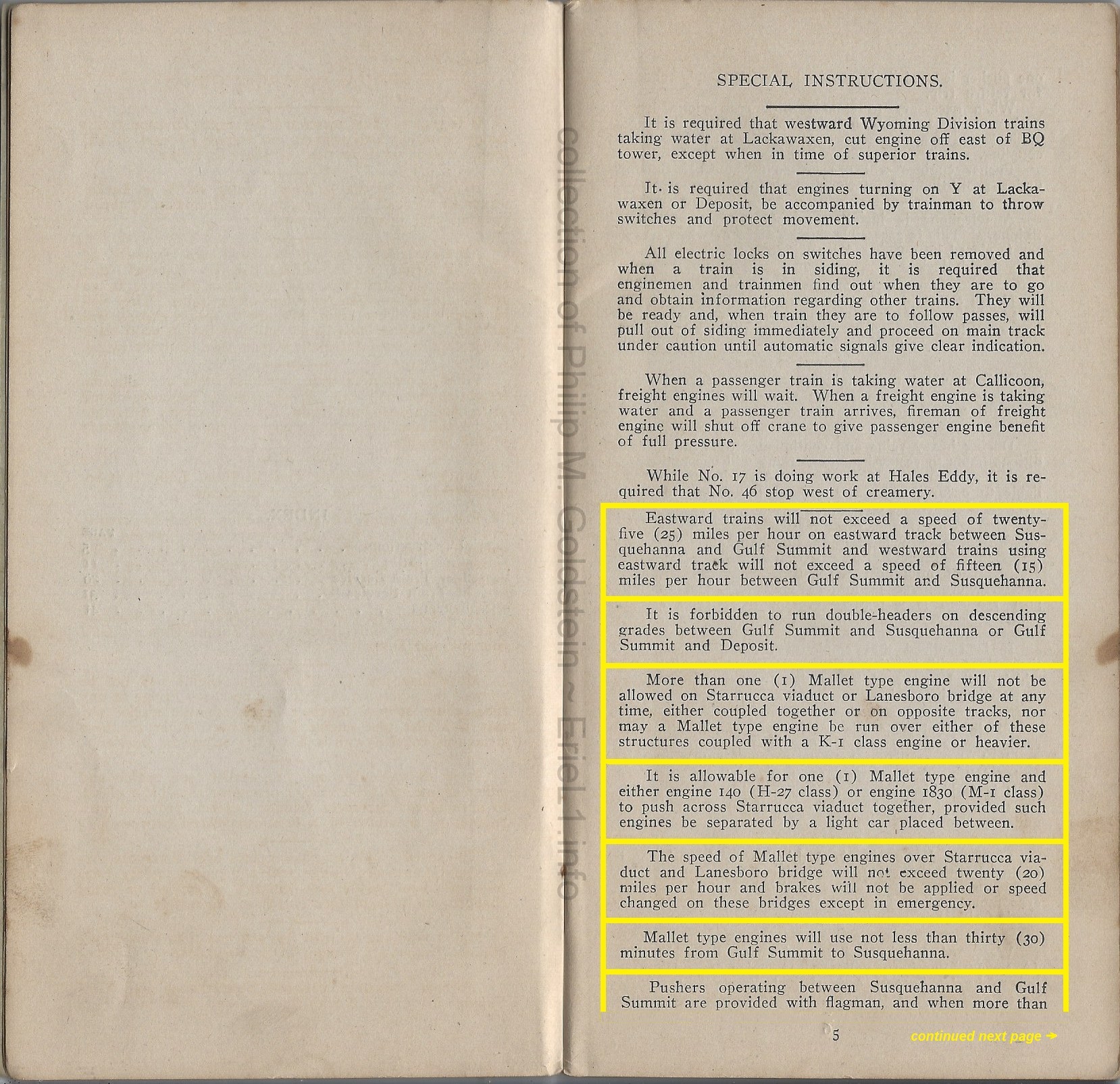
|
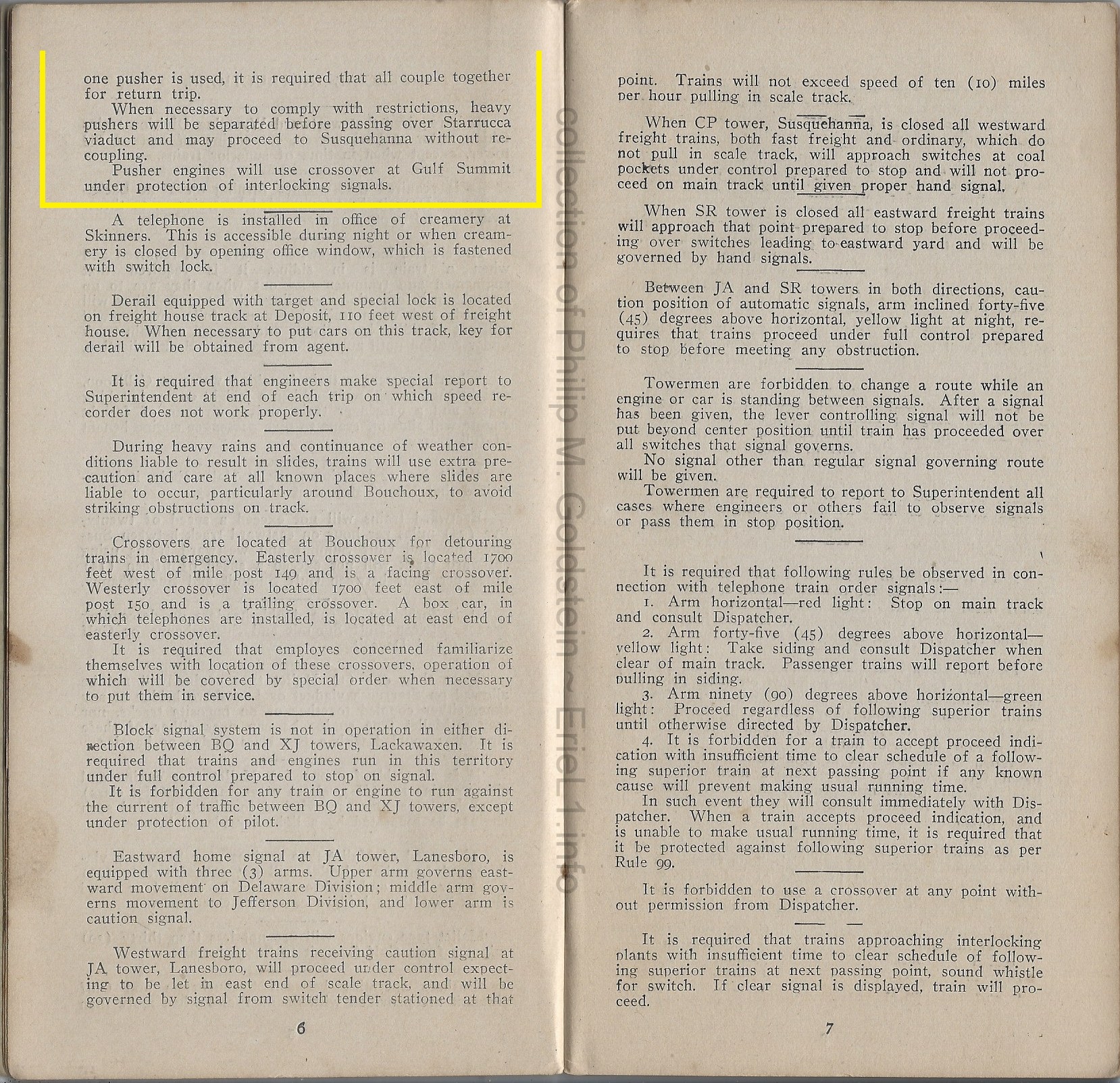
|
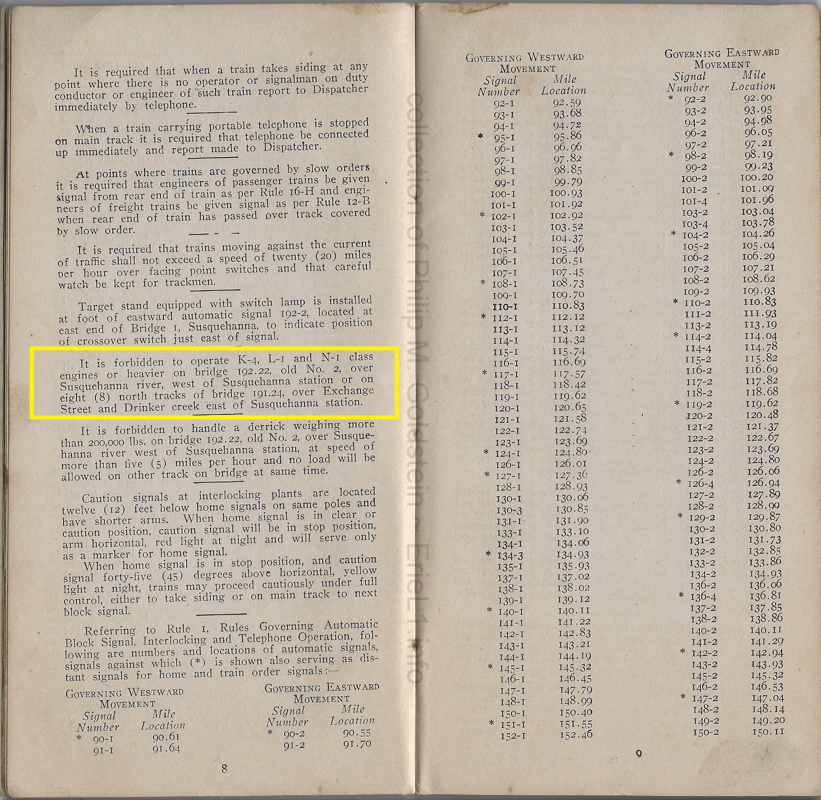
|
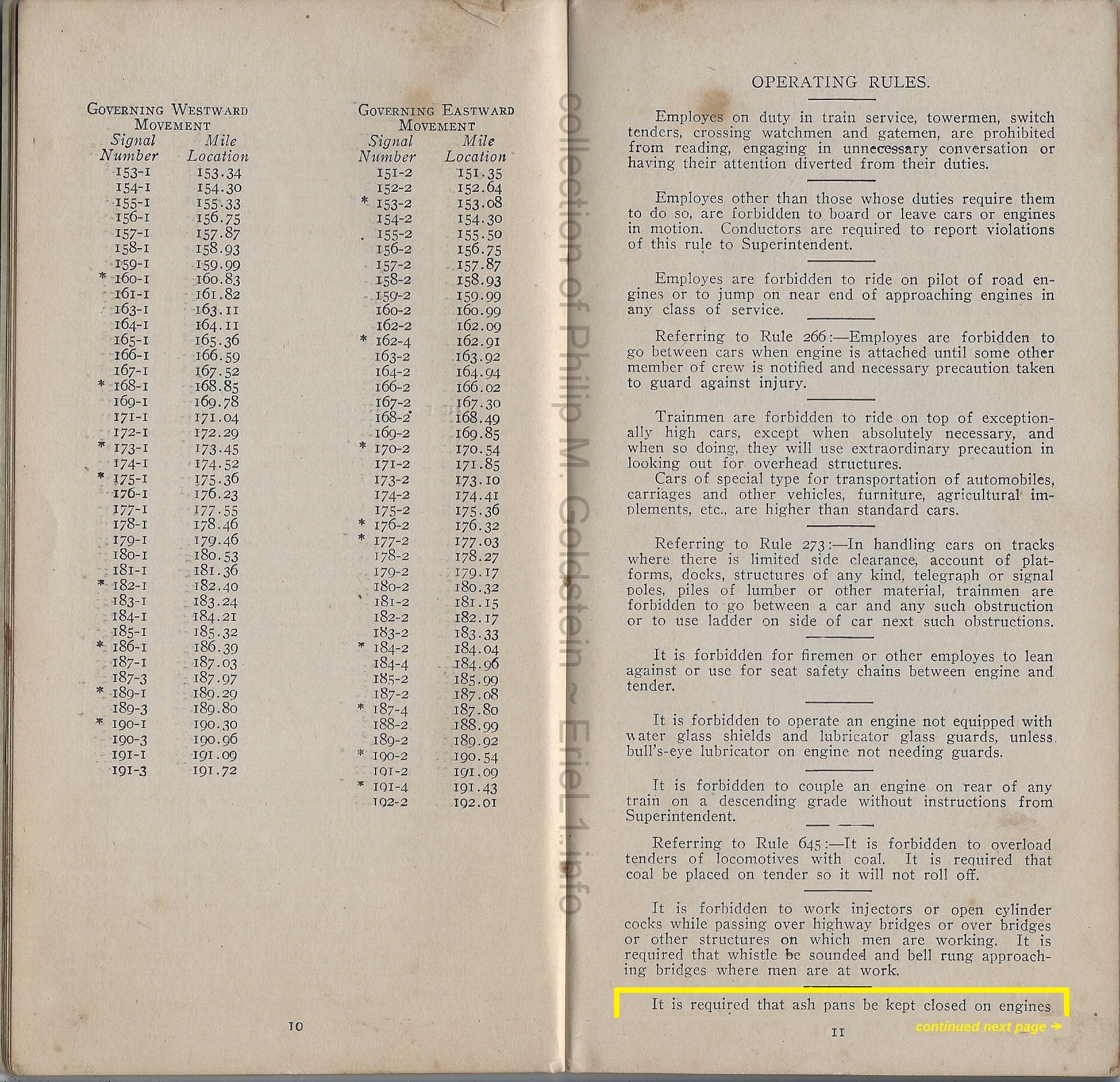 |
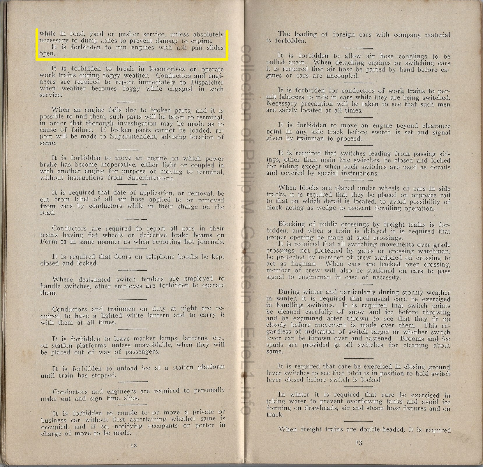
|
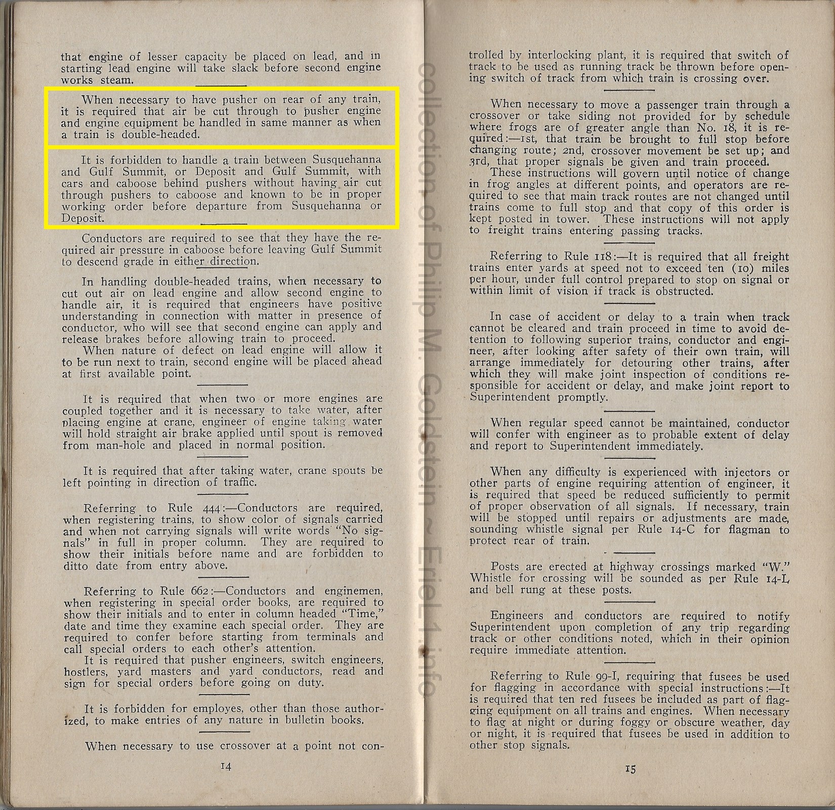
|
|
 |
Passenger
Train Service |
 |
 |
 |
 |
Freight
Train Service |
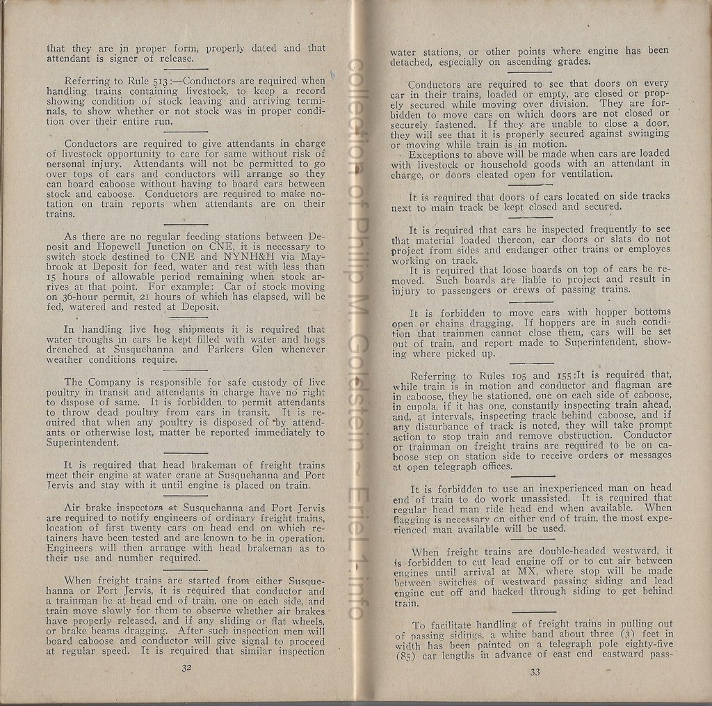 |
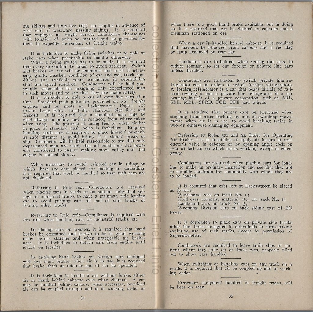 |
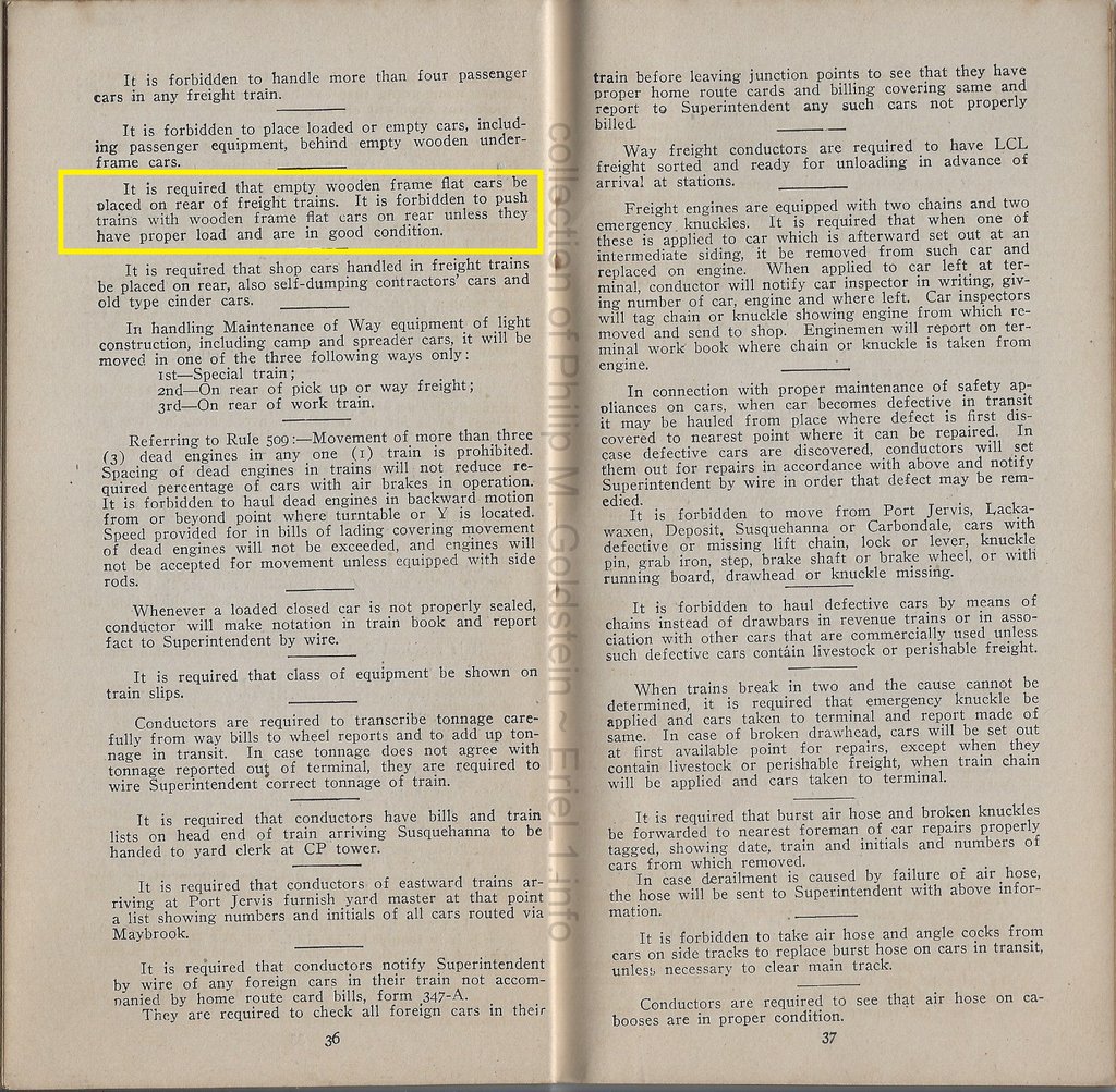
|
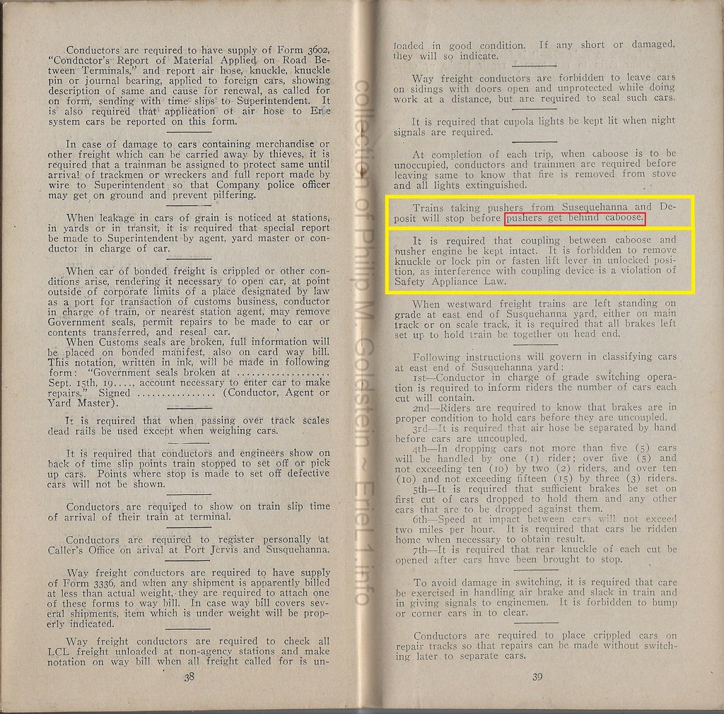
|
Miscellaneous
Rules |
 added 13 January 2013 |
 |
| . |
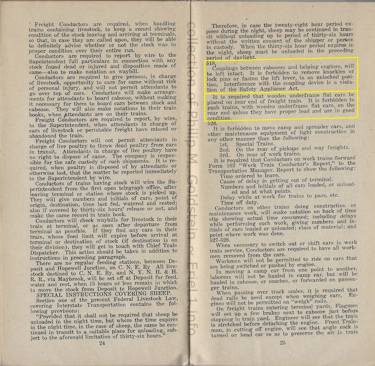 |
|
| . |
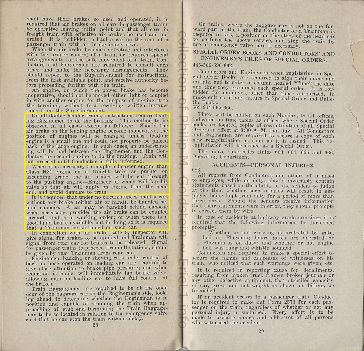 |
|
| . |
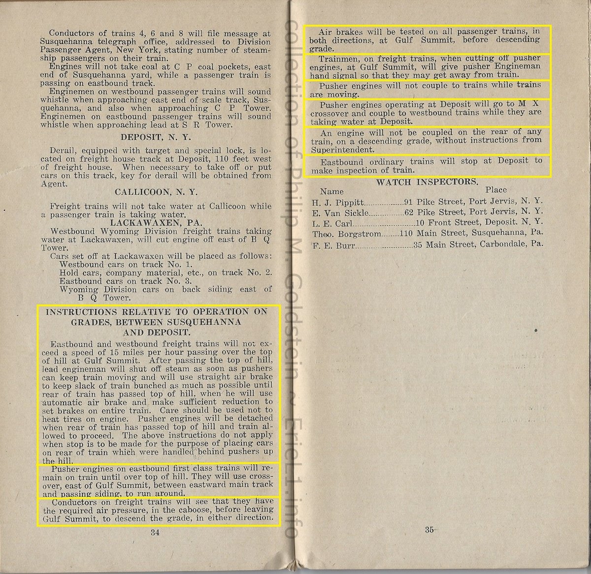 |
|
| added 26 January 2013 |
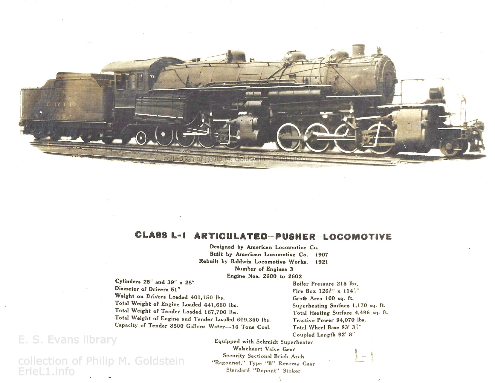
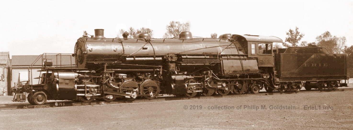
January 1, 1907 Agreement - Effective April 15, 1910; Supplemental December 1, 1910
Imagine if you will, my surprise when looking for rules or regulations on the placement of a caboose in conjunction with pusher locomotives; I happen across an arbitration filing for locomotive engineers for the Erie Railroad.
Further imagine my increased delight to see that the engineers of the L1's had their own specific pay rate; to the tune of $6.00 per day. Allowing for 22 work days per month, that comes to $132 per month.
It should be noted, that these Angus drivers were paid a flat rate for the day (equivalent to 60 cents an hour), and received pro-rated overtime pay after 12 hours of service,to be reduced to 10 hours of service in December 1910. This in comparison to other engineers who were putting in 12-16 hour days and getting paid 3.9 to 4.2 cents per mile.
The average work day for a L1 engineer was 10-12 hours. But
an L1 locomotive engineer
was not moving for all of the those 10-12 hours, so paying him by the
mile was not equitable.
Which
is why passenger engineers were paid
less per mile, as they accrued more mileage per shift. A passenger
engineer would have to travel 154 miles to equal the flat rate daily
pay of an Angus engineer.
Whereas freight engineers were paid more per mile as they had to wait for orders, signals, taking the siding to get out of the way of passenger trains, stopping for coaling and watering. Averaging 30 miles per hour on the Erie, multiplied by 8 hours equals 240 miles. 240 miles traveled multiplied by 4.2 cents per mile = $10.08. To equal the rate for Angus engineer, a freight engineer would have to travel 133 miles.
Yard engineers making 40½ cents per hour, would have to work almost 15 hours to equal the 12 hour pay of an Angus engineer.
But for Angus engineers; and at that point in time, $6.00 per day is not something to sneeze at either. Adjusting for inflation at the time of writing this in February 2022; that equates to $169 per day, $3,718 per month, or $44,616 per year.
Not bad considering one had set work shift hours, spent some of that time waiting for the freight train that needed help to arrive; never ventured far from home, and got to go home nights. And you were in charge of the largest locomotive in world.
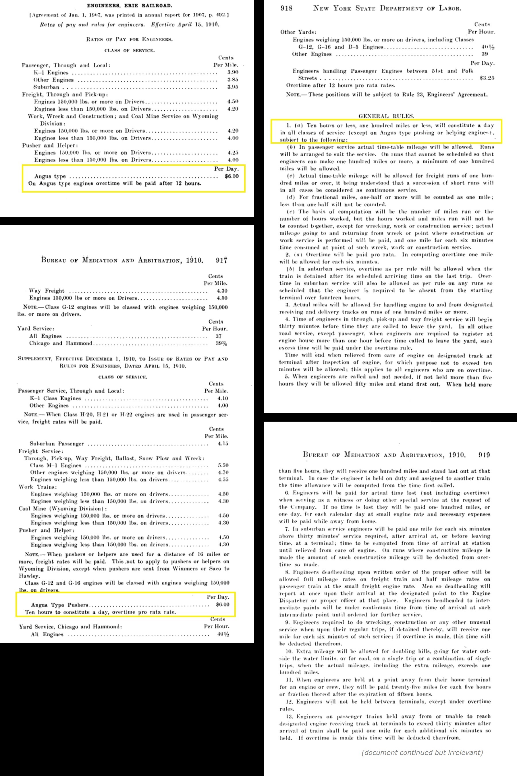
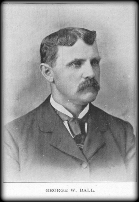
GEORGE W. BALL,
Susquehanna, Pennsylvania.
George W. Ball, son of Charles Ball, a mason and contractor of Honesdale, Pa., was born in that city April 23, 1853.
He was an industrious student in the public schools until he was 18 years of age, when, having acquired a good education, he cast about for means to earn a livelihood. The first opening he found was in the capacity of an oiler on the Gravity road for the Delaware & Hudson Coal Company, and he accepted the same, serving them faithfully for one year, when he resigned to take a position as brakeman on the Erie.
For six years he ran between Honesdale and Port Jervis and then was advanced to fireman. Eight years in this capacity fitted him to become an engineer, and in December, 1886, he was promoted to that responsible position. For nine years he ran an engine in the freight department on the Delaware Division, his work demonstrating his entire fitness for the place and winning him the approval of his superiors.
In
1895 he was given a pusher, which he runs between Susquehanna and Gulf
Summit, and he is better pleased with this run than with regular road
work.
On September 9, 1874, Mr. Ball was united in marriage to
Miss Ella Eggleston, daughter of Ensign Eggleston, proprietor of a
livery barn in Honesdale. Nine children have been born to them, two of
whom, Russell and Ruth, died when quite young. Grace, aged 24, is
married; Charles, 22, is a telegraph operator; Lulu, 20, and Mary, 19,
both accomplished young ladies, reside at home; James, aged 17, is an
apprentice in the Erie machine shop; Frank, ll, is attending school,
and Harold Ray, 6, is the baby of the family. Mrs. Ball is a member of
the Ladies' Auxiliary Lodge, B. of L. E., and a fine, motherly lady,
who takes great pride in her interesting family. Mr. Ball is a very
popular man, both among his fellow workmen and acquaintances generally.
He is a member of Starrucca Division of 137, B. of L.E.; Susquehanna
Lodge No. 246, Order of Red Men, and Canewacta Lodge No. 360,
F.&A.M.
Excerpted from: "American Locomotive
Engineers, Erie Railway Edition," H.R. Romans Editor; Crawford-Adsit
Company Publishers, Chicago, IL 1899.
George Ball, of Engine 2600 fame, absolutely refused to believe the new 5014 had anything on the "Big Ange", until one day he was assigned to the new machine. Now he is willing to trade even.
September, 1914 issue of Erie Railroad Magazine
Mr. George W. Ball, engineer, is back on the "Matt Shay" after several months' illness.
June, 1915 issue of Erie Railroad Magazine
From
the Susquehanna Transcript the death of George W. Ball is learned. It
stated that he died in St. Augustine, FL, where he went in search of
renewed health. He came to Susquehanna 25 years ago and was employed on
the Honesdale Branch. He had been formerly employed as engineer in the
pusher service out of Susquehanna, running on the Delaware Division for
a number of years.
January, 1924 issue of Erie Railroad Magazine
."I have a period silver gel yard long photograph of the 2600 that shows a lot of detail, unseen in the typical postcard sized views of this locomotive. The plate below the makers plate states that the owner and trustee of this locomotive at the time it was constructed was Edward T. Stotesbury, a partner at J. P. Morgan and railroad investor.
A quick Google search and several images of Edward can be found, which is without a doubt, the gentleman in the photo standing next to the engine. I have never found any references in any publication that links him to this engine other than in the details of the image I own."
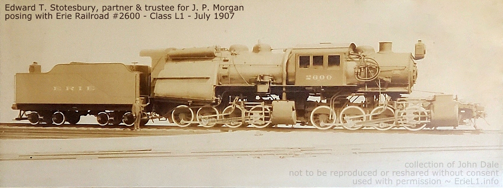 |
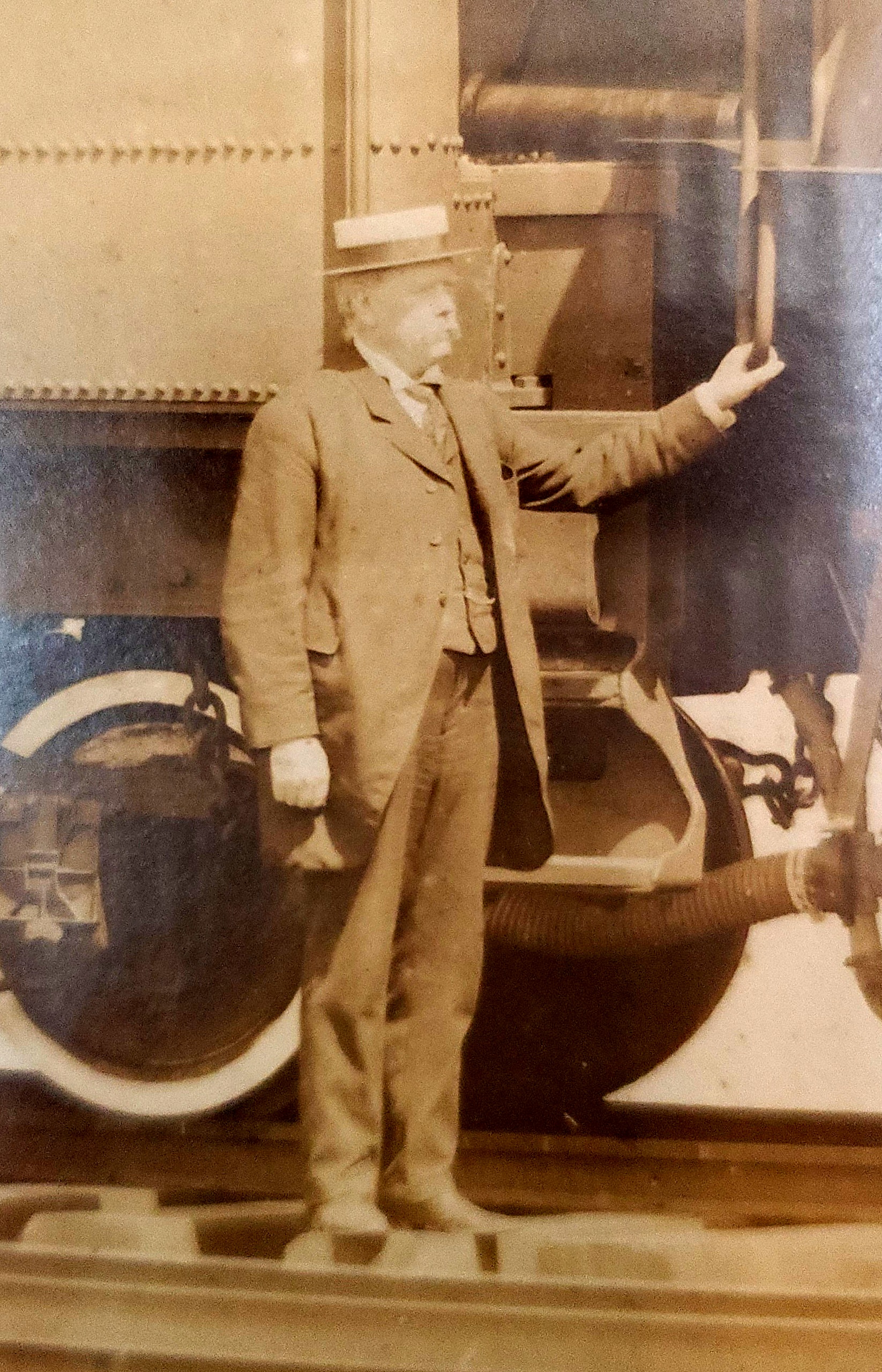 |
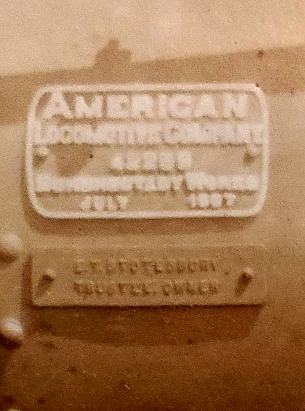 |
| Edward T. Stotesbury (standing by tender steps) |
American Locomotive Company 42269 builders
plate E. T. Stotesbury Trustee, Owner Plate |
Art, Advertising, Postcards & Images
..
.
|
|
|
| . . |
|
|
|
|
| . . |
|
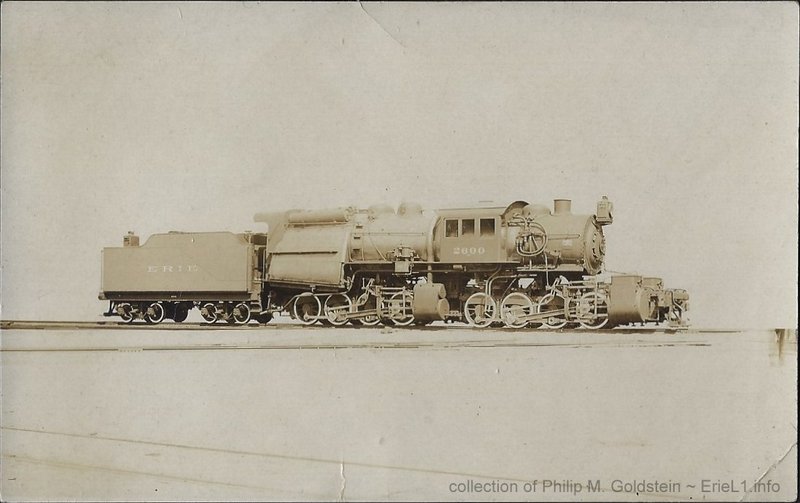 AZO Real Photo Post Card divided back postally unused authors collection |
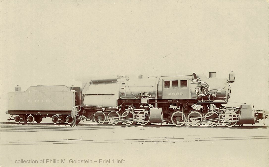 Locomotive Publishing Ltd., 3, Amen Corner, London, E.C., Real Photo Post Card note this card has person posing by tender steps (believed to be E. T. Stotesbury, trustee - see large photo in Stotesbury chapter) undivided back postally unused authors collection |
| . | |
|
|
|
| . | |
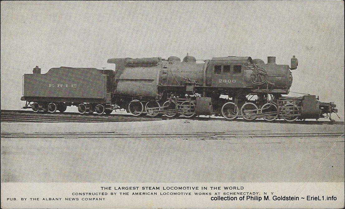 pub. by Albany News Company divided back postally unused authors collection |
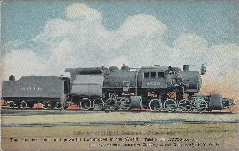 Hugh C. Leighton, Portland, ME #27053 Made in Germany divided back postally unused authors collection |
| . | |
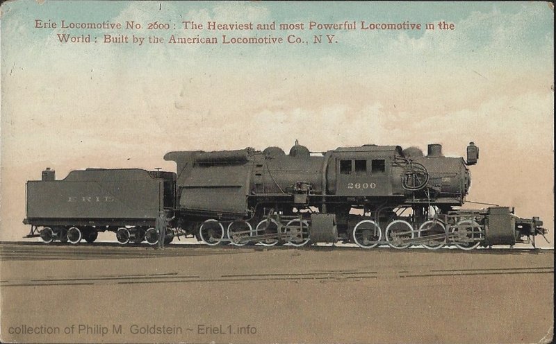 The Valentine & Sons Publishing Co, Ltd. New York printed in Great Britain divided back postmarked Matamoras, PA - August 19, 1910 authors collection |
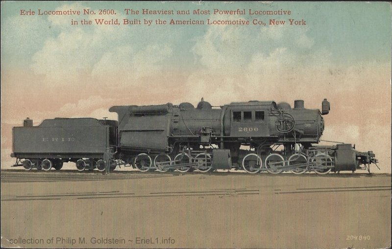 Leighton & Valentine Co, N. Y. City. #204840 Printing in United States divided back postally unused authors collection |
| . | |
|
|
|
| . | |
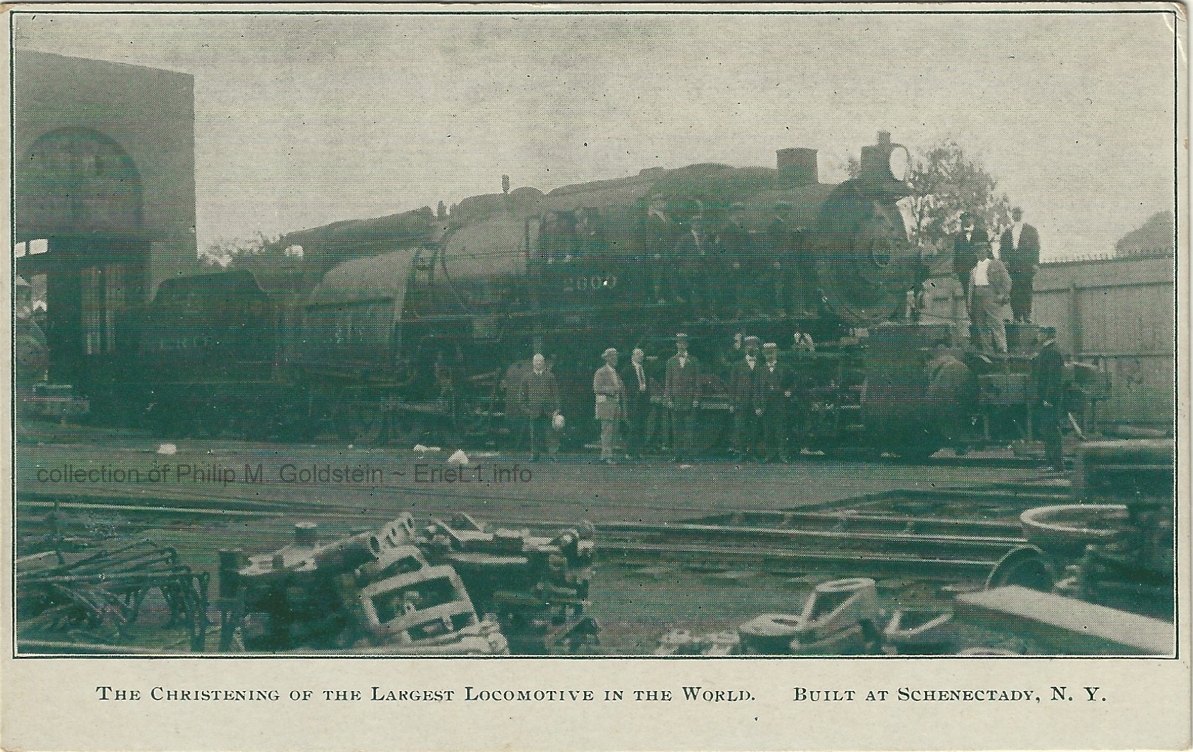 Published by J. J. Cunningham, Schenectady, NY undivided back addressed but postally unused authors collection |
intentionally left blank |
| . | |
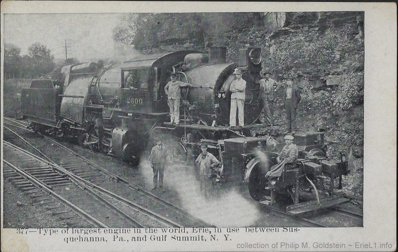 Herald Post Cards, Hallstead, PA divided back postally unused authors collection |
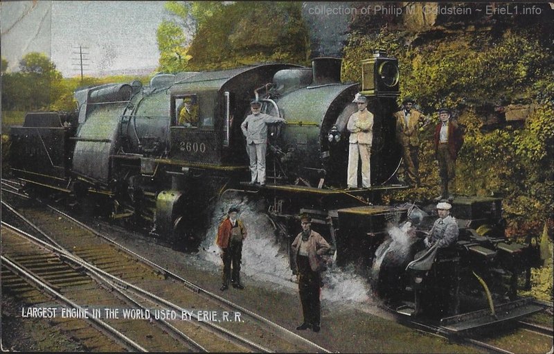 Baker Brothers Elmira, N.Y. #2123 divided back - printed in Germany postally unused authors collection |
| . | |
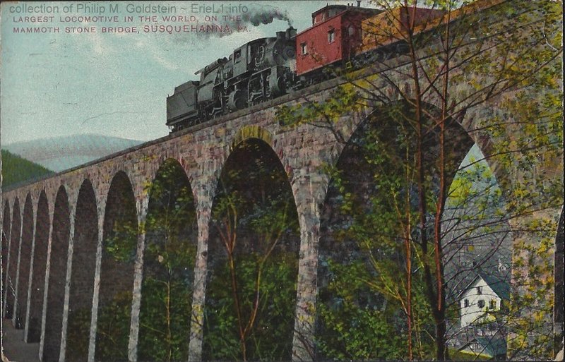 No. 2600 Art Tone Series by C. D. Burton, Lanesboro, PA divided back - printed in Germany postmarked Susquehanna, PA - July 21, 1910 authors collection |
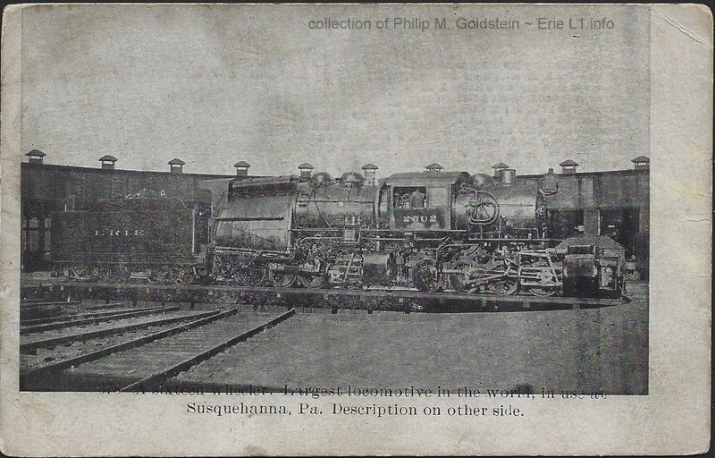 Herald Post Cards, Hallstead, PA divided back postally unused authors collection |
| . . |
|
 Christening of #2600 - July 1907 American Locomotive Company, Schenectady, NY All I can say about this image is "wow." One of the highest resolution digital prints I have ever encountered (or purchased), and historically significant. In this image we have easily identifiable persons of both the Erie Railroad and American Locomotive Co, christening Locomotive #2600: Angus Sinclair
Bent
over, breaking a bottle of champagne on the top of the cylinder (note
foil wrapped neck of bottle in hand). Sinclair was a Erie
Railroad special
instructor, locomotive engineering, and publisher of "Railway &
Locomotive Engineering" technical journal. Sinclair's
other "contribution" to the Erie L1, was that he is believed to have
stated before the L1's were completed, that the L1 would "dry up the
country's canals and make water transportation obsolete". While
this was clearly hyperbole, it is understood that the Erie RR saw fit
to honor this statement by assigning Sinclairs' name to the class of
locomotive: "Angus" Carl J. Mellin
Supervising
engineer for American Locomotive Company when the Erie L1's were
designed and built, and he developed and patented the specific compound
cylinder system used on the Erie L1 design.Edward T. Stotesbury
Owner
and trustee of this locomotive at the time it was constructed.
Stotesbury was a partner at J. P. Morgan and railroad investor.Fredrick D. Underwood
President, Erie Railroad (with rolled
umbrella)
T. Rumney
Mechanical Superintendent, American
Locomotive (formerly Master Mechanic, Erie RR)I would also like to identify
other gentlemen in the image, so if you can furnish identification,
please contact me at bedt14@aol.com
I even located the following description accompanying the image:
not to be reused or reproduced without consent. added 25 October 2024 |
|
| . . |
|
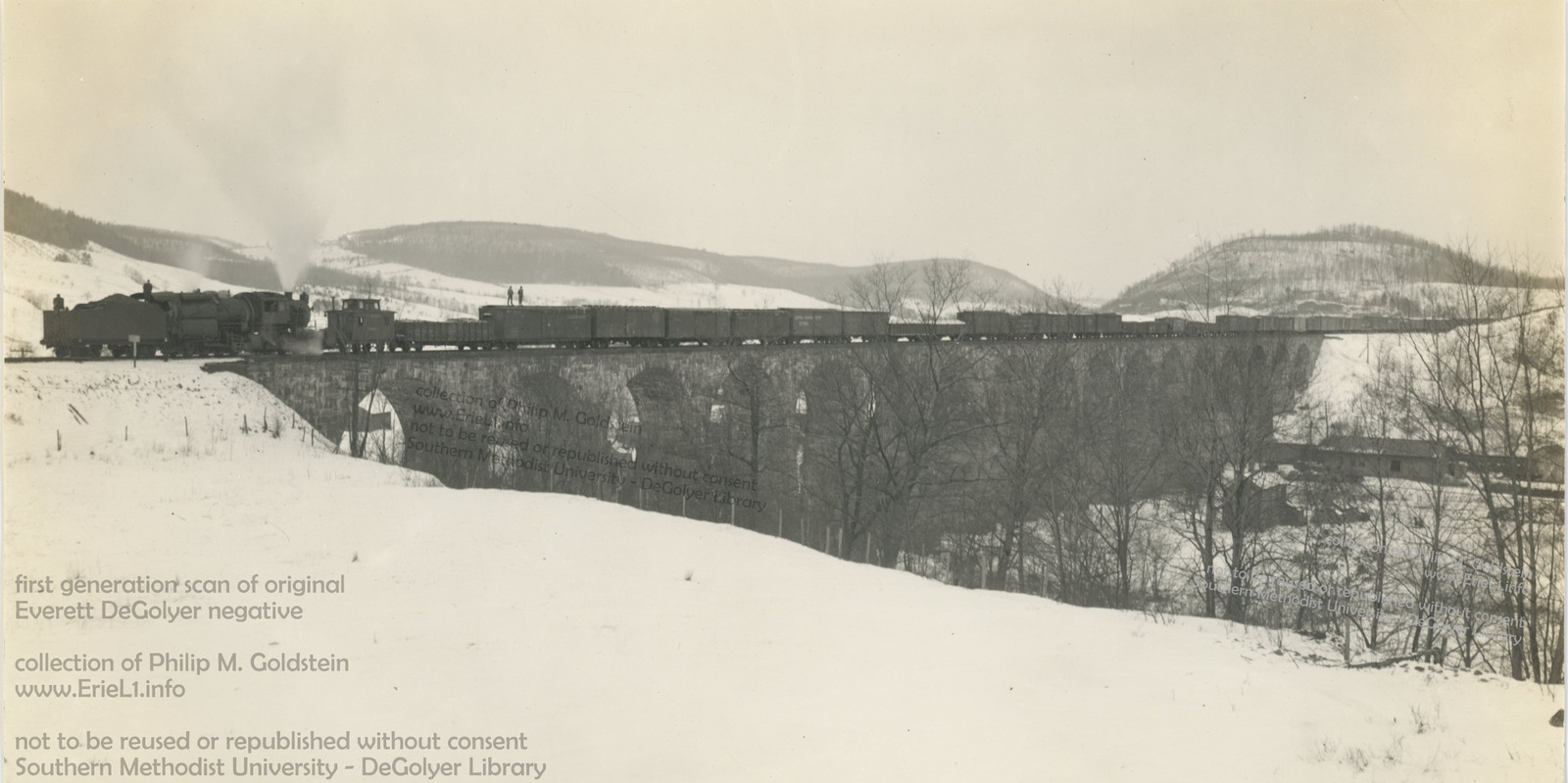 Starrucca Viaduct - unknown date
This image is a first generation high resolution scan of Everett DeGolyer's original negative. crop and zoom below. authors collection Southern Methodist University - DeGolyer Library not to be reused or reproduced without SMU consent. added 28 February 2022 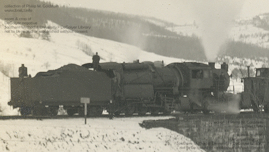 Note the marker lamp to right of tender light and on tender tank. The placement of a red flag or red marker light was specified to be placed on the rear of tender when locomotive was pushing. This was so ordered in the rule books. Locomotive is definitely pushing. |
|
| . . |
|
|
|
|
| . . |
|
|
.
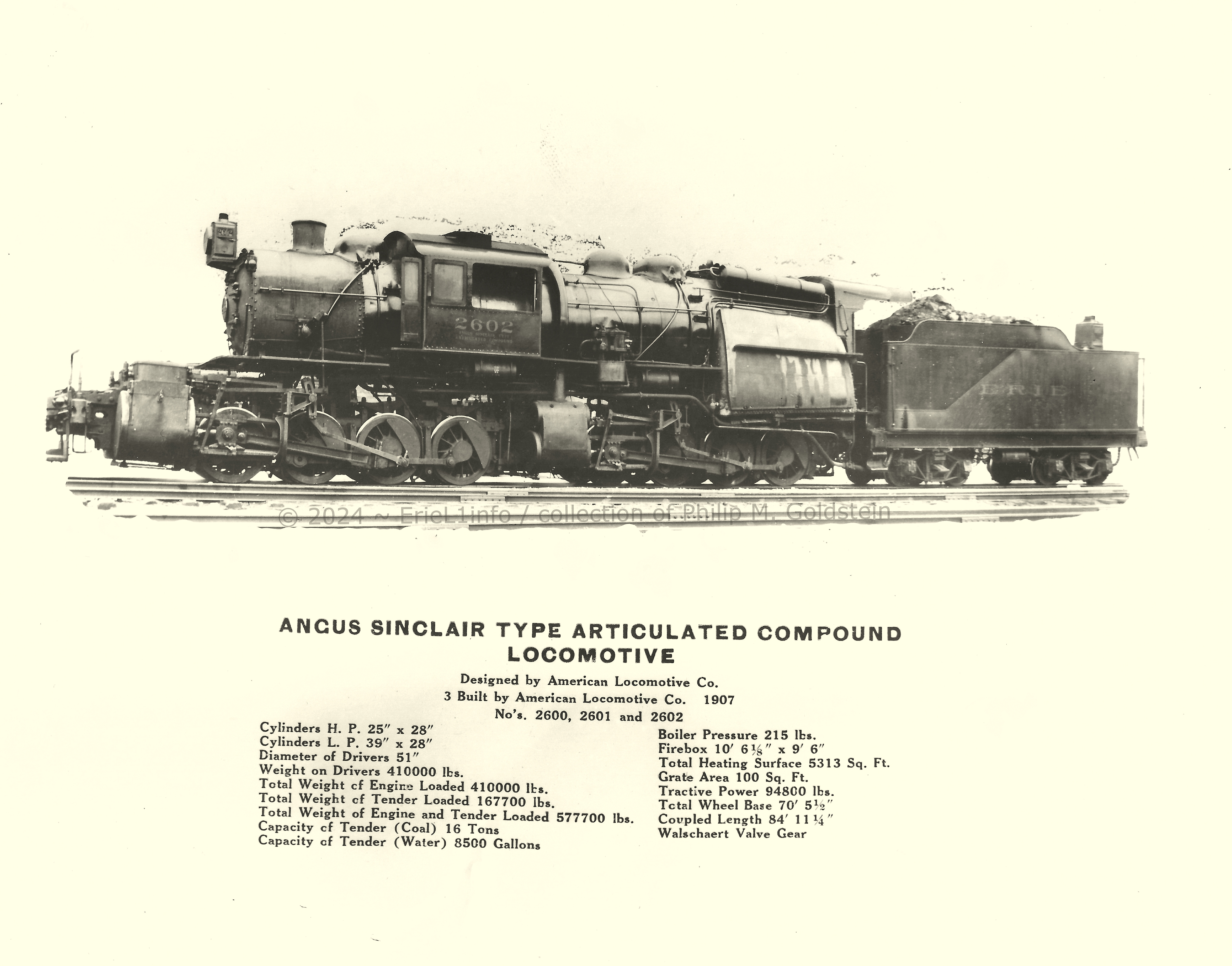 #2601 - builders photo?
E. S. Evans, Jr. collection authors collection added 31 October 2024 |
|
| . . |
|
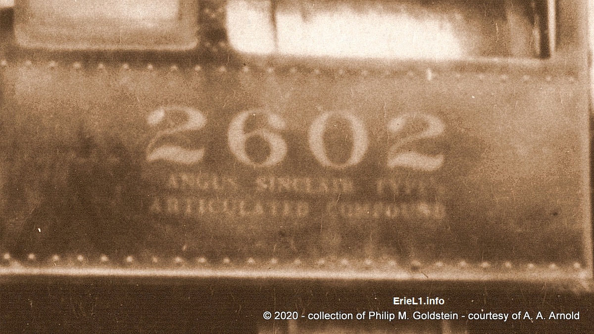 enlargement of cab writing: 2602 ANGUS SINCLAIR TYPE ARTICULATED COMPOUND |
|
| . . |
|
|
|
|
| . . |
|
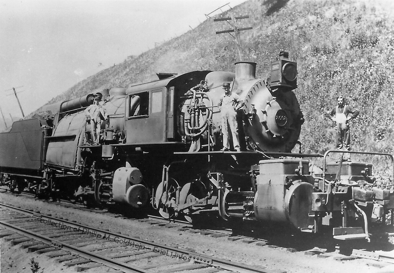 #2602 - unknown location (believed to be Gulf Summit, NY) - 1915 unknown photographer stamp on back of photo: C. T. Andrews, 4231 S. W. 38th St. W. Hollywood, Fla. this first generation darkroom print is identical to the image in Alexander's book, therefore it appears to have been commercially produced. |
|
| . . |
|
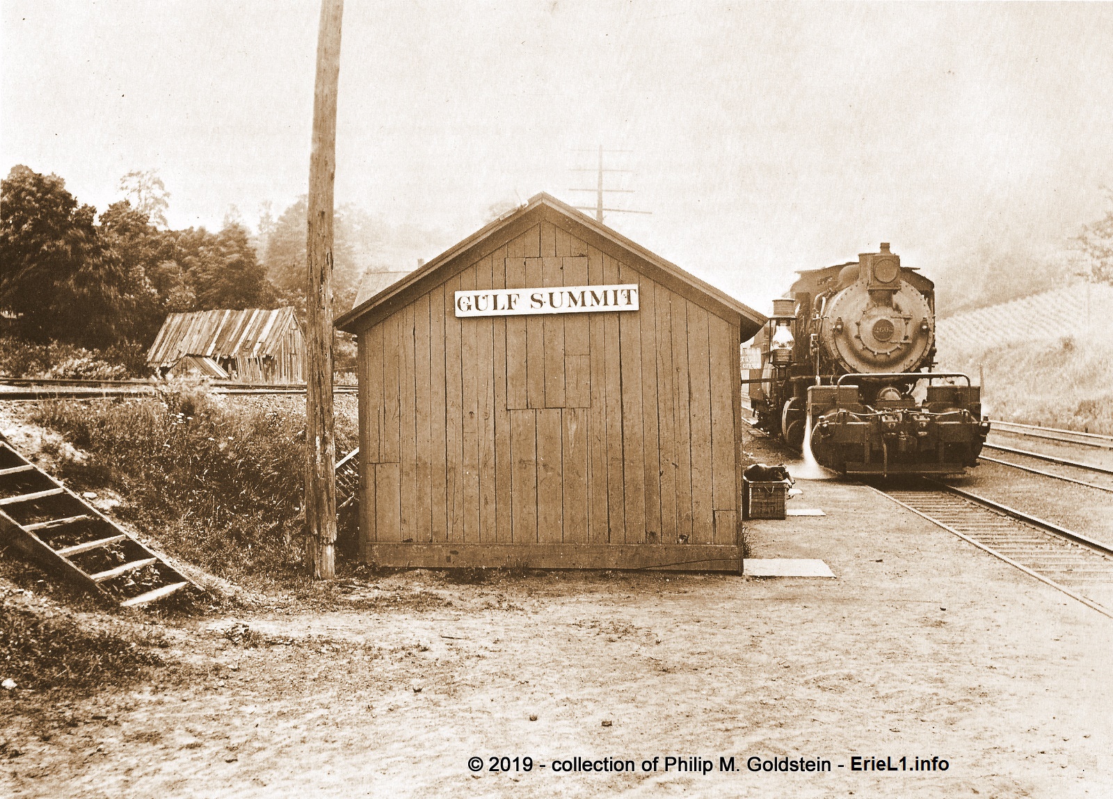 #2602 - unknown date - Gulf Summit, PA - unknown photographer from the 1979 Erie Railfan Calendar authors collection added 2021 |
|
| . . |
|
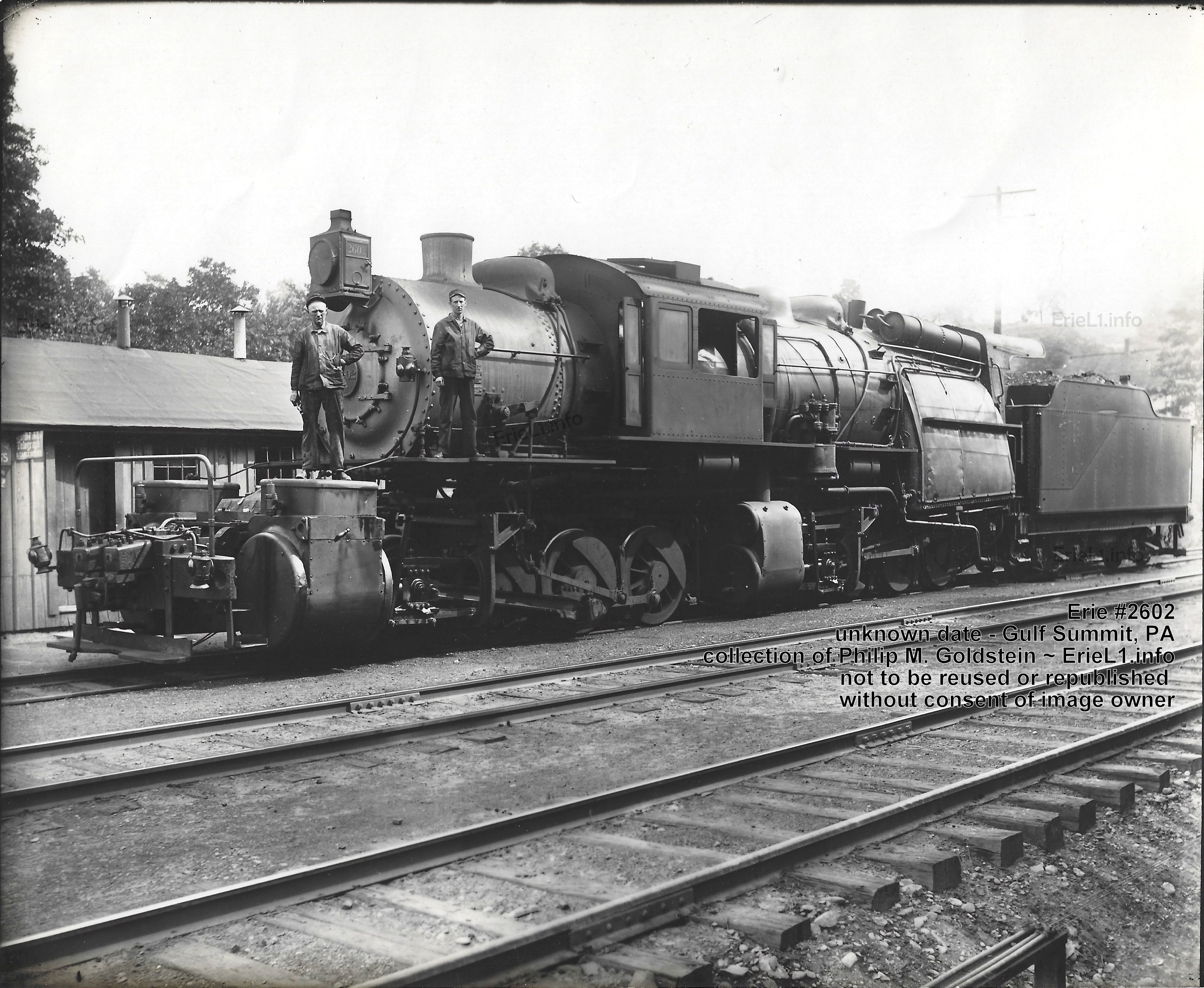 |
|
| #2602 - unknown date -
Gulf Summit, PA - unknown photographer This particular image is quite an exciting addition to my collection. Just when you think all that is already out there is all that exists, something new turns up. It is a dark room print from a glass plate negative and this particular image has been unknown until now, as I never seen it published in any historical accounts, industrial journals or railfan books or websites. The back of the image is marked: New Jersey Industrial Photographers - P. O. Box 64, Carlstadt, NY 07072 authors collection added 27 April 2023 |
|
| . . |
|
|
|
|
| . . |
|
|
|
|
| . . |
|
|
|
|
| . . |
|
|
|
|
| . . |
|
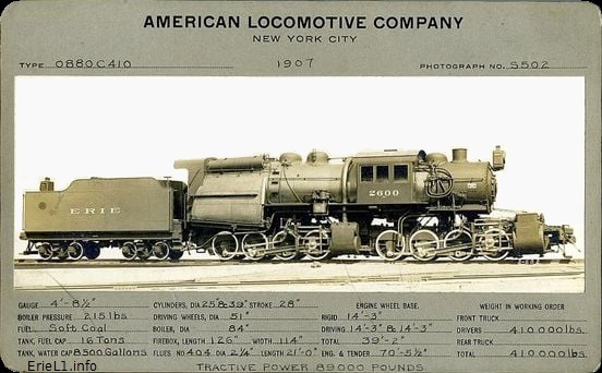 |
|
| American Locomotive
Builders Card for 0880 C410 Type - Erie L1 class of particular note is the listing under "fuel": soft coal. Thanks to the Cullen / Gridley Thesis of 1908, we can now confirm that bituminous coal was used in the Erie L1's. image from internet added 01 January 2022 |
|
| . . |
|
|
|
|
| . . |
|
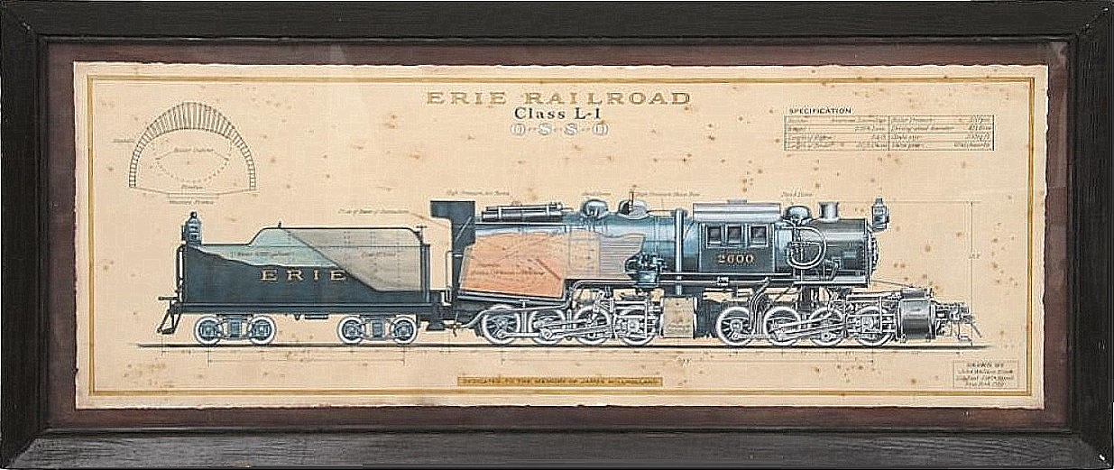 |
|
| This painting sold at
a recent auction (NOT eBay) and as my luck would have it, a year before
I located it. It was painted by John Wallace Elder, a professional artist who lived from 1872 through 1954, and created many detailed paintings of locomotives. The drawing is dedicated to the memory of James Millholland (1812–1875). Millholland was an American railway master mechanic who is particularly well known for his invention of many railway mechanisms. Millholland's inventions and contributions include the cast-iron crank axle, wooden spring, plate girder bridge, poppet throttle, anthracite firebox, water grate, drop frame, and steel tires. He was also an early user and advocate of the superheater, the feedwater heater, and the injector. Several of his innovations were adopted as standard practice by the railroad industry. Dimensions of the painting are 20 1/2" tall x 56 1/2" wide. Estimated sale price: $1,500 to $2,500. Closing price: $1,400 plus buyers premium of 26%, and shipping. As I stated, I found this item after the auction took place and closed; but I would have loved to at least partaken in the quest to own it personally. That being said, I respectfully request that the fortunate person who does now own it would be kind enough to furnish better images of it, for inclusion here. It would be most sincerely appreciated, and if you so wish to be recognized - your name listed here as well. image from internet added 01 January 2022 |
|
| . . |
|
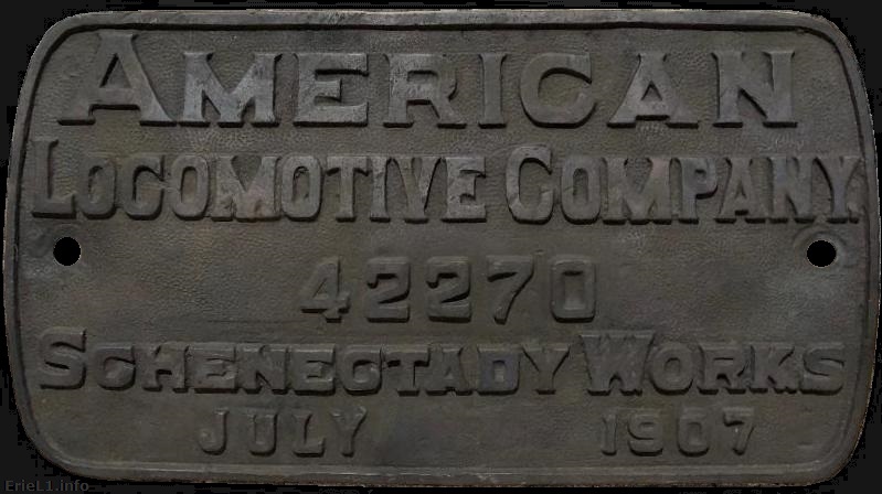 This ladies and gentlemen, is the real deal. Sent to me by a fan of this website and of whom owns this astounding artifact. This image was offered to be shared here, but the owner wishes to remain anonymous and I will honor his wish; on the proviso that if and when the time comes, and this thing of beauty needs a new home; that I be thought of. The line forms behind me! added 11 January 2022 |
|
Firemans
Canopy
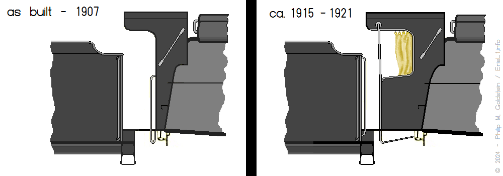
.
Modeling
..
Way back when I was 12 or 13, the family and I made one of our annual jaunts to Strasburg, PA. I went to the National Toy Train Museum there and much to my shock, there was a brass model of an Erie L1 in HO Scale on display.
Despite my asking in my local hobby shop, I was never able to
ascertain who manufactured it or where to purchase one (not that I
figured I could afford one anyhow!)
Lapse forward
30 years, the advent of the internet and advancements in model making
and tooling (and cheaper Asian labor forces!) saw new L1 models being
released in limited runs and the advertising to see they sold well.
There are now quite a few commercially produced scale models of this class of locomotive in both HO and O (2 and 3 rail) Scale, and in different configurations: as built 1907, and post-1915 (electric head light middle of smokebox, longer firemans canopy)
| distributor | manufacturer | item number | scale | material | issue era | prices seen | notes |
| NJ Custom Brass | Daiyoung | ST 222 / ST 227 | HO | brass | ca. 1970's? | $1750 - 2095 | |
| Overland | Ajin Precision | OMI 1548.1 | HO | brass | 1993 | $3500 - 3900 | post 1915 headlights, firemans canopy |
| Sunset / 3rd Rail Models | (Korea) | O (2 rail) | brass | 5/2001 | |||
| Sunset / 3rd Rail Models | (Korea) | O (3 rail) | brass | 2001 | $899-1600 | only 170 issued | |
| MTH - (Russian Iron) #2600 | (China) | 20-3852-1 | O (3 rail) | die cast | 2023 | $1600 | locomotive only |
| MTH - (Russian Iron) #2601 | (China) | 20-3118-1 | O (3 rail) | die cast | 2005 | $1300 | locomotive only |
| MTH - (Black) #2601 | (China) | 20-3853-1 | O (3 rail) | die cast | 2023 | $1600 | locomotive only |
| MTH - (Russian Iron) #2602 | (China) | 20-3441-1 | O (3 rail) | die cast | 2005 | $1399 | locomotive, 5 hoppers & caboose set |
| MTH - (Russian Iron) #2602 | (China) | 20-3854-1 | O (3 rail) | die cast | 2023 | $1600 | locomotive only |
| MTH - (Black) #2601 | (China) | 20-3442-1 | O (3 rail) | die cast | 2005, 2023 | $1399 | locomotive, 5 hoppers & caboose set |
.
(And if anyone out there has a non-operating, damaged, or
burned
out HO and / or O scale model they are willing to sell, please
email me.
All I desire are models for static display.)
.
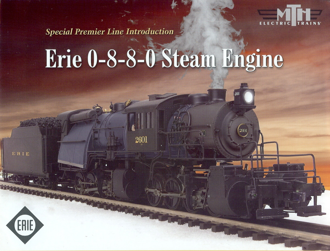

Front Cover & Inside of MTH Electric Trains for Erie 0-8-8-0
Item #20-3118-1
.
But alas, all of these commercial releases are cost prohibitive for a casual modeler like myself to own especially as a teen. The brass models then ran in excess of $700, and the O scale ready to run now sell in excess of $1400 retail.
So, I scratchbuilt my own.
.
30.1: Scratchbuilding my own L1
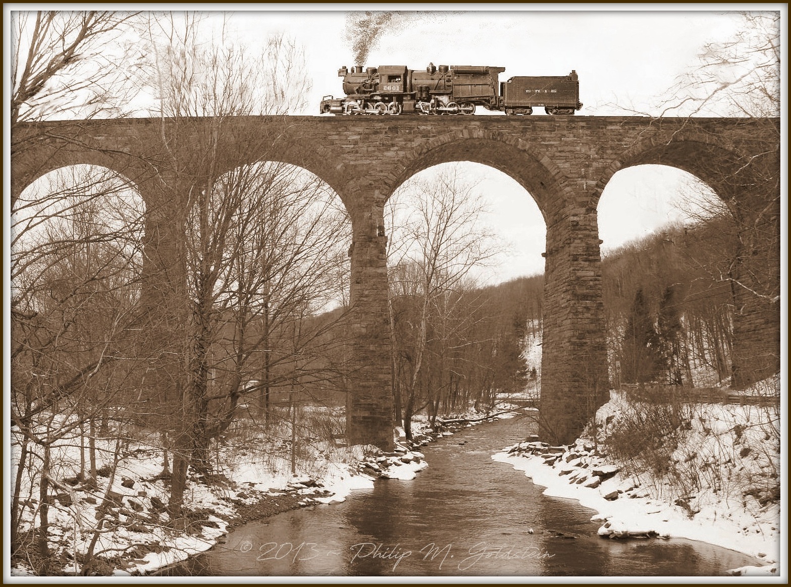
Yes,
it's photoshopped!
How else would I have been able to get an Erie L1 on
Starrucca Viaduct for the first time in almost 100 years?
My scratchbuilt HO scale model superimposed on a photo I took of the
real Starrucca Viaduct in 2012.
I am not the first to scratchbuild an Erie L1; as evidenced by an article by Bill Schopp in the February 1955 issue if Railroad Model Craftsman shows:
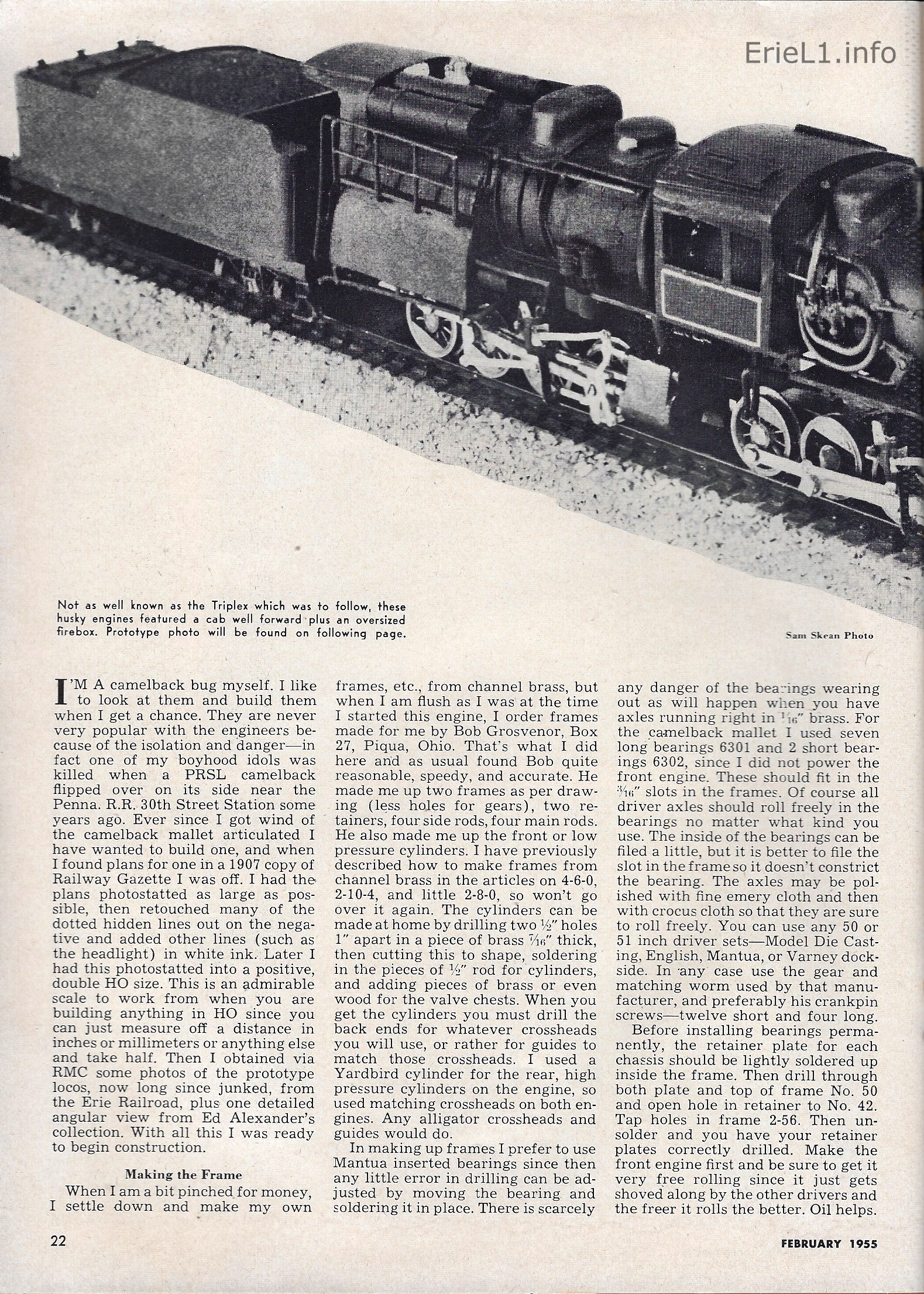 |
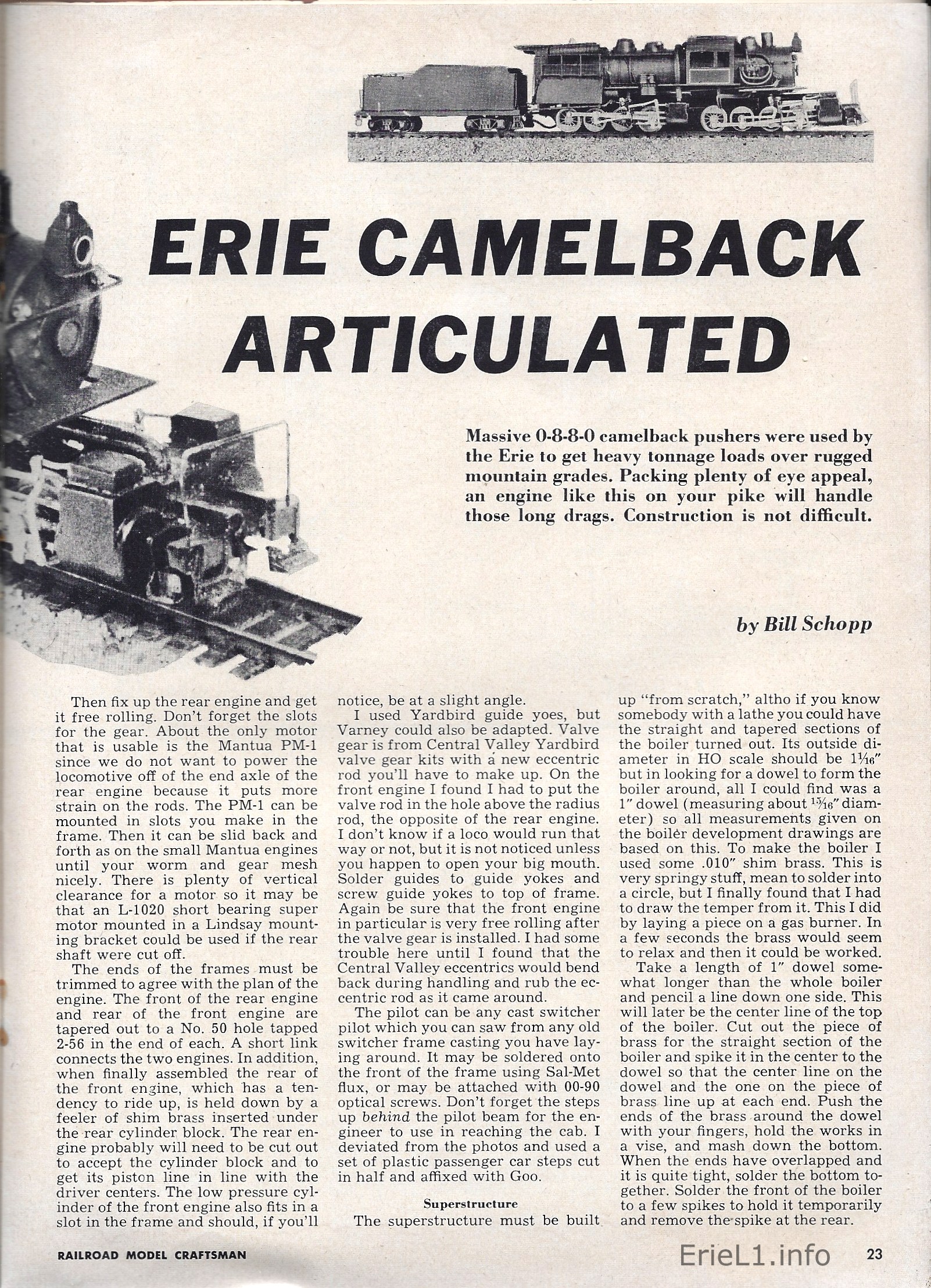 |
| . | |
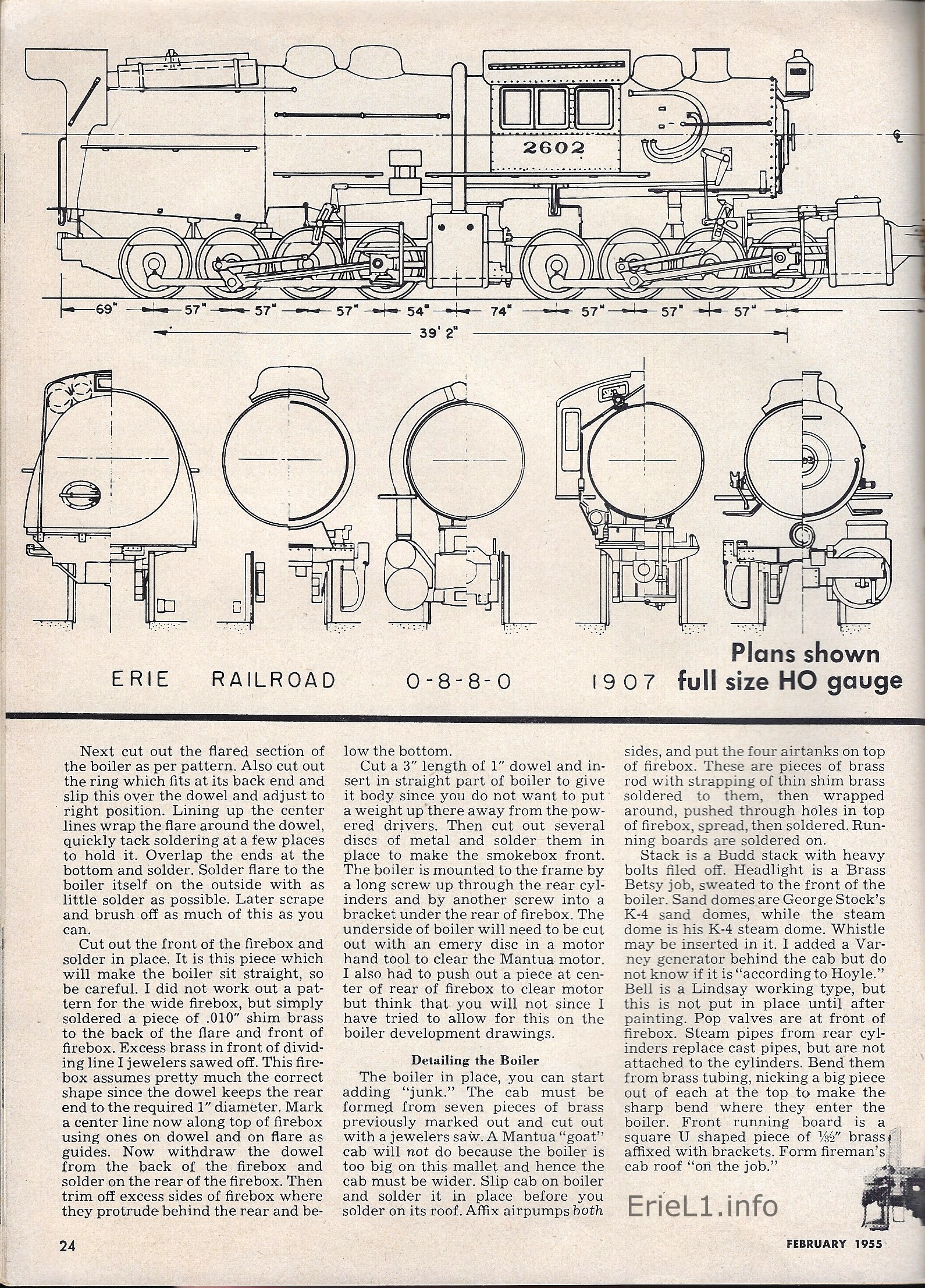 |
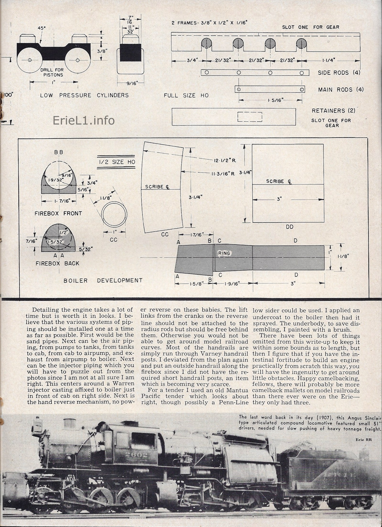 |
| Railroad Model
Craftsman (Carstens Publishing) - Volume 23, No. 9,
February 1955 authors collection added 13 January 2013 rescanned 22 January 2022 |
|
My scratchbuilding the Erie L1 would be my third attempt at scratchbuilding any locomotive in any scale. My first "scratchbuilding" attempt (re: cobbing) being a non-prototype RS2 short hood shop switcher on a B chassis; my second attempt being a 0-6-0T BEDT #16 in HO scale (requiring a scratchbuilt saddletank) which came out rather well; and I already had modified ready-to-run locomotives into either BEDT #14 and #15 or converted a rear cab PRR locomotive to a Camelback 4-4-2 Atlantic.
While I am particularly critical of my own creations - I have no patience painting, but will spend hours custom fabricating or modifying frames;, I am quite proud of this attempt.
.
The locomotive started as an undecorated Mantua HO scale 2-6-6-2 logging loco (catalog #334) and the tender is from the Mantua 4-4-2 #460 "Lindbergh Special" (catalog #460) or PRR #7002 (catalog #336) locomotives (as well as used by other locomotives in the catalog). This tender closely conforms to the silhouette of the tenders used with the L1's.
I purchased super-detailing parts (valves, boiler plugs, handrail standoffs from various vendors in Walthers Catalog and through local fellow modeler Frank Bell as well as Mantua. Frank was also generous enough to lend me his copy of Al Staufer's "Erie Power", and somewhere along the line I had located and acquired HO scale drawings of the Erie L1 class in one of the railroad modeler magazines. At the time, I did not know they were from the February 1955 issue of Railroad Model Craftsman (Carstens Publishing)... Now I do!
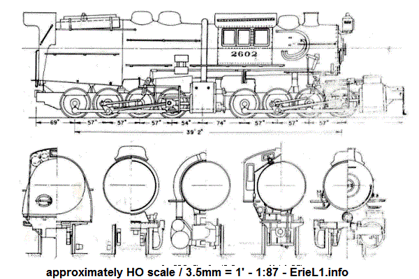
.
The cab is an "as molded" from Mantua, as are the domes and front headlight (which I know is incorrect). Front cylinders are Mantua castings from the 2-6-6-2T Booth Kelly logger, (catalog #326) while rear cylinders were original to this model. Hoses and piping are custom bent brass rod and various diameter solder. The live steam crossover is large diameter solder with heat shrink tubing. The valve in front of the cab is a custom hand filed piece of solder. The reversing bell crank is styrene and bronze phosphor wire, as are the handrails. The firebox is from the shell of a Mantua camelback locomotive (although I can't recall which one though, either a 4-6-2 or 2-8-2). The boiler in front of the cab is from the same Mantua kit. The section of boiler between the firebox and cab is heated and bent styrene sheet, as are the running boards.
The frames are Mantua zamac castings for the 2-6-6-2 locomotive (three axles per frame), which as it turned out driver diameter and axle spacing was close enough to satisfy my needs and I think both were only off by a few scale inches). As I required a four axle per frame arrangement for my 0-8-8-0, I purchased four frames (two front, two rear) from Mantua and proceeded cut the first two of the three axles off the rear frames and the last two of the three axles on the front frames, making a total of four two axle half frames. Then placing them in a jig, I scored the parts with guide lines for alignment, measuring axle spacing, and proceeded to file the mating surfaces with a jewelers file. I bored holes lengthwise on the cut ends of the four pieces, and using solid brass rod as alignment pins and a dot of two part epoxy on the ends of pins, I proceeded to mate the two halves together for each frame and clamped for an hour. Also, the bottom frame covers (which hold the axles in place) were made using the same technique (two each cut in halves), only they are not joined and are four pieces, each held in place by the original screw at each end of the frame.
Once the frame pins cured, I assembled the drive wheels with connecting rods (but not main rods) and checked for alignment and binding movement. Fortunately, the design of the frame has brass 'u' shaped axle bearing sleeves that are the full width of the frame, so I only had to file to "tweak" alignment on one bearing sleeve. Once I was satisfied with the axle alignments, I assembled the sub-chassis and motor drive, lubricated all axle bearing surfaces with graphite and sewing machine oil lubricant of my own concoction, and ran the mechanism for two hours in a vise to break in the mechanisms, rods, pistons and other reciprocating parts.
While this was going on, I finished super-detailing the body and began painting. The smokebox is FloQuil flat black with the rest of the body being FloQuil semigloss black, applied with a sable brush. Like I said, I am not patient when it comes to painting. When the MTH O Scale models came out, they had Russian Iron sheet metal from the smokebox back. I really don't know if this was prototypical. I can't see Erie dressing up a mundane pusher locomotive like some crack passenger locomotive. Even if they did, it could not have stayed clean and shiny for long. My personal philosophy has always been that freight and industrial engines were for the most part grimy and dented and a shiny, perfect paint job just doesn't capture the "grit and use" of a freight engine.
While I used the cast zamac boiler weights from the original model, I added a substantial amount of lead weight to fill in the remainder of the open space within the body shell. I then test assembled the body and chassis for fit, and tweaked accordingly.
Upon completion and my satisfaction of fit, I took the locomotive to the Catskill Mountain Model Railroaders club (then located in Kelly Corners, NY in the Hubble Brothers building), I test ran the locomotive on an actual layout with various radius curves and grades.. After some minor tweaking of the articulating frames, I operated the locomotive at various speeds, loads and direction for several hours. It ran flawlessly.
I returned home, finished painting, and applied decals. Funny sideline here: I wanted to number the locomotive 2600, but the 2600 decal wouldn't fit the brass number plate I had purchased for the smokebox front. So, I numbered it 2601! Also, all the lead and solder I packed into the body cavities brings the weight of the locomotive without tender to 2.2 pounds!The next operating day of the Catskill Model Railroaders Club, I unveiled #2601 in front of the other members. Frank Bell, (who supplied some of the parts and Erie fan) was so totally taken aback by the locomotive, he immediately offered me a substantial amount of money for it. As much as I liked Frank, I just couldn't bear to part with "my 2601". We held a little contest on the layout, pitting #2601 against the other locos. For starters, 2601 out-pulled every other single locomotive in presence. Then we did a "load test".
We kept adding cars to a train pulled by #2601, which included a 2.5% grade containing a 20" radius reversing 's' curve (somewhat replicating the famous Ulster & Delaware Railroad's Pine Hill double horseshoe curve here in NY). #2601 only stalled out after 49 cars weighing around 1.5 to 3 ounces each (the Catskill layout standard weight was 1.5 oz., while my personal cars were weighted for 3 oz, due to poor trackage on my old home layout.) This 49 car train this may not seem like much, but keep in mind this was on a scale 2.5% grade with a double 's' curve. I would eventually like to see what #2601 could pull on the straight & level with a consistent 1.25 or 1.5 oz car weight for all the cars.Other members tried pulling the same train with one, or in some cases two or three locomotives, and failed. In one case, another member had two diesel locomotives with six powered axles attempting to pull the 49 car train, but stalled just past the double 's' turn (point of maximum resistance both on grade and lateral). I ran 2601 up behind the train, and shoved, "pushing" the train just like the prototype would in 1907 (albeit this with steam locomotives on the head end)!
I never got around to installing DCC into the locomotive, or finishing the superdetailing, so for the most part, 2601 now sits on a piece of panel track in my china cabinet on display. Every so often I take it out, put in locomotive cradle and run it to keep the mechanism in working order. Someday, I hope to take a trip over to Starrucca Viaduct and take better images with Starrucca as a back drop. (You'd think I would have already done so, as Starrucca is only about an hour and half away from me!)
.
|
|
| . |
| . |
|
|
| . |
|
|
| . |
|
|
| . |
|
|
| . |
|
|
| . |
|
|
If any interested readers would like to submit images of their L1 models, please feel free to submit them to me. I would be honored to include them here.
.
.
Now, we all do things our own way, so normally I let everyone toot their own horn. But this was worth adding to the page:30.2: An
Erie L1 built from Lego!
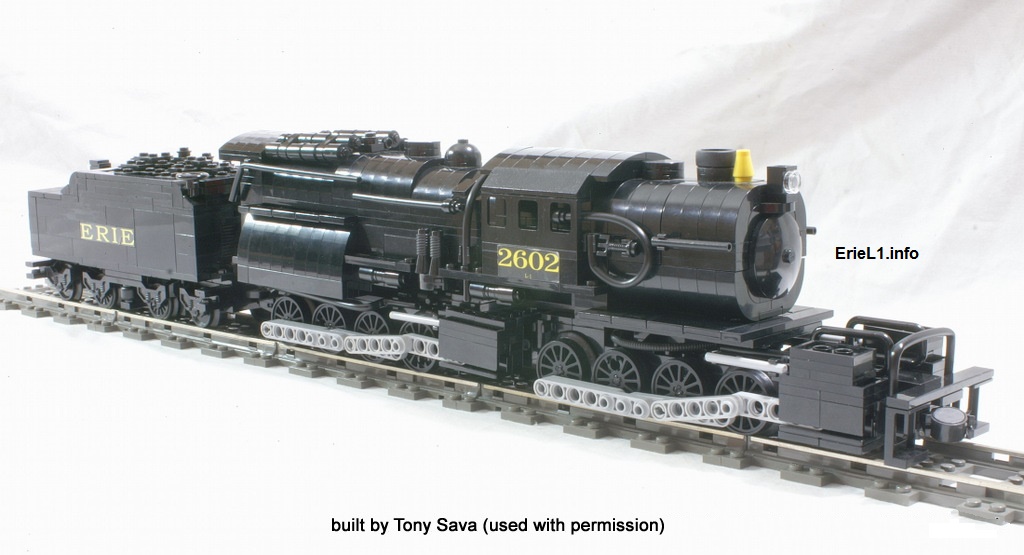 |
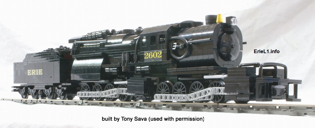 |
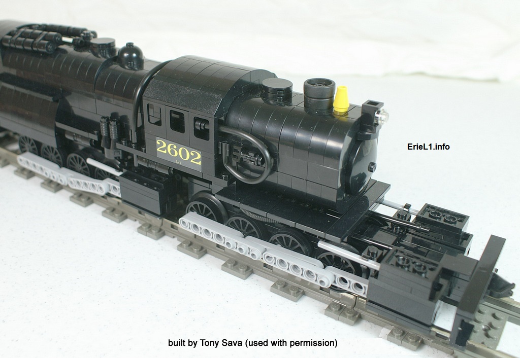 |
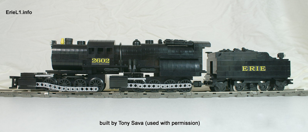 |
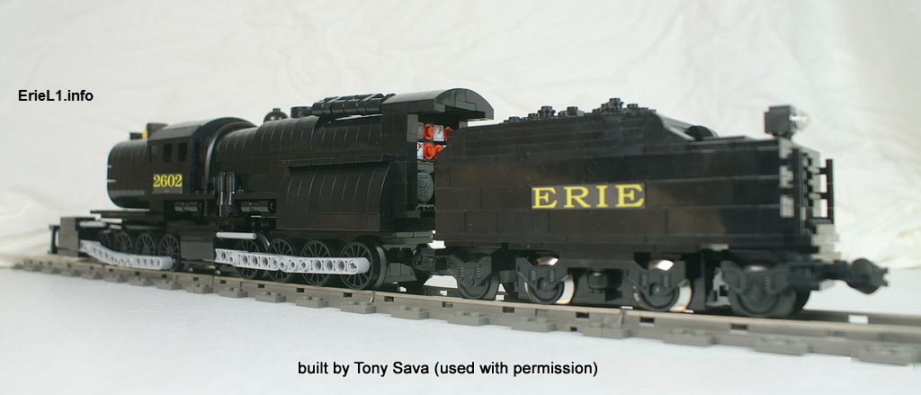 |
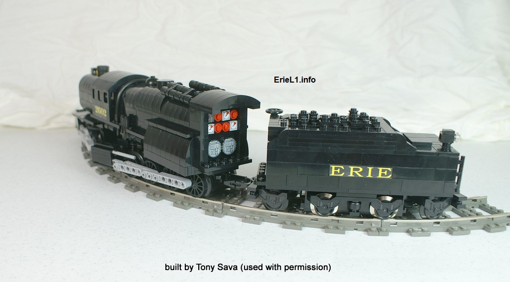 |
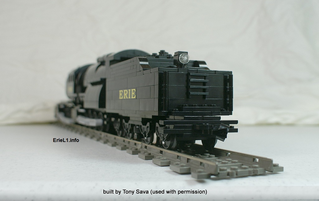 |
 |
It was inevitable. In March 2024, I made acquaintances with Adam Hofmann on Facebook, who was looking for erecting drawings for a Delaware & Hudson Camelback. I gave him a lead, and in conversation he mentioned he executed a kitbash of an Erie L1 in N scale, so I invited him to send a picture for inclusion here.
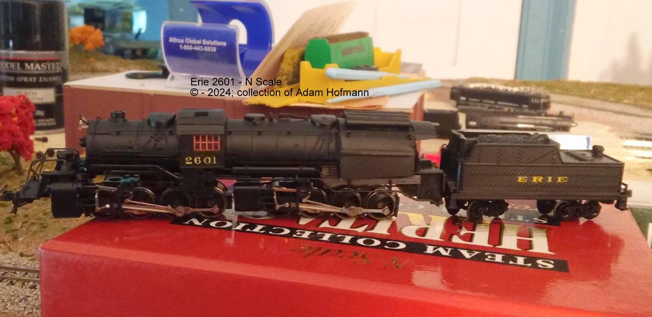
| Albrecht, Harry
P. "Camelback Locomotives" Steam Locomotives of Yesteryear Harry Albrecht Publishers - February 1971 |
Railroad
Gazette November 2, 1906 August 16, 1907 |
|
| Ames,
Gregory P. "Mother Hubbards' Bone of Contention" Railroad History #219 - Fall Winter 2018 Railway & Locomotive Historical Society; 2018 |
The Railway
Engineer February 1907 |
|
| Best, George M.;
Armstrong, G. W.; Edson, William D. All Time Erie Locomotive roster" Railroad History #131 - Autumn 1974, p. 22-113 (Railway & Locomotive Historical Society; 1974) |
The Locomotive September 14, 1907 |
|
| Bogen,
Jules, I. The Anthracite Railroads - a study in American Enterprise Ronald Press; 1927 |
Locomotive
Firemen and Enginemen Journal October 1907 |
|
| Charles R. Cullen
& Sidney D. Gridley Test of Mallet Articulated Compound Locomotive on Erie Railroad Cornell University (Senior Thesis); 1908 |
American
Engineering & Railroad Journal June 1908 |
|
| Harding, J. W. Firing of Locomotives, Hand Firing, Oil Burning, Type C-2 Boosters International Textbook Co.; 1912, 1920, 1935 |
Brother of Locomotive
Firemans & Enginemens Magazine Study Course: Combustion; July 1911 hard coal: p.21 |
|
| Hungerford, Edward Men of Erie Random House; 1946 |
Railway
& Locomotive Engineering XXXVIII #1 - January 1925 culm: p.79; Wootten: p.146 |
|
| Johnson, Ralph P., M
.E. The Steam Locomotive - Its Theory, Operation and Economics Simmons-Boardman; 1942, 1944, 1981 |
Steam Boiler
Engineering A Treatise on Steam Boilers and the Design and Operation of Boiler Plants February 16, 1929 |
|
| Le Massena, Robert A. Erie's Monstrous Mallets Railroad Magazine - June 1970; p. 30-34 (Popular Publications) |
Erie Railroad
(corporate documents as follows) Office of Division Engineer; Track Chart for Eastern District - Delaware Division; 1929 / updated 1933 Special Instructions, Delaware Division; July 1, 1914 Special Instructions, Delaware Division; November 1, 1921 |
|
| Mellin, Carl J. Articulated Compound Locomotives paper read before American Society of Mechanical Engineers American Locomotive Company - December 1908 (reprinted by Periscope Film; 2006) |
||
| Reed,
Brian Camels & Camelbacks; Loco Profile 9 Loco Profile Publications; Mears Caldwell Hacker - March 1971 |
SteamLocomotive.com in depth locomotive specifications |
|
| Sinclair, Angus Development of the Locomotive Engine Angus Sinclair Publishing; 1907 / reprint M.I.T. Press |
Wikipedia
for selected biographical information |
|
| Schopp, Bill Erie Camelback Articulated Railroad Model Craftsman Volume 23, No. 9, February 1955) (Carstens Publishing) |
Google
Maps for general cartography |
|
Swingle, Calvin F. Modern Locomotive Engineering Frederick J. Drake & Co Publishers; 1908 |
||
| Westing,
Frederick Erie Power Erie Mallets, p. 198-215 Alvin Staufer Publishing; 1970 |
||
| White,
John H. James Millholland and Early Railroad Engineering United States National Museum Bulletin 252; The Museum of History & Technology; Paper 69 (Smithsonian Press, Washington DC; 1967) |
Please
click here
to learn about the
AUTHOR.
|
x Even if what you have is not for sale, and
should it not already be included on this page,
|
|
|