


| RailWest Picture from the West Country Railway Archives |
Midford Signal Box
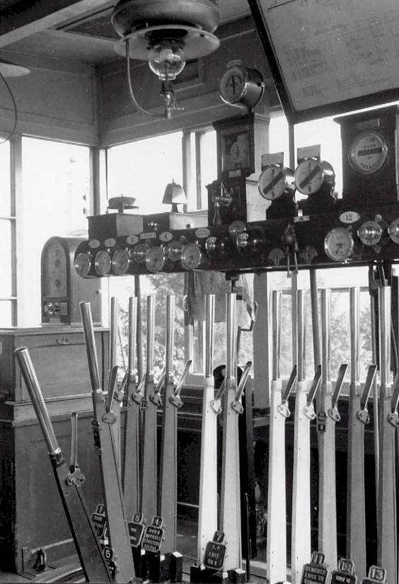
Photo by Ian Scrimgeour, courtesy of Signalling Record Society
This photograph, taken in May 1957, shows the interior of the signal-box at Midford on the former Somerset & Dorset Joint Railway. Midford station was situated at the northern end of the S&DJR main line, where the single-line from Bath became double-track to Wellow and then onwards to Evercreech Junction and Templecombe.
The signal-box contained a mechanical lever-frame with 16 levers, of which the first 13 are visible in the photograph. This frame was of the pattern of the signal contractors Stevens, with the levers positioned at 4.1/8" centres. Lever 5 was a 'push-pull' lever, so-called because it stood mid-way when normal and was either pushed or pulled to operate two separate signals. This was an economy method to reduce the number of levers and hence the cost of the frame. Each lever is fitted with a cast brass plate bearing the lever number and a description of its function, except for the spare levers 6, 9 and 10 (painted white).
To the left of the lever-frame, standing on top of a cupboard, is the Tyer's No 6 Electric Train Tablet instrument used for control of the single-line section to Bath Junction. Above the lever-frame was a shelf which carried the instruments for block working and other equipment. Working from left to right, the instruments seen on top of the shelf are as follows:-
Along the front of the shelf are a series of circular indicators for some of the signals at Midford - the needle in each indicator showed whether the respective signal arm was in the 'on' or 'off' position. There are also some circular plungers, which operated electric locks on some of the signal levers in conjunction with the track circuits and other controls. Most of the plungers were in brass cases, but in the middle of the shelf can be seen two bakelite examples. Out of sight to the right on the shelf were further indicators, as well as a Sykes plunger lock instrument. This was used in conjunction with the block working to Wellow for Up trains, because of the regular practice at Midford of shunting trains 'wrong road' onto the Up line.
Sometimes, when trains were shunted away rather than passing straight through the station, certain signals could not be cleared again for subsequent trains because they were locked by the Sykes equipment. In such cases the signalman had to use a special key to release the interlocking and two (brass) keyholes for this purpose can be seen to the right of the bakelite plungers (below the track-circuit indicators). The Sykes keys can be seen hung on the front of the shelf between the two keyholes - handy for that quick release!
Above the instrument shelf can be seen a part of the framed signal-box diagram. Click here to see a sketch (77KB) of the signal diagram for Midford during the 1950s period.
© Chris Osment 2002
|
© West Country Railway Archives 2002 Page last updated: 3 Feb 2011 |
Home Page: http://www.railwest.org.uk E-Mail: railwest@bigfoot.com |
||||||


