


| Home | History | Layout | Roster | Overhead Railway | Halloween Railway | Tech Tips | Links |
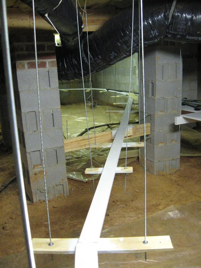
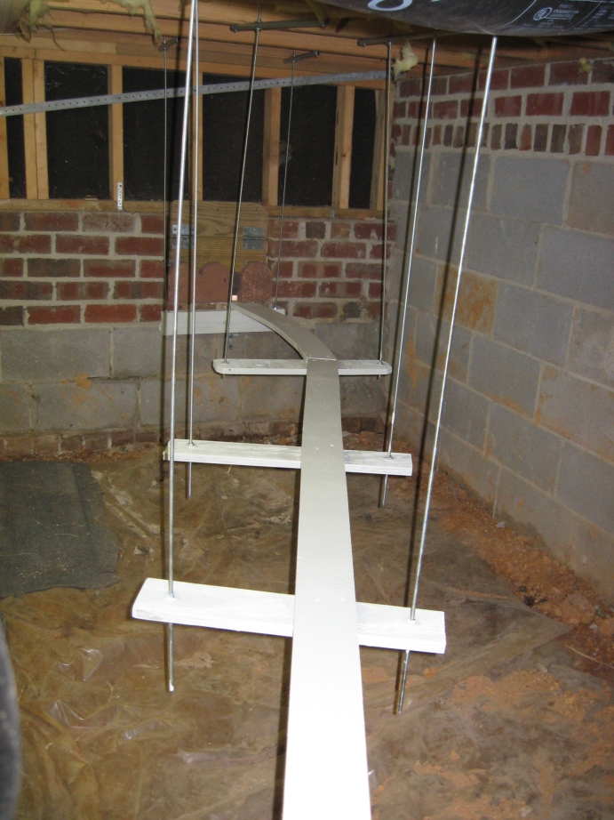
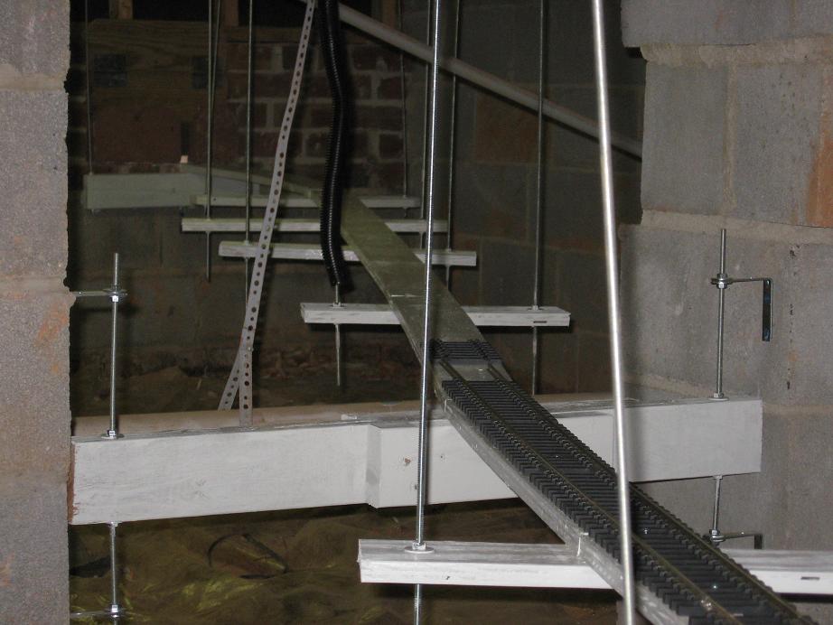
After constructing the railyard that I found that I needed to shift the location of the #6 switch so that It was a straight shot from the switch to the rail yard. As a result I had to add a couple of more supports to expand the roadbed to accomodate the shift.
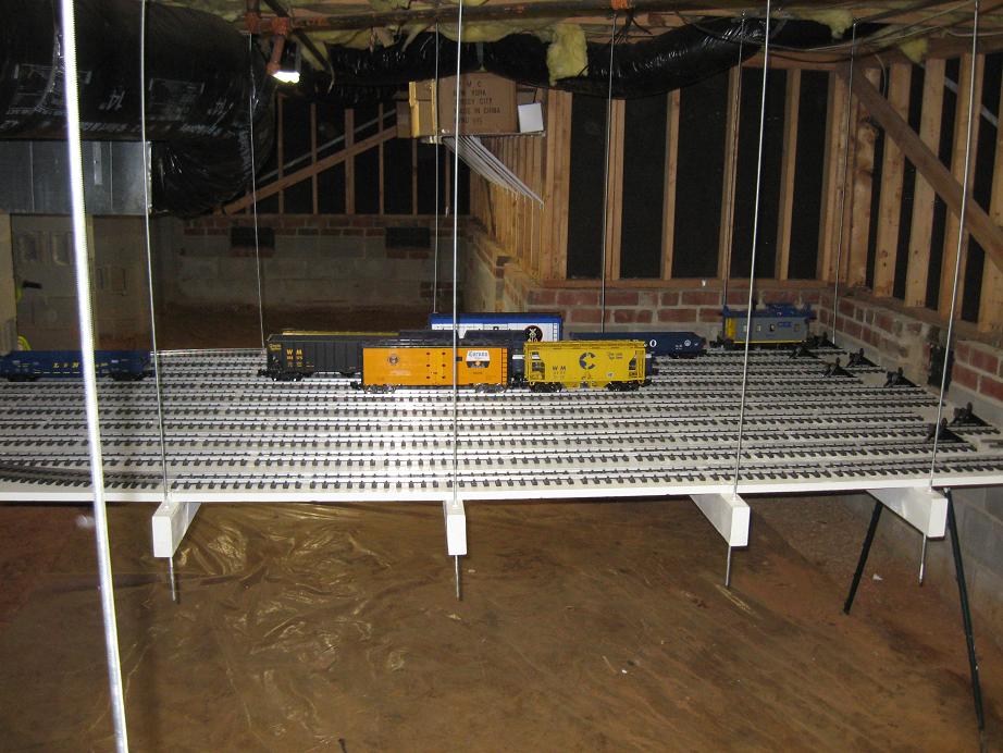
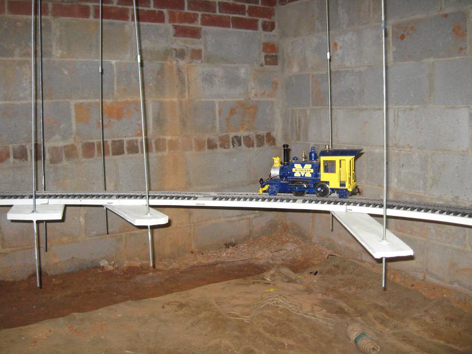
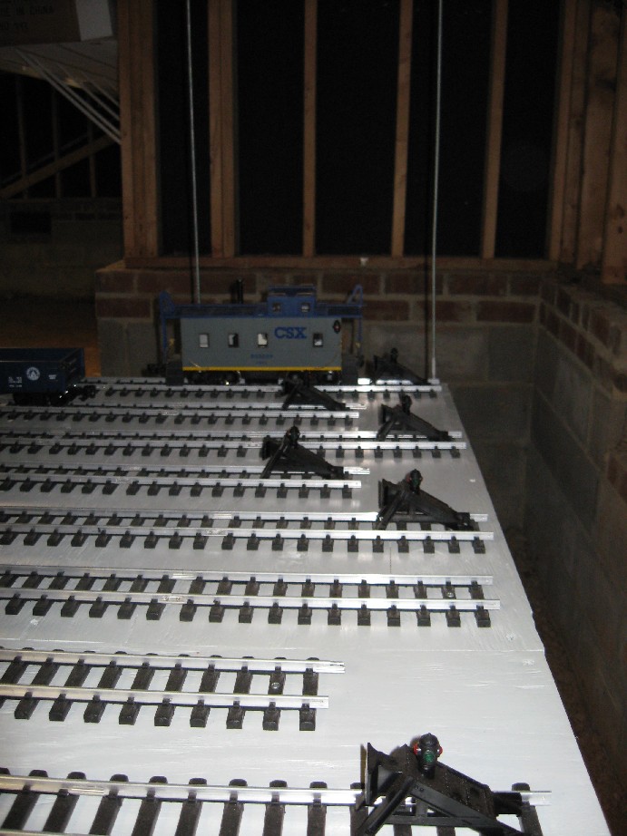
For the final roadbed cuts, I started at the #6 switch and worked my way towards the back of the house. I cut the roadbed as necessary at supports and screwed the roadbed to the supports with #8 x 1 1/4" wood screws. Then I started from the other side of the #6 switch and proceded to complete the roadbed to the side of the house. Once done with the roadboad I pained it with exterior paint. I got a gallon at Lowe's that was mistinted and on clearance for $5. Initially I just painted the roadbed and left the supports to be painted later.
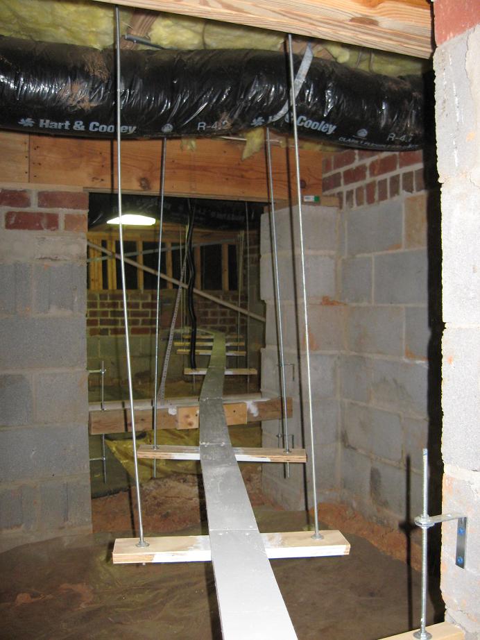
I've completed painting the roadbed and supports.
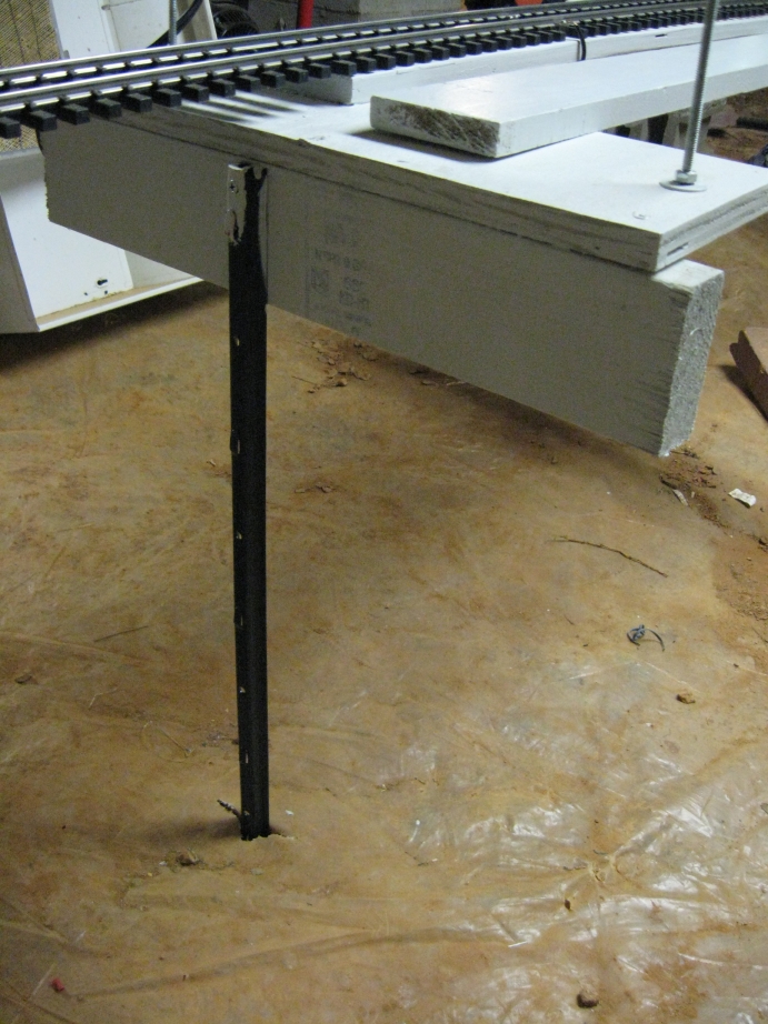
Most of the roadbed is pretty rigid now that it is attached to all of the supports and the railyard. One place there is a lot of motion is where the lift-up bridge will be that will allow me access around the crawlspace. To make this protion more stable I added a 'U' stake like the two I used on the end of the rail yard.
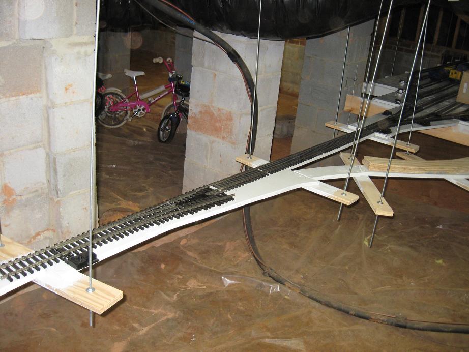
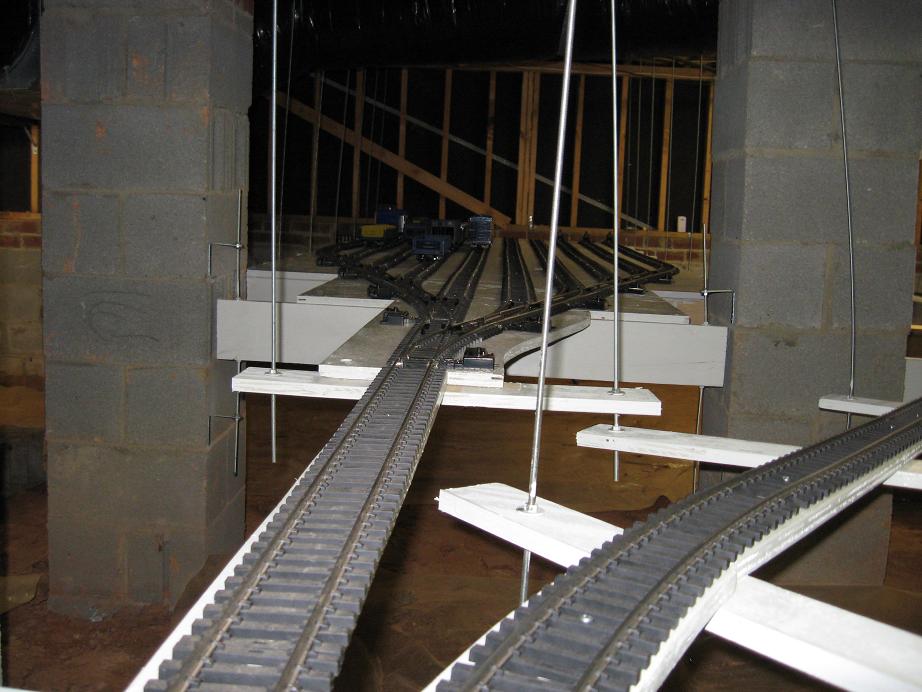
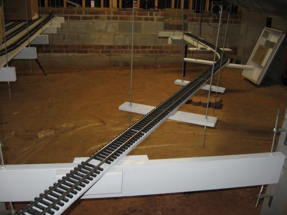
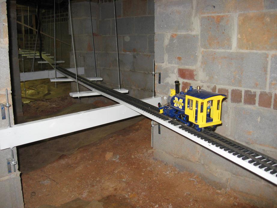
I finally have gotten to bend the rail for the railway. I removed the screws from the bottom of the rail that hold the ties to the rail. I then started at the #6 switch and started towards the back of the house. I used the "Stay Parallel" clamp from Train-Li to hold the ends of one end of the section of track so that they will match up with the divergent rails on the #6 switch. I then used the bender to bend the track to match the road bed. This rail bender is GREAT! It made the process very easy. I am allowing the rail joints to stagger as the rails bend so I will have to alter the ties as I continue around the track to allow the rail clamps space between the ties. For this first section I was able to just shift the ties on the rails, I did not have to cut the ties. For the curved portions of the track I used a SplitJaw double clamp to clamp the two pieces of track together so that the railbender could continuously bend from one section to the next. To complete the bending of the rail from the #6 switch to the back of the house took about an hour. It was an amazingly simple task.
I then continued from the other side of the switch towards the side of the house. For this secion since there was a longer curve, I needed to cut some of the ties to fit around the rail joiners. I am using 4 1/2' sections of track so I was able to take the 1/2' tie section and cut it to use in between the joints in the track. I was not able to complete the rail today But it will not take very long to complete the rail under the house.
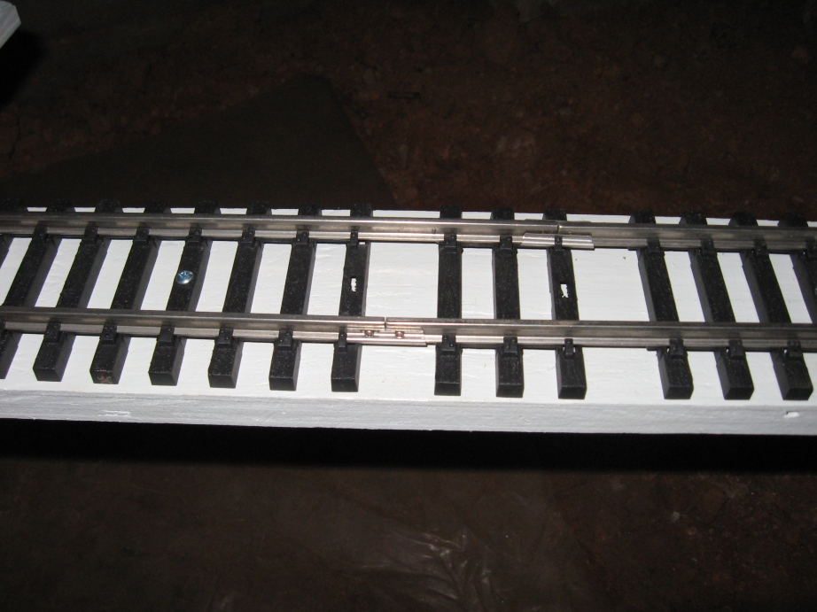
I also cut a piece of rail to fit between the #6 switch and the railyard. I used my Dremel tool with a cutting blade. It worked faily well but the disc was only able to cut two rails befor being worn down to nothing. I miscut only rail and had to cut of a 1/8" more. I had used by only cutting disc, so I used a sanding disc for this cut. It actually cut much better than the cutting disc. However, they are very brittle so I broke one and had to use a second to finish the cut.
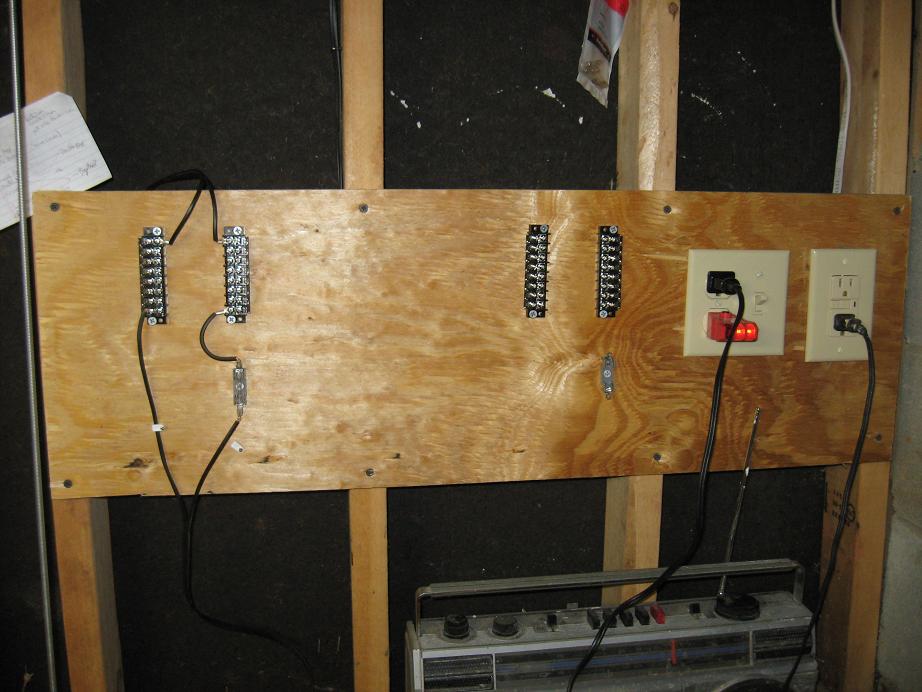
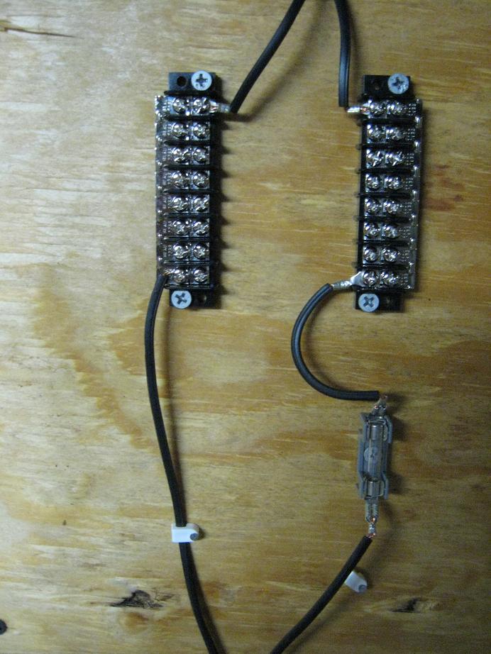
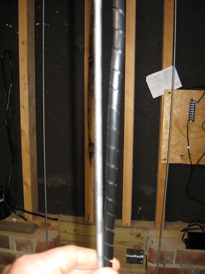
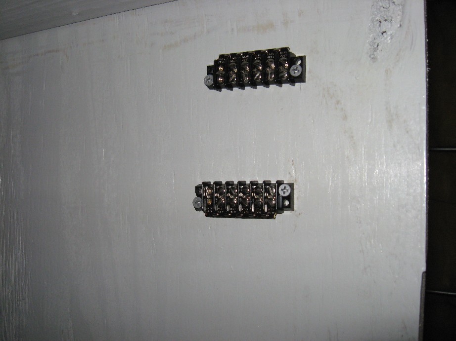
Even though I had not finished bending the rail. I decided to get some power to the track. I ran a dedicated circuit from the breaker box to an GFCI outlet on the back wall of the house. I then continued the circuit to a switch and outlet controlled by the switch. Eventually I will run wire up into the house and have 3-way switches (one in the crawlspace and one in the house) to control the outlet in the crawlspace and also an outlet in the house. My plan is to keep the power supply plugged in up in the house an run the DC to the crawlspace. I then mounted some 8-position barrier strips to the wall with an 8 position jumper on each to act as distribution points for the DC power. I made two so that I can have one dedicated to constant DC power and one connected to my Train Engineer to control the trains. I also mounted a fuse holder inline with each block. I then ran 16 gauge wire from one block up the wall, across the floor joists, and down along one of the threaded rods to the roadbed. To protect the wire I used spiral cable wrap around the wire and zip tied it to the rod.
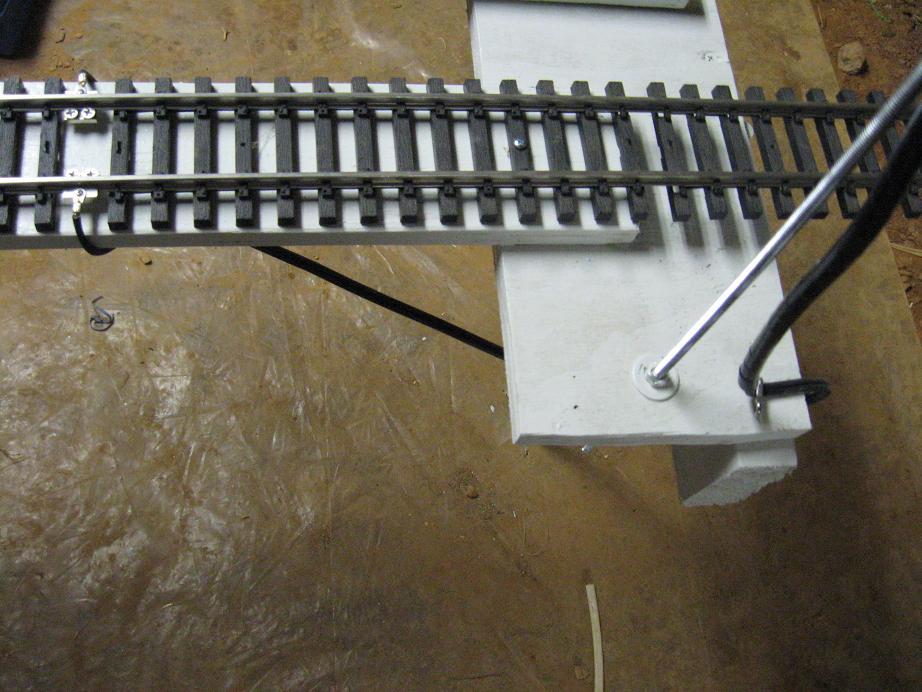
On each end of the wire I soldered a ring terminal to connect to the barrier strip and spade connecters to connect to the fuse mount. At the rail end I soldered ring connectors and connected the wire to Aristocraft rail clamps.
I was finally ready to try a test. I popped a 2 amp fuse into the fuse mount for a first test. Connected a power supply and turned up the power. The lighted bumpers on the railyard lit up beautifully. Next I brought down my Rogers 2-4-2 and put on the track. It worked like a charm. I will put a larger (8 amp) fuse in for the variable DC block and a 1.5 amp fuse in for the constant DC block eventually.
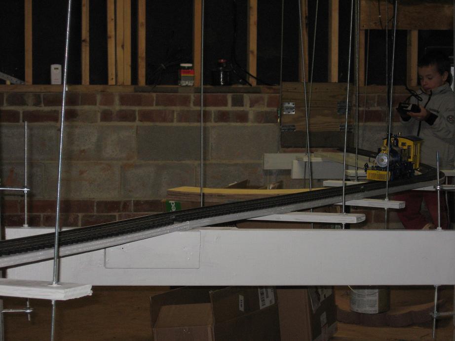

Here's a video of the first test run.
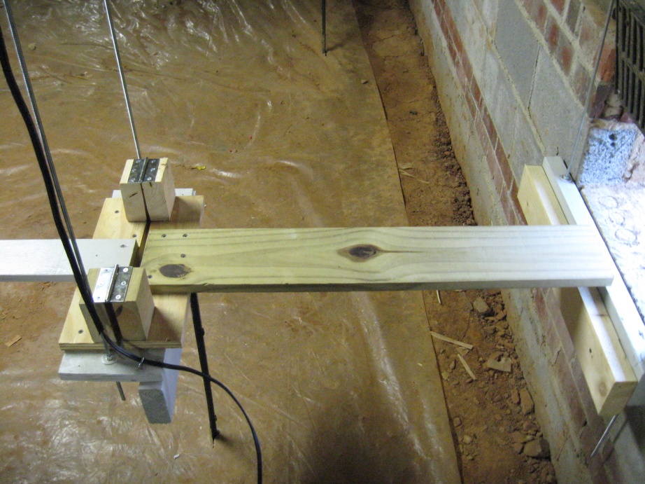
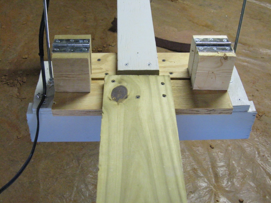
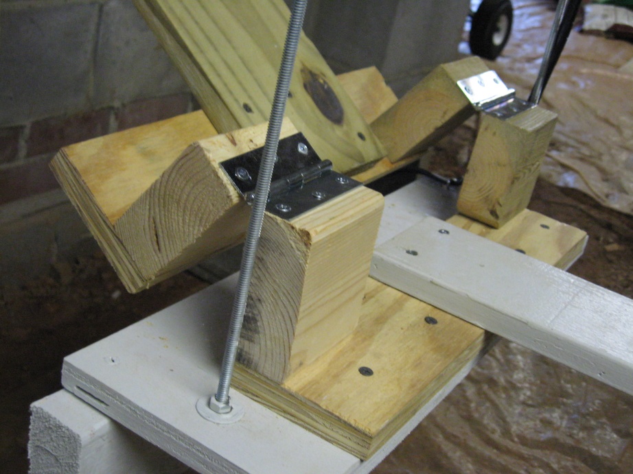
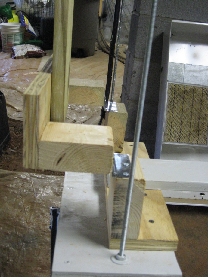
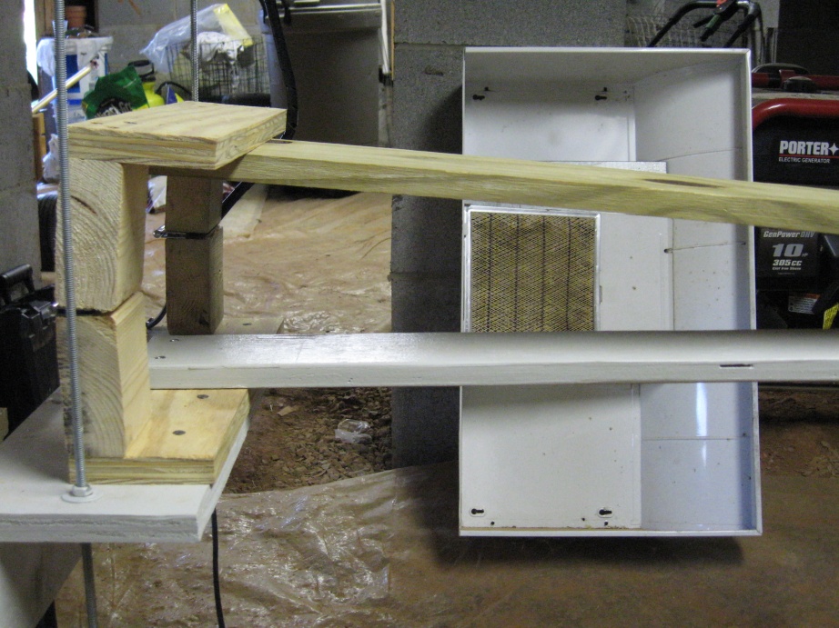
I've completed bending the rail for under the house except for the lift up bridge I'm going to leave that until I get the rail down outside the house. Instead of spending the money on the Hillman's bridge kit, I decided to give it a try on my own. Using their bracket as a guide I fashioned the bridge out of 3/4" plywood and 2x4 pieces. The key to the design is to have the hinge above the rail so that the rail on the bridge will swing away from the abutting rail when you lift the bridge up.
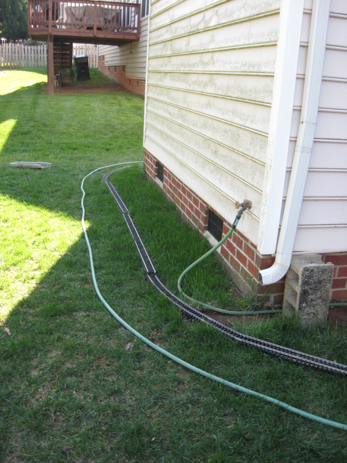
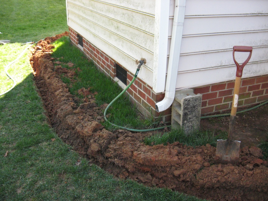
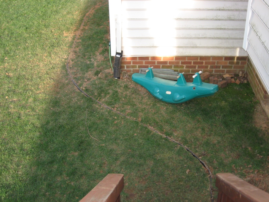
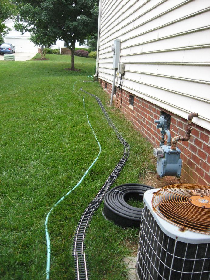
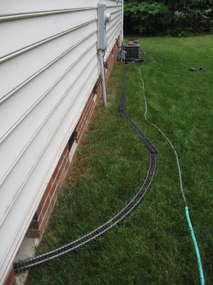
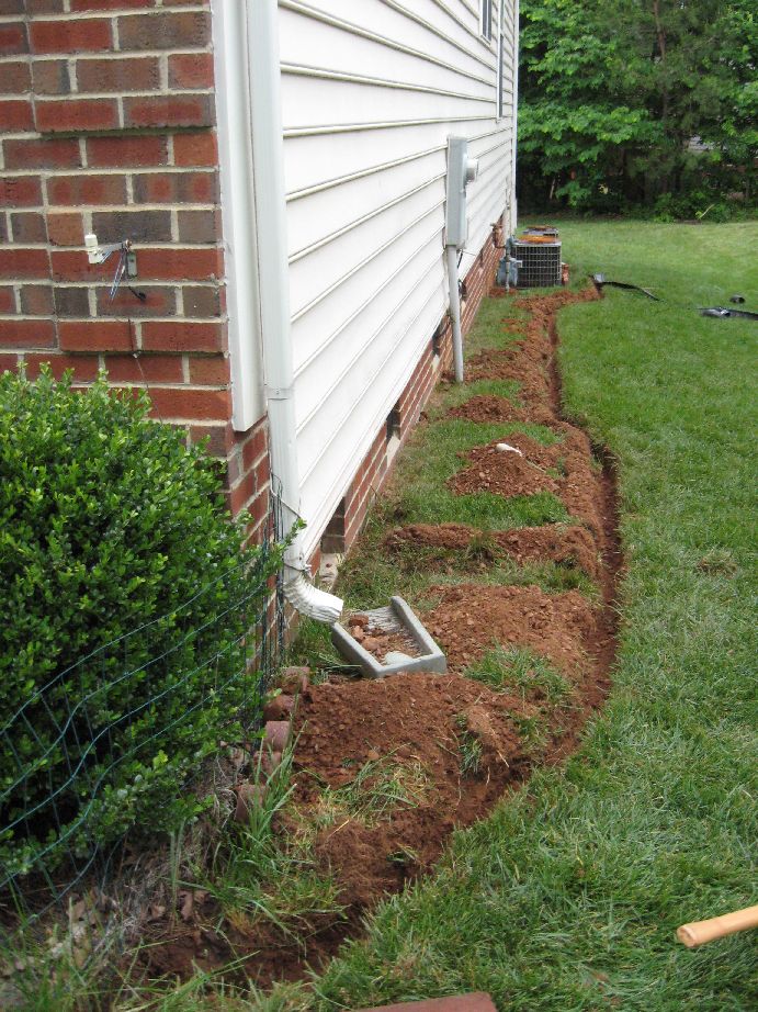
With the completion of the bridge the trackwork is pretty much complete in the crawlspace. So the next step was to head outside and get started at the back of the house. I started by putting down the track roughly where it was going to be laid. I then used a garden house to mark where I am going install plastic edging.
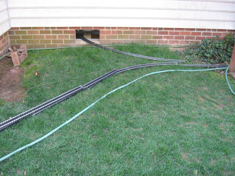
Next I took a spade and cut into the sod and laid the sod back along the length of the hose.
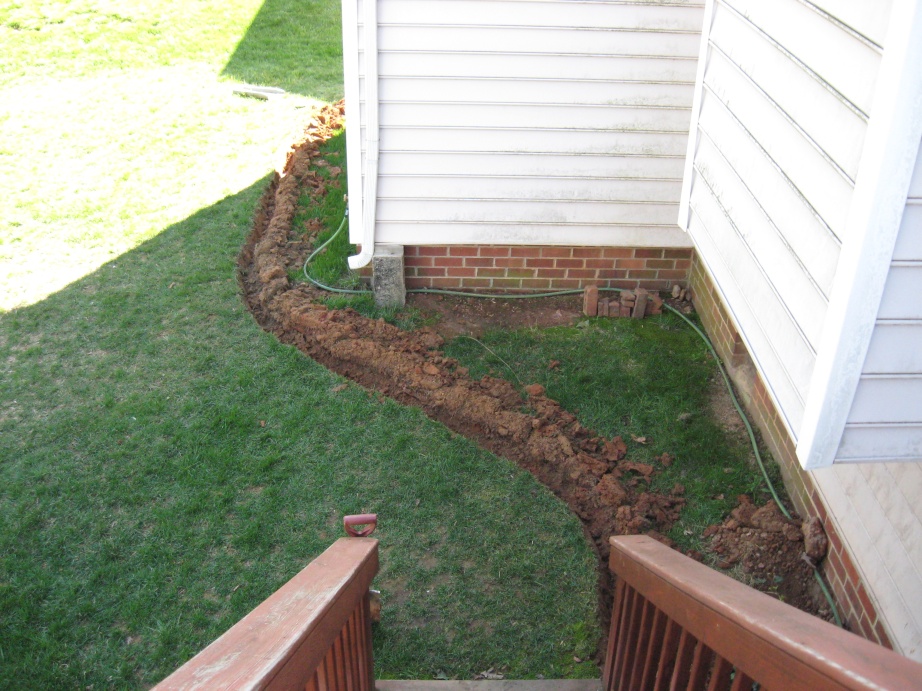
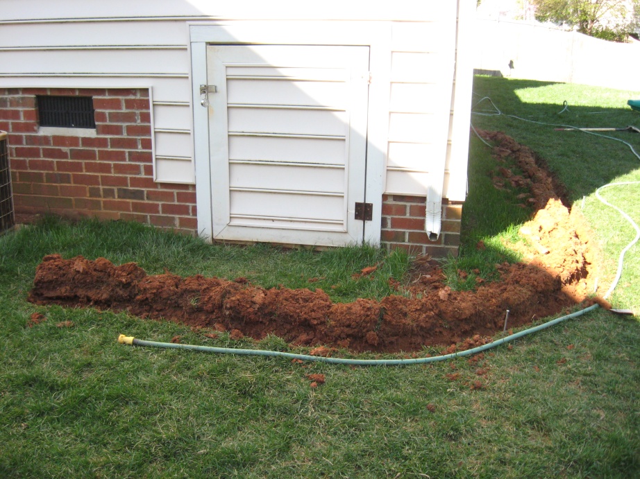
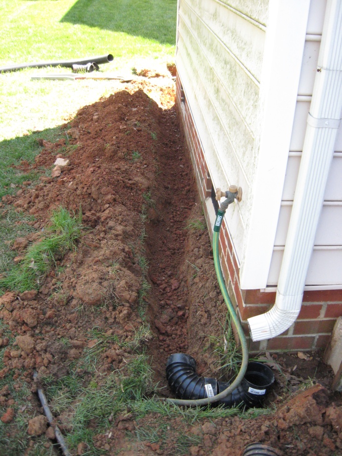
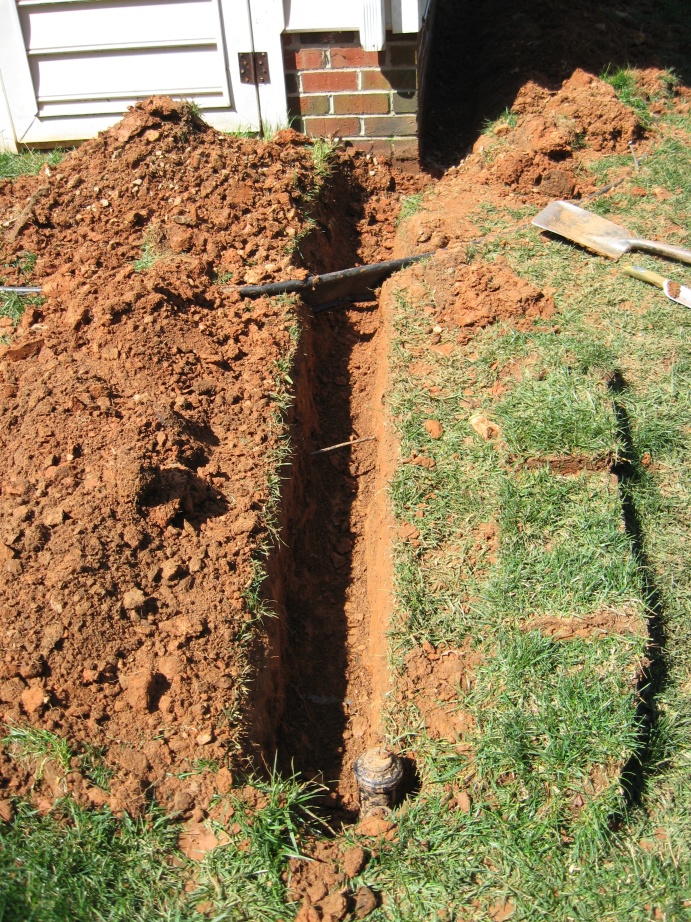
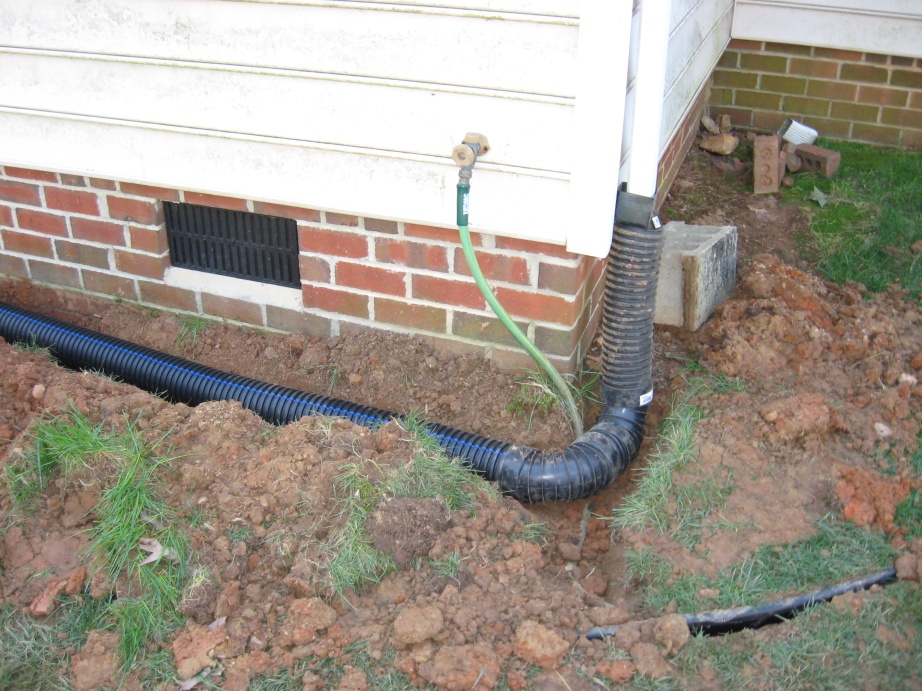
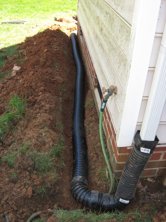
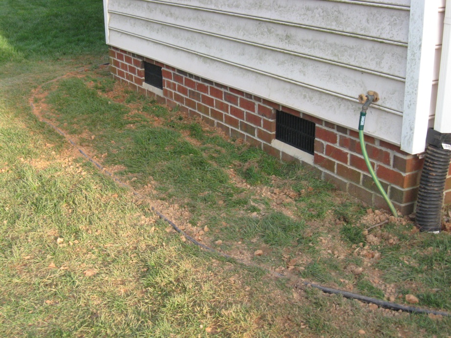
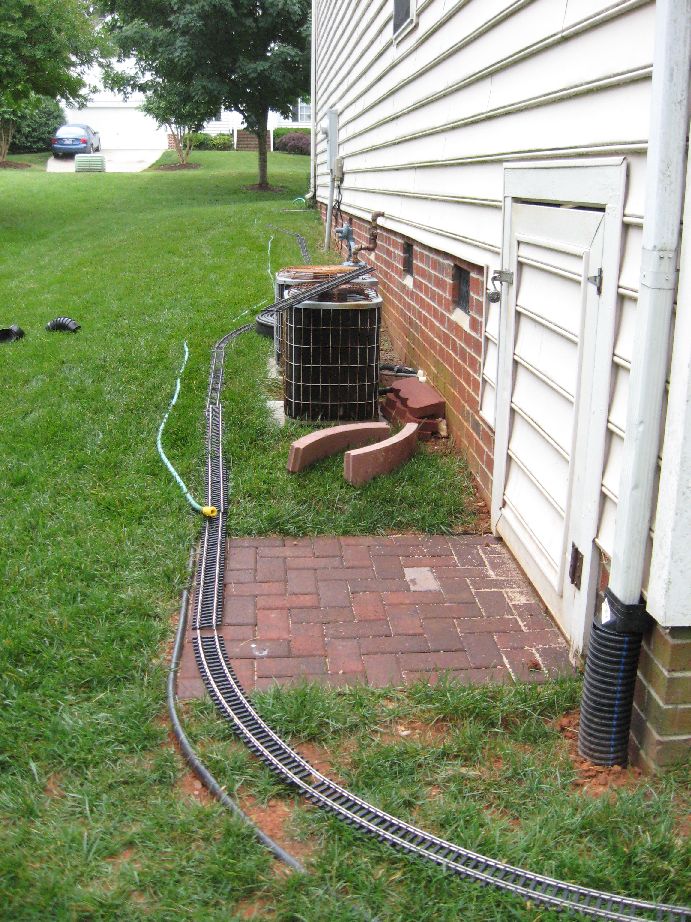
I spiked the end of the edging by the bottom of the deck stairs and laid the edging into the trench and folded the sod back against the edging. This holds the edging in place and will let the ground settle back around the edging. I can go back later and remove the sod between the house and the edging. Until then I can mow over the edging without any problems. Next I wanted to route the downspouts so that the water from them wouldn't have to run on top of the ground and interfere with the track work. To accomplish this I used 4" corrugated drain tube. I trenched along the house, connecting the two down spouts to the drain tube. I then ran the tube under the edging I just installed and out into the yard. I then put an elbow on the drain tube to bring it up the the surface and put a green drain cover over the end.
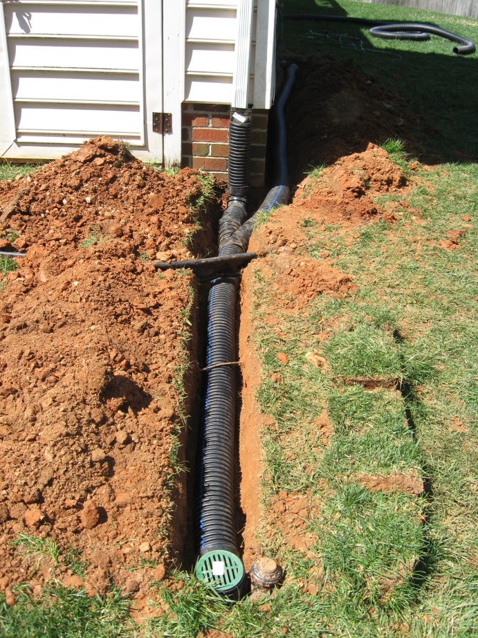
I then filled in the trench over the drain tube and replaced the sod over the tube.
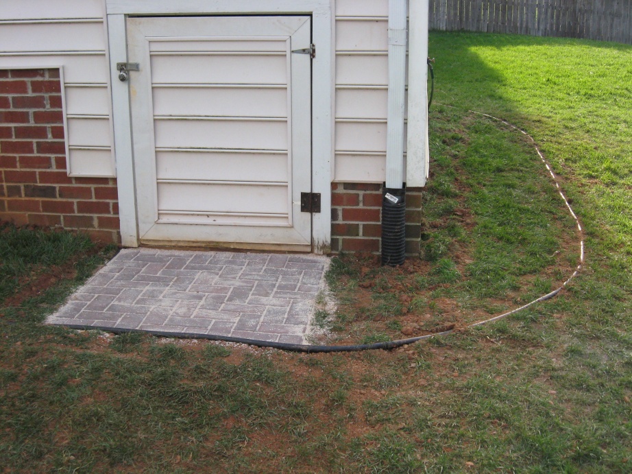
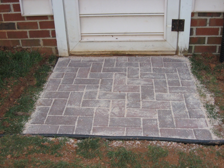
I then constructed a paver pad by the crawlspace door. I've been having some drainage problems around the door so I lowered the ground level. I also needed to provide a solid base since I bring the mower and various other things from the crawlspace and will be walking and rolling things over the track here.
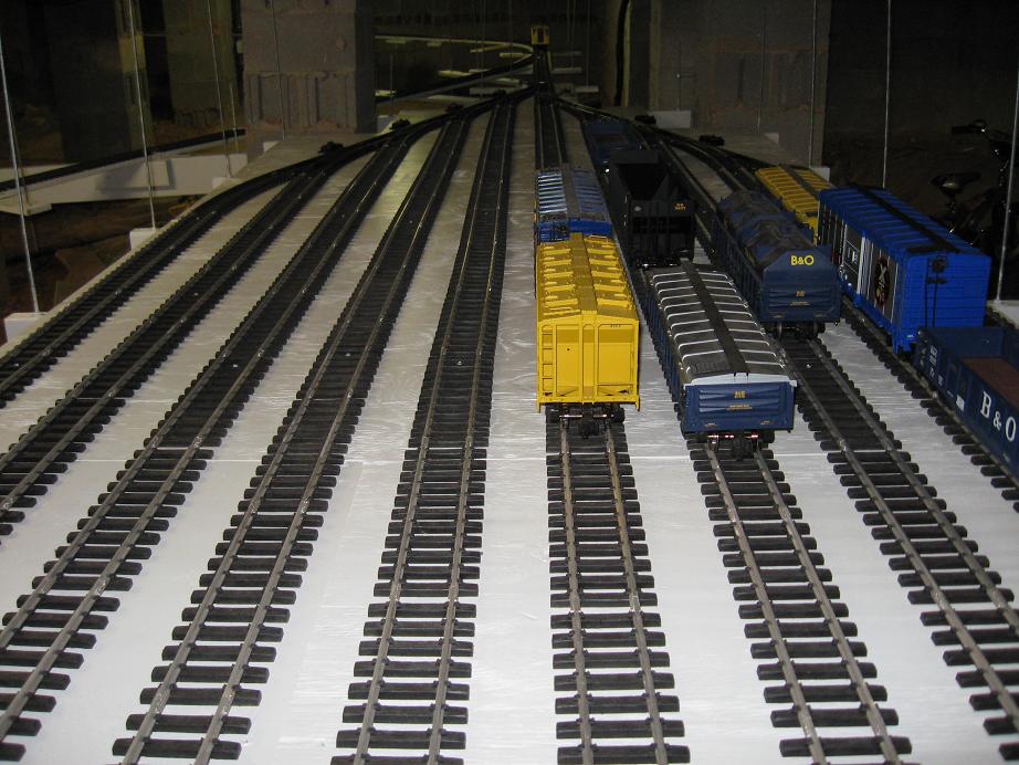
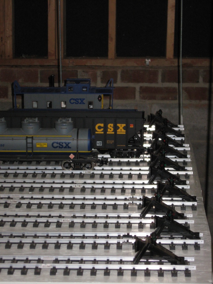
I finished up the track in the rail yard. Half of the tracks in the rail yard were about 6" shorter than the other tracks. This was due to the switches being longer than the 1' sections of track used for the yard. I cut two 1' sections in half to make up the difference. When installing these sections, I used plastic joiners to separate them from the rest of the yard track. This is so I can power the lighted bumpers on the ends of the track separately from the train control and have them lit constantly. I will go back and install the plastic joiners before the last sections of track on the rest of the railyard.
I have an old 12V 1.5 amp power supply I will use for the contant DC power. I also installed a couple of 6 position barrier strips under the railyard to distribute the constanct DC power. This will also serve as a power distribution point for the switch motors for the railyard switches.
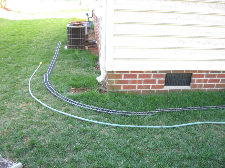
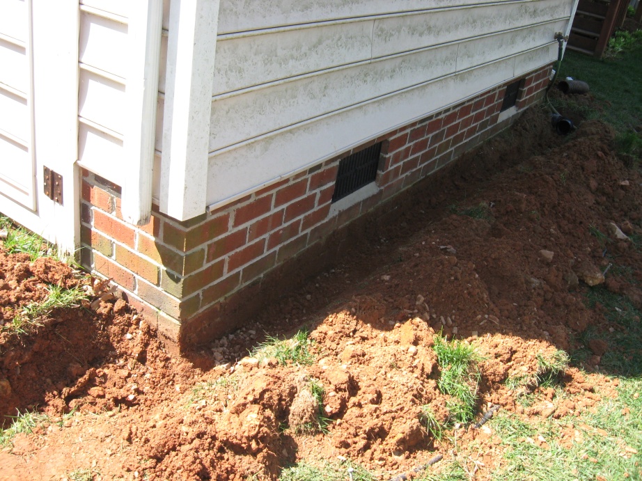
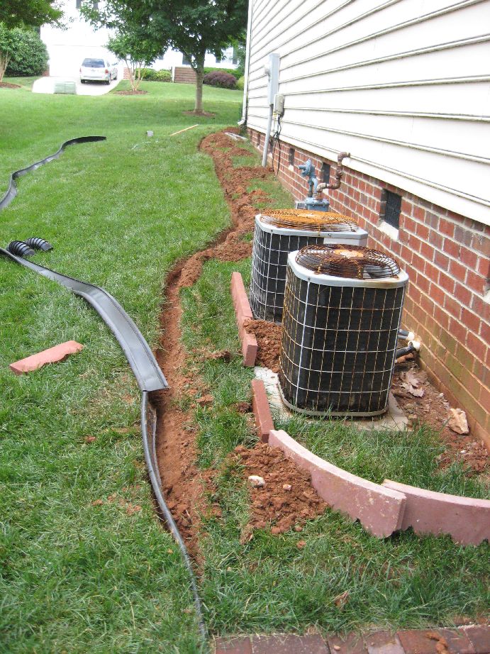
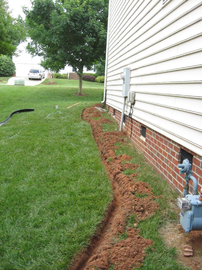
I continued roughing out the layout along the side of the house. Again I put down the track roughly where it was going to be laid. I then used a garden house to mark where I was going install plastic edging.
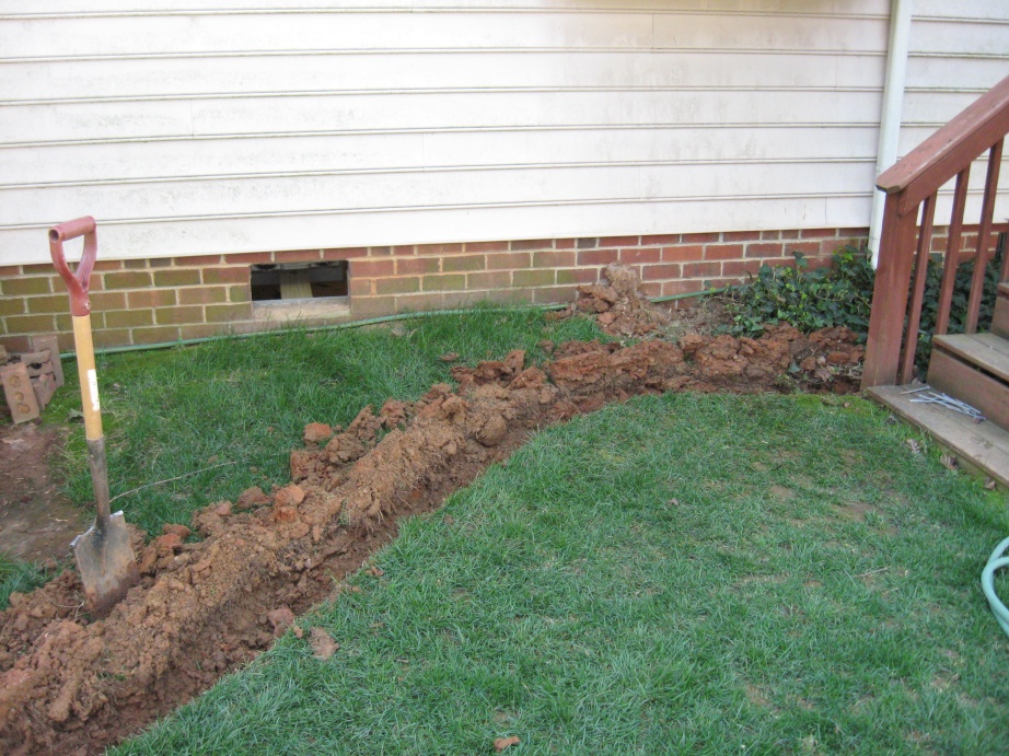
Again I took a spade and cut into the sod and laid the sod back along the length of the hose. Once I dug the trench I placed the eding in the trench and backfilled with the sod. I also installed another drain tube for the downspout and the front of the house that goes under the eding out into the yard.
So what has construction cost me this year? Here's what I've used and how much
it cost.
| Item | Cost |
|---|---|
| 8 x 1-1/4" wood screws (100ct.) | 4.81 |
| 6 x 3/4" pan head screws (100ct.) | 3.97 |
| 10 x 2 pan head scres (50 ct.) | 4.81 |
| threaded rod | 4 @ 2.97 |
| 1 Gallon paint | 5.00 |
| 5' "U" post | 3.28 |
| 15 Amp receptical | 1.87 |
| single gange wall box | 2.80 |
| single outlet box cover | 0.61 |
| double gang wall box | 2.16 |
| double box outlet cover | 1.55 |
| 3-way switch | 1.57 |
| 15 Amp GFCI outlet | 13.59 |
| 8-poisition terminal strip | 4 @ 2.49 |
| 8-position jumper | 6 @ 1.99 |
| Fuse holders (2 ct.) | 1.99 |
| cable wrap | 4.99 |
| 8 amp fast blow fuses (4 ct.) | 1.99 |
| 1.5 amp fast blow fuses (4 ct.) | 1.99 |
| 16 Gauge wire (100 ft.) | 28.99 |
| cable wrap | 4.99 |
| Sub Total | 118.76 |
| Sales Tax | 8.02 |
| Total | 126.78 |
This page last updated May 26, 2009


