


SP Maintenance Manual
Page 10
|
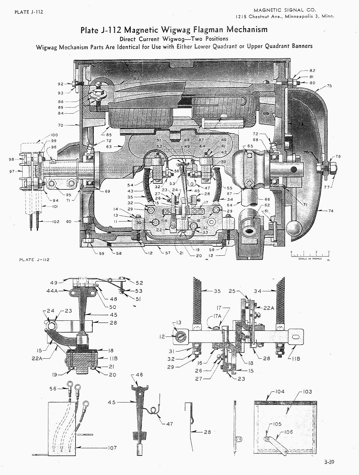
Replacement coils are 1.3 ohms each and consist of 400 turns of No. 15 enameled magnet wire. Coils may be either shop made or purchased. On mechanisms not already equipped with coil supports (Ref. 87, Plate J112) one of these is to be installed on each side of each coil in the center of the pole piece Coils are to be firmly wedged in place with maple wedge (Ref. 86). Magnet coils are to be so connected that the same relative magnetic polarity is obtained on each side. This may be tested by use of a compass. When the coils are energized the pole pieces near-est the banner end of the mechanism shall attract the same end of the compass needle and the pole pieces nearest the gong end shall attract the op-posite end of the needle. 9. Ball Bearings.
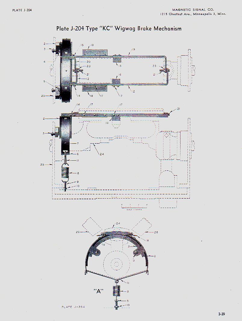
Bearings that are to be re-used must be carefully cleaned and freed from all traces of hardened grease. If cleaned bearing does not spin freely with out roughness do not re-use. Bearings are to be packed with light Marfax Grease to protect them while mechanism is in storage. This will be supplemented by period-ical lubrication with Pale Semaphore Oil in the field. 10. Brake Drum -(See Plate J204, Bulletin
No. 54.)
|
Page:
-| 1 | 2
| 3 | 4
| 5 | 6
| 7 | 8
| 9 | 10 | 11
| 12 | 13
| 14 |-


