


SP Maintenance Manual
Page 9
|
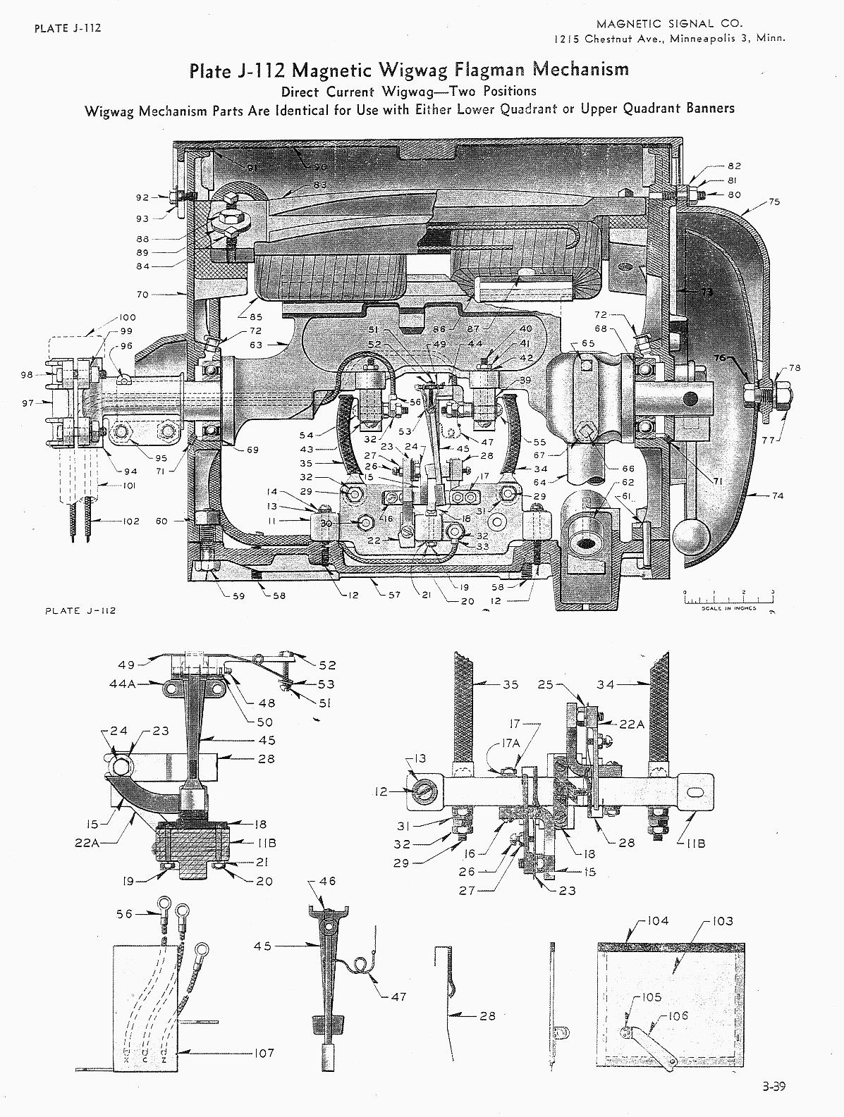
1. Porcelain terminal boards are to be replaced with Bakelite terminal boards. (Ref. ll, Plate J112) 2. Porcelain bracket supports are to be replaced with Bakelite bracket support (Ref. 39, Plate J112). 3.
4. When ordering new condensers to replace contact condenser (Ref. 107, Plate J112) specify 0. 3. Pyranol Capacitors No. 23F38lGl0I, 2000 Volts DC Capy. 1.0 N.F.D. Two of these will be required to replace the one double unit (Ref. 107). The new capacitors are to be located near the banner end of the base casting on the terminal side or the terminal board in such position that they do not interfere with brake adjustments or with terminals. They are to be attached by 3/8" X 10-32 round head brass screws and lock washers tapped into the base casting. 5. Mechanism is to be wired for independent lamp control as shown on wiring diagram JH521, Plate 10 Bulletin No. 54 unless other special arrange-ments are so specified. 6. No welding is to be done on wigwag parts other than top cover casting (Ref. 90, Plate J112) or bell cover casting (Ref. 75). 7. Mechanism is to be completely dismantled and all parts thoroughly cleaned. All cast iron parts are to be painted with aluminum paint, care being taken to keep paint off pole surfaces of armature and magnets. These are to be treated with Union Pole Face Treatment or a good grade of clear lacquer when other adjustments are completed. Also keep paint from all other assembly surfaces. |
Page:
-| 1 | 2
| 3 | 4
| 5 | 6
| 7 | 8
| 9 | 10 | 11
| 12 | 13
| 14 |-


