


SP Maintenance Manual
Page 4
|
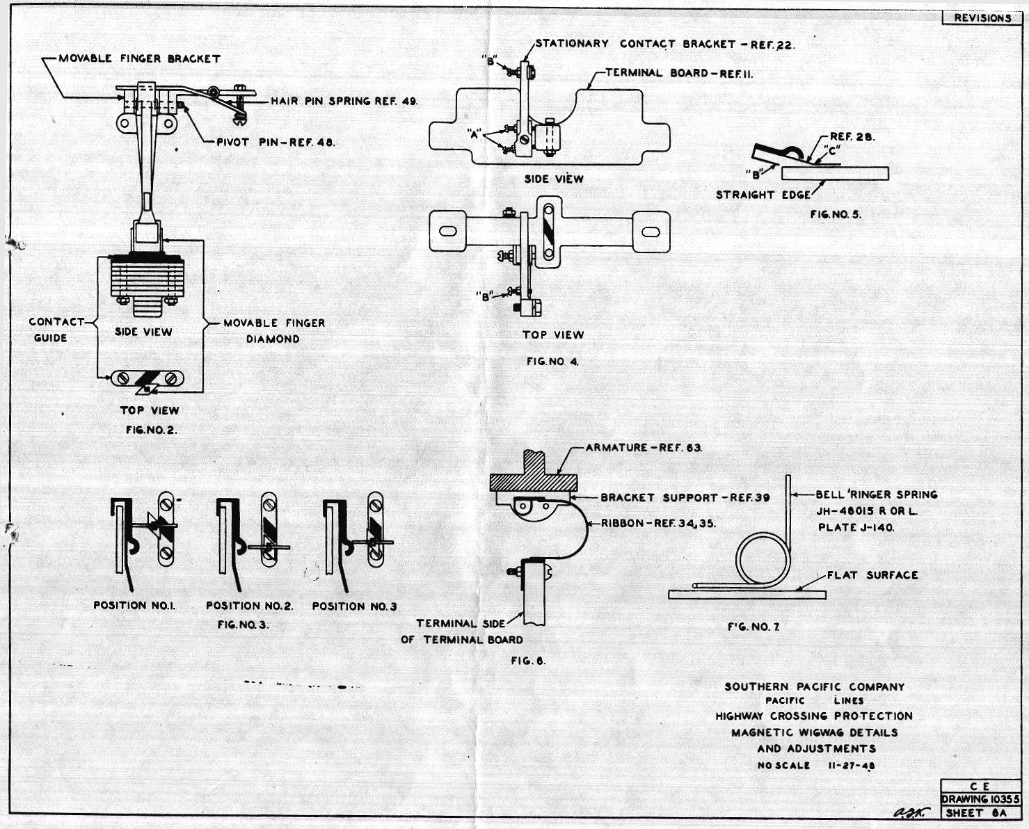
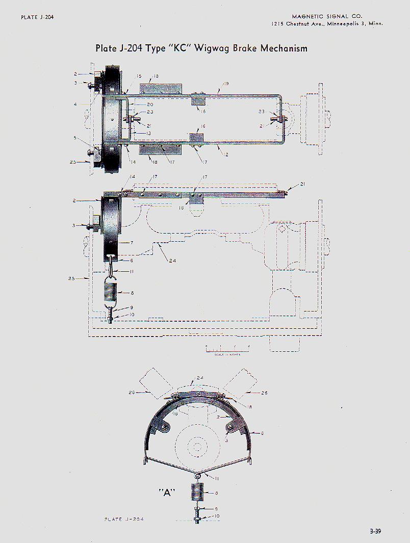
The screw shown as "B in Fig. 4 is to be set so that it just touches the contact without pressure when the contacts are not engaged. 6. Brake Adjustment. Brake mechanism is to be assembled as shown on plate J204. The extensions of the brake arms (Ref. 19) which engage with lugs on the brake band are to clear the top of the band 1/32" when the brake arms are in the released position and are to clear the top of the lugs a minimum of 1/32" when the arms are picked up. Brake arms and angle piece (Ref. 18) are to clear pole pieces a minimum or 1/8" when in the picked up position and armature is in any part of its operating stroke. When installing new brake arms it will probably be necessary to bend the angle piece (Ref. 18) to obtain proper clearance. To avoid distortion of other parts, do not attempt to bend the angle piece while assembled to mechanism. Remove brake arm and hold in vice. Increasing the clearance of the angle piece will increase the brake pick up voltage so avoid over bending. The maximum pick up is 3.0 volts measured across the coils when the voltage is gradually increased with a variable resistance in series with the bell con-trol. The operating stroke of the brake arm is adjust-able within certain limits by bending the brake arm support (Ref. 16). When this adjustment is complete the brake arm support must be parallel to the top of the slot in the armature when the brake is picked up. It is frequently found that sufficient adjustment cannot be made by bending the brake arm support. |
Page:
-| 1 | 2
| 3 | 4 | 5
| 6 | 7
| 8 | 9
| 10 | 11
| 12 | 13
| 14 |-


