


SP Maintenance Manual
Page 3
|
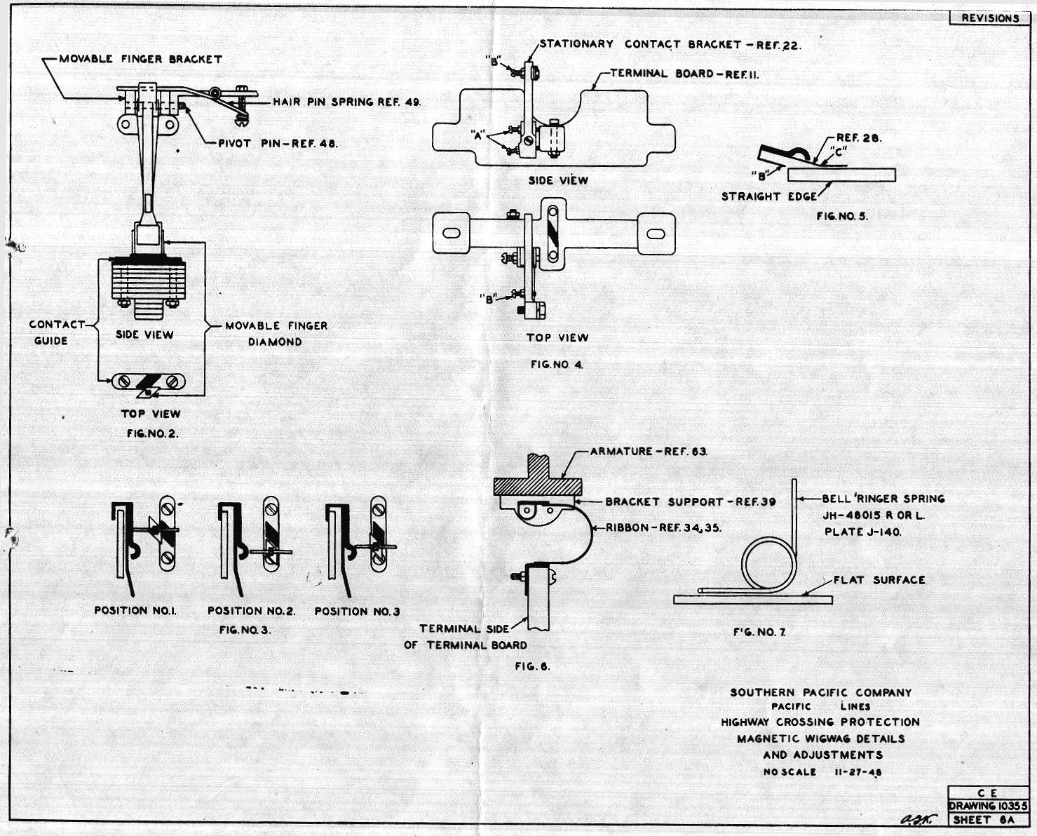
New Stationary Contacts (Ref. 28) are usually properly bent to provide proper contact pressure when received and require no alteration; however, each contact should be checked as shown in Fig. 5 before it is installed. With the slotted end of the contact held against a flat surface the point B of the contact should be in the same plane. Should any bending be necessary to ob-tain this adjustment it must be confined to point C. The end "B" is to be parallel to the contact. No other bending of this part is permitted. The top member of the Stationary Contact Bracket is to extend across the top of the terminal board at "right angle and no bending of this part is permitted other than to correct already faulty adjustment. When the stationary contact is assembled on its bracket, the screws shown as "A" in Fig. 4 are to be adjusted so that; when the mechanism is in its normally in operating position and the contacts are engaged, the top member of the contact bracket is located as shown in Fig. 3 Position #1 midway between the contact finger and its backstop and slightly closer to the contact side of the finger. When properly adjusted it will be found that when the mechanism is held In a position in which the movable diamond is engaged with neither the sta-tionary diamond or the movable finger stop there will be a clearance of 1/32" to 1/16" between the contact surface of the movable finger and the hump on the stationary contact as shown in Fig. 3 Posi-tion #2. The Stationary Contact is adjustable laterally by means of the slotted end where it is attached to the bracket and it is to be so adjusted that in its downward stroke the contact surface of the movable finger engages about 1/8" past the center of the hump on the stationary contact as shown in Fig. 3 Position #3. The adjusting screws shown as A in Fig. 4 may be used to take up the wear on the contact surfaces of the movable finger and are to be readjusted as this wear progresses. |
Page:
-| 1 | 2
| 3 | 4 | 5
| 6 | 7
| 8 | 9
| 10 | 11
| 12 | 13
| 14 |-


