


| Barnstaple Town also Barnstaple Quay and Pottington |
|||||||||
|
|||||||||
|
|||||||||
Note: This page deals specifically with Barnstaple Town station and signal-box on the former London & South Western Railway line to Ilfracombe, also Barnstaple Quay station and signal-box and the signal-box at Pottington. Please click here for a separate RailWest page about the Lynton & Barnstaple Railway at Barnstaple Town station.
 |
 |
|
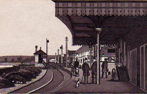
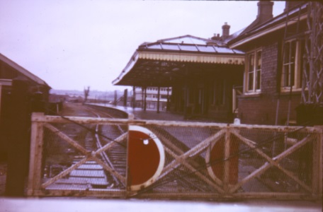
| An early postcard view of Barnstaple Quay station | Barnstaple Town station after closure circa-1973 |
The railway from Barnstaple Junction to Ilfracombe was opened on 20-July-1874 by the independent Barnstaple & Ilfracombe Railway Company, but it was taken over later in the same year by the London & South Western Railway (L&SWR). It had been inspected for the Board of Trade (BoT) by Lt Col Hutchinson on 15-July-1874, and was re-inspected by him on 30-September-1874 after the Company had completed some work requested in his original Report. Initially the line was single-track, with some of it constructed to 'Light Railway' standards, but by the end of 1887 the line had been upgraded to 'normal' railway standards throughout. By July 1891 the entire line had been doubled with the exception of the first mile from Barnstaple Junction to Pottington, which always remained as single-track.
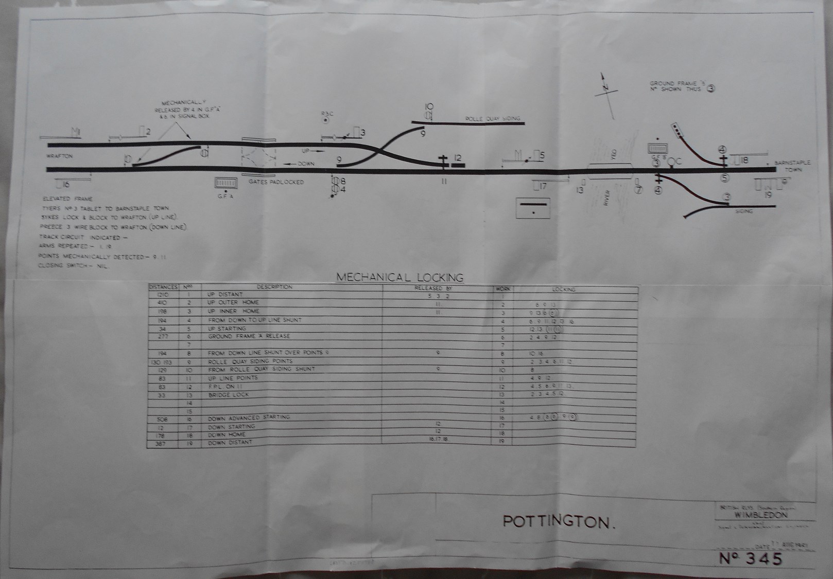
The single-track line left Barnstaple Junction at the west end of that station, passed under Sticklepath Road and then curved around to cross the River Taw on a long, curved steel bridge. Immediately on reaching the north bank of the river there was initially a Barnstaple Quay station, which consisted of a single platform on the Up (north) side of the line. Immediately to the west of that platform was a level-crossing (known later as Commercial Road crossing) which provided access from that road to the quay on the river-bank. This crossing was controlled originally by Barnstaple Quay signal-box, an elevated L&SWR Type 1 box (believed to have contained a 9-lever frame) which was situated on the Down side of the line immediately east of the crossing. A short distance further west there was another level-crossing (known later as Barnstaple Town crossing) giving access to the quay and this was also controlled originally by Barnstaple Quay signal-box. A short distance further west again the railway crossed a swing-bridge over the River Yeo (close to where it flowed into the River Taw), beyond which was the commencement of the double-track to Ilfracombe. This location was controlled by Pottington signal-box, an elevated L&SWR Type 3B box opened on 4-August-1890 containing a 19-lever Stevens frame; this signal-box was located on the Down side of the line immediately west of the swing-bridge and close to the single-to-double-line points. A siding trailed off the Down line here across the Up line to serve Rolle Quay on the west bank of the River Yeo.
In July 1886 Barnstaple Quay station and signal-box were re-named Barnstaple Town. [Note: the term 'Barnstaple Quay' will be used in RailWest for the original station and signal-box regardless of the period under discussion, in order to avoid any confusion with the subsequent 'new' Barnstaple Town station and signal-box.] However on 16-May-1898 a new Barnstaple Town station and signal-box were opened further down the line, just west of the second level-crossing, and it is that location which forms the main subject of this web-page. This alteration was brought about by the opening of the independent Lynton & Barnstaple Railway (L&BR), whose narrow-gauge line shared the new station. The former Barnstaple Quay station was closed and in due course its signal-box was replaced by a covered ground-frame on the same site. The new Town station had a single platform on the Up side of the line, west of the Town level-crossing; the main (south) platform face served the Ilfracombe line, whilst a bay platform face on the rear (north) side served the L&BR. There was a loop siding on the down side opposite the platform which was connected into the Ilfracombe line at each end, whilst a connection facing to Down trains at the Pottington end of the platform served a transfer siding with the L&BR on the Up side of the line. The new brick-built L&SWR Type 4 signal-box was located at the east end of platform next to the level-crossing and contained a 14-lever Stevens frame. All the connections at the west end of the station were worked from an adjacent ground-frame, which was released by Pottington signal-box. The L&BR had their own small wooden signal-box at the west end of the station - click here for more details.
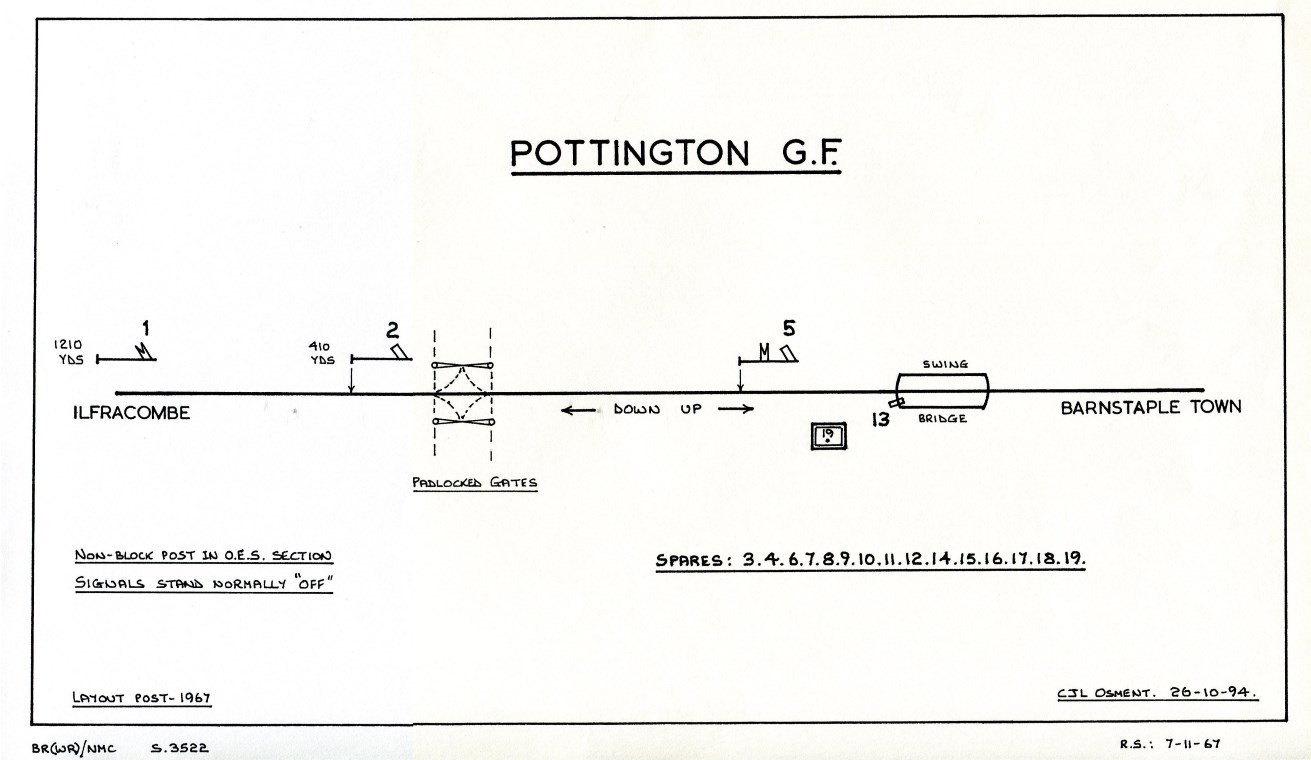
In 1923 the Ilfracombe line became part of the Southern Railway (SR) and then in 1948 it became part of British Railways (BR) and subsequently part of their Southern Region (BR(SR)). On 17-December-1967 the entire line from Pottington to Ilfracombe was reduced to single-track again. The signal-box at Ilfracombe was closed, Pottington signal-box was reduced to ground-frame status to control the swing-bridge only, and most of the other signal-boxes on the line were reduced to ground-frame status just for level-crossing control. Only Barnstaple Town signal-box remained as a block-post, with Electric Key Token working to Barnstaple Junction 'B' signal-box and One-Engine-in-Steam working (with a wooden train staff) for the remainder of the line to Ilfracombe. The entire line was closed on 5-October-1970, the last service train running on Saturday 3rd October.

A
totem sign at Barnstaple Town seen from a window
of the Last Train on the Ilfracombe line on 3rd October 1970
Details about the early signalling of the Ilfracombe line are very limited, with no diagrams known prior to 1881. In order to provide a reasonable overall picture of the relevant signalling installations during the life on the line it has been necessary to make certain deducations based on the contents of various documents such as Board of Trade (BoT) Inspection Reports, Working Timetables (WTT) etc. The author has drawn from work previously done by fellow members of the Signalling Record Society and other researchers and acknowledges their contributions with gratitude. Although it is intended to deal with Barnstaple Town, Barnstaple Quay and Pottington as separate locations as far as possible, the complex nature of the interaction between the three signal-boxes means that some aspects of their signalling and operation will require a common description for clarity.
When the Ilfracombe line was opened in 1874 it was single-track throughout, with passing-loops at Braunton and Mortehoe. Block working was by Train Staff & Ticket (TS&T) on the three sections Barnstaple Junction West - Braunton - Mortehoe - Ilfracombe, supported by the use of Preece's block instruments (but it is not known if they were the 1-wire or 3-wire version). In addition to the signal-boxes (SB) at those locations there were also SBs at Barnstaple Quay and Wrafton; these were intermediate block-posts, but not staff posts, in the Barnstaple Jcn West - Braunton section. (For more general information about the original signalling arrangements on the Ilfracombe line click here to see an extract from the 1874 L&SWR WTT.) The line from Braunton to Mortehoe was doubled in 1889, and then onwards from Mortehoe to Ilfracombe in 1891, whilst the line southwards from Braunton to Pottington was doubled in 1890. This left only the line from Pottington to Barnstaple Jcn West as single-track from 1891 onwards, until the entire length of double-track was reduced to single-track again on 17-December-1967.
In 1890 block working on the single-line Barnstaple Jcn West - Pottington section was by TS&T with a round red staff, but during the mid-1890s that was replaced by the Electric Train Tablet (ETT) system using Tyer's No 3 pattern instruments; it is believed, but not yet confirmed, that the change took place during 1895 (L&SWR Instruction 29/1895). The opening of the new Barnstaple Town signal-box in 1898 divided that section into two new sections Barnstaple Jcn West - Barnstaple Town - Pottington, both worked by No 3 ETT instruments. (It is probable that the instruments from the former Barnstaple Jcn West - Pottington section were re-used with new tablets for one of the new sections.) On 2-January-1910 (L&SWR Instruction 2/1910) the No 3 instruments on the Barnstaple Jcn West - Barnstaple Town section were replaced by the No 6 pattern with 'B' configuration tablets, although it is probable that these were the original tablets for that section as the same pattern of tablet fits both No 3 and No 6 instruments. The Barnstaple Town - Pottington section had 'A' configuration tablets.
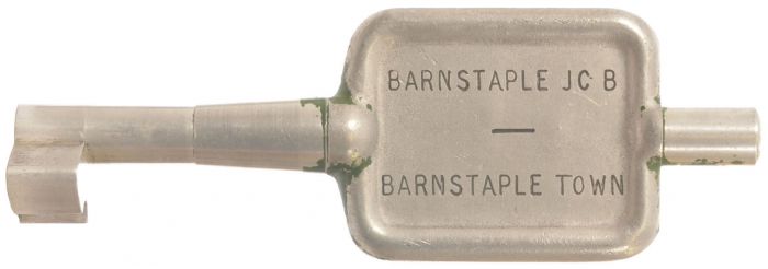
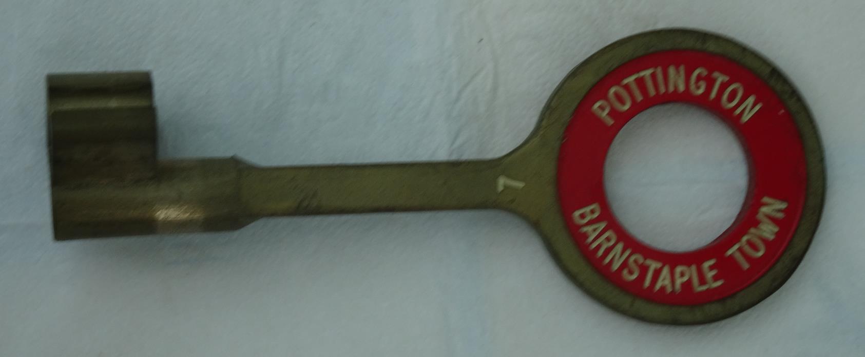
It would appear that at some date (probably in the early 1960s) there was a plan to replace the No 3 ETT instruments by Electric Key Token (EKT), as a number of BR(SR)-pattern key tokens labelled Barnstaple Town - Pottington exist in private collections, but there is no evidence that this alteration was ever implemented. When the line was rationalised in 1967 the No 6 ETT instruments were replaced by EKT using BR Western Region pattern equipment (with 'C' configuration tokens), while the new single-section from Barnstaple Town to Ilfracombe was worked under One-Engine-in-Steam regulations with a wooden train staff (round, red with an 'A' configuration Annett's key to unlock the ground-frames at Ilfracombe).
| Single-Line items from the British Railways era Click thumbnails to see larger images |
||||||||
 |
 |
 |
 |
 |
||||
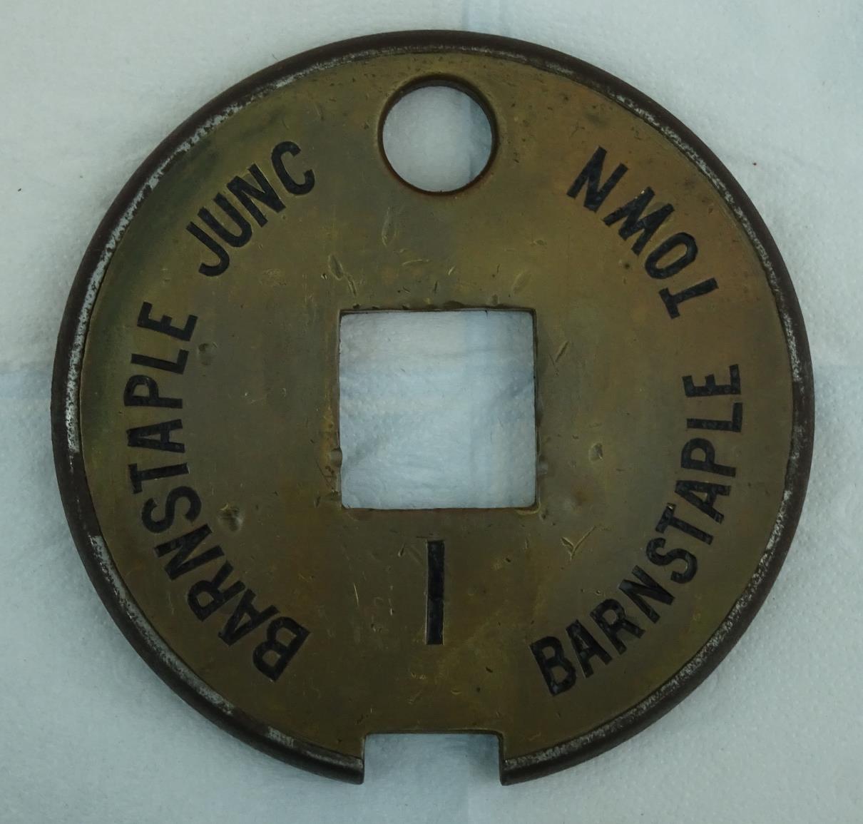
| No 6 Tablet | BR(WR) Key Token | No 3 Tablet | BR(SR) Key Token | Train Staff | ||||
| 1910-1967 | 1967-1970 | 1898-1967 | Never installed | 1967-1970 | ||||
Barnstaple Quay. This SB was a 2-storey L&SWR Type 1 box, located on the Down side of the line on the east side of the level-crossing from Commercial Road to the quay. When it was opened in 1874 it contained a 6-lever frame, which worked Distant, Home and Starting signals in both directions and a bolt on the swing-bridge at Pottington. Initially there was no interlocking with the level-crossing, which may not have had gates anyway (given the initial 'light railway' nature of that part of the line). As described above, it was an intermediate block-post (but not a staff post) within the Barnstaple Jcn West - Braunton TS&T section. When it was inspected by Lt Col Hutchinson on 15-July-1874 he requested in his Report that "the levers be rearranged so they are next to the signals they refer to", which would suggest that the lever-frame must have been subject to some subsequent alteration. When Hutchinson re-visited the line on 30-September-1874 he commented merely that the swing-bridge bolt "did not work well enough"; given that it was approximately 450 yards from the Quay signal-box to the swing-bridge, exactly how did that bolt work anyway?
According to instructions in the 1874 L&SWR WTT (click here to see full details), operation of the swing-bridge required the use of a key kept by the signalman at Barnstaple Quay SB. However it is not clear from those instructions whether the key was interlocked with the lever-frame in any way, nor what function it served at the swing-bridge. Before issuing the key the signalman was required to send the 'Obstruction Danger' bell-code to Wrafton and receive an acknowledgement, and also place and maintain all his signals at 'stop'; it would appear from a subsequent post-1881 signal diagram (see here) that the Quay SB controlled stop signals at both ends of the bridge.
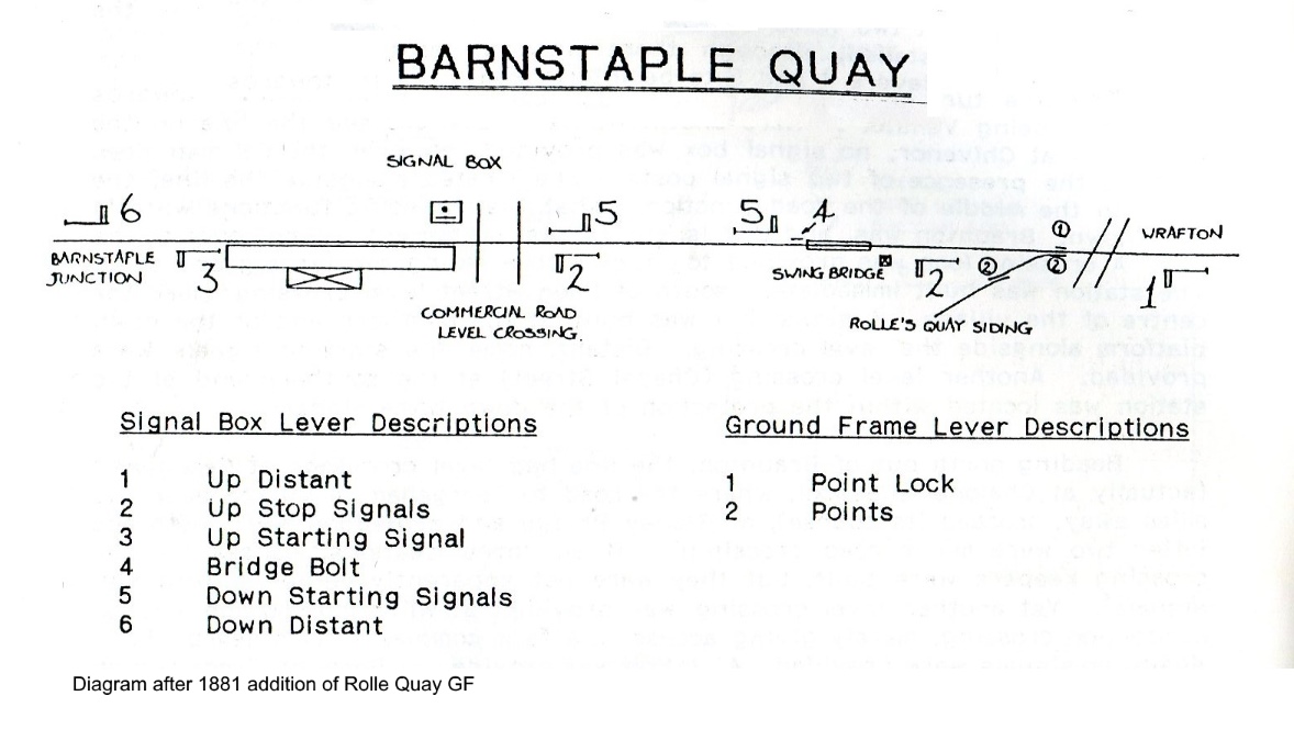
Rolle Quay Siding. In 1881 a siding was added on the Up side of the line west of the swing-bridge to serve Rolle Quay, the connection to the single line facing Up trains and worked from an adjacent 2-lever ground-frame (GF); a diagram for the new arrangements can be seen here. [Note: the drawing in the BoT file did not show V-notches in the ends of the distant signal arms.] The new GF was fitted with two Annett's locks, one unlocked by a key on the Barnstaple Jcn West - Braunton train staff and the other by a key from Barnstaple Quay SB (its removal from a lock in the SB locked the relevant signals). Although the new work appears not to have been inspected by the BoT until the 11th March that year, the L&SWR issued Instruction 36/1881 for the opening of the new connection on 23rd February, from which the following is an extract of the method of working:-
"An engine or train can only be sent to Rolle Quay when the Train Staff for the Barnstaple and Braunton section is at Barnstaple station....On leaving Barnstaple for Rolle Quay, the Guard will take the Train Staff.....and stop the train at Barnstaple Quay station and take from the signal box there the key of the Annett's lock in that box....The Warning signal from Barnstaple Junction to Barnstaple Quay and from Barnstaple Quay to Wrafton for a Train or Engine going to Rolle Quay will be 4 beats given twice...but the Ordinary Signals only will be used for Trains or Engines returning from Rolle Quay to Barnstaple Junction. Before any train can leave Barnstaple Quay for Rolle Quay, the obstruction Danger Signal, 6 beats, must be given to and acknowledged by Wrafton. On return of the Train or Engine to Barnstaple Quay, this signal will be cleared by the Error Signal, viz 7 beats....and the usual All Clear signal sent afterwards."
It would appear that, prior to the opening of Pottington SB in 1890 and hence the provision of run-round facilities, Rolle Quay was shunted as a 'trip' working to/from Barnstaple Junction and that the train was propelled all the way back to Barnstaple Junction.
 |
 |
|
| Barnstaple Quay diagram 1881 | Barnstaple Quay diagram circa-1895 | |
| Click either diagram thumbnail for a larger image | ||
In connection with the opening of Pottington SB in 1890 the lever-frame at Barnstaple Quay SB was extended from 6 to 9 levers, to provide locks on the gates which now existed on the Commercial Road level-crossing and on the second level-crossing to the quay which had been opened at an unknown date a short distance further west. Barnstaple Quay SB continued to have a bolt on the swing-bridge, but a second bolt worked by Pottington SB was added. When TS&T on the Barnstaple Jcn West - Pottington section was replaced by ETT probably (as described above) in 1895 the SB at Barnstaple Quay ceased to be an intermediate block post, but it continued to have a role in the operation of the single-line section because of its control over the swing-bridge. In simple terms, the signalmen at Barnstaple Jcn West and Pottington could not issue a tablet for a Down or Up train to pass through the single-line section until the signalman at Barnstaple Quay had taken the appropriate action to secure the swing-bridge and release their ETT instruments; detailed instructions can be read here. [Note: although the instructions refer to 'block instruments' at Barnstaple Town (formerly Quay) these were Sykes plunger instruments used to provide the necessary interlocking between various levers and the tablet instruments rather than for actual 'block working'.]
Shapland & Petter's Siding. In May 1890 a new siding was opened south of the River Taw bridge to serve the Shapland & Petter works (sited on the Down side of the line with a connection facing to Down trains). Although not directly related to the signalling at Barnstaple Quay, the BoT Inspection Report recorded that the GF at the new siding was unlocked by a key on the train staff (for the Barnstaple Jcn West - Braunton section). With the opening of Pottington SB in August 1890 and the doubling of the line to Braunton the single-line section was reduced to just the part from Barnstaple Jcn West to Pottington, but it continued to be worked by TS&T (L&SWR Instruction 84/1892). However after TS&T on the Barnstaple Jcn West - Pottington section was replaced by ETT probably (as described above) in 1895 the GF was unlocked by an Annetts' Key which was kept in the lever-frame at Barnstaple Jcn West box; this acted as a form of 'train staff' to authorise trains to proceed into the single-line section only as far as the siding and then return to the Junction, hence avoiding the need to withdraw a tablet from the 'non returnable' No 3 ETT instrument. Click here to read the instructions for working the siding which were issued in 1898 in conjunction with the opening of the new Barnstaple Town box (extracted from L&SWR Instruction 118/1898). This arrangement continued until the No 3 ETT instruments were replaced by the No 6 pattern on 2-January-1910, after which the GF was unlocked by the tablet.
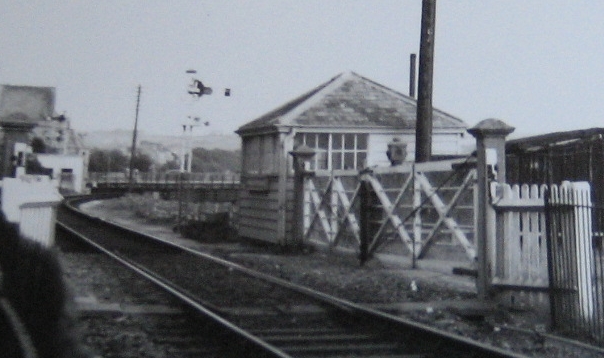 On 16-May-1898 Barnstaple Quay station and signal-box were superseded by the new
Barnstaple Town
station and signal-box built a short distance further down the line,
immediately west of the second level-crossing. Although it is clear from the
1898 film that the former Quay SB remained in use for a
short while thereafter, it was demolished eventually. In its place a
ground-level L&SWR Type 1 structure was erected to house a crossing-keeper for Commercial Road
level-crossing, now controlled from the new Barnstaple Town SB. It is
probable (although not proven) that this structure was constructed from
the upper storey of the old Quay box. Subsequent
details about this location are covered in the section below about the new
Town SB. The accompanying photograph shows the crossing hut in the British
Railways period (click photo for a larger image).
On 16-May-1898 Barnstaple Quay station and signal-box were superseded by the new
Barnstaple Town
station and signal-box built a short distance further down the line,
immediately west of the second level-crossing. Although it is clear from the
1898 film that the former Quay SB remained in use for a
short while thereafter, it was demolished eventually. In its place a
ground-level L&SWR Type 1 structure was erected to house a crossing-keeper for Commercial Road
level-crossing, now controlled from the new Barnstaple Town SB. It is
probable (although not proven) that this structure was constructed from
the upper storey of the old Quay box. Subsequent
details about this location are covered in the section below about the new
Town SB. The accompanying photograph shows the crossing hut in the British
Railways period (click photo for a larger image).
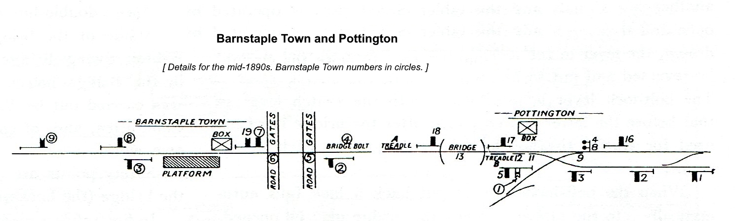
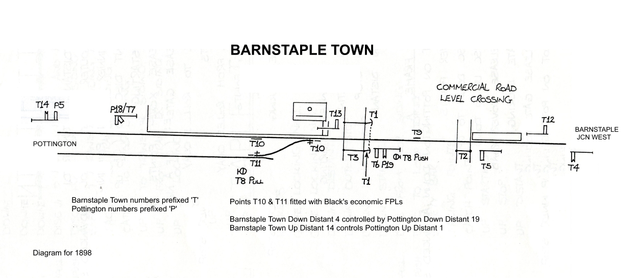
1898 Installation. The new Barnstaple Town signal-box and station were opened on 16-May-1898 (in conjunction with the opening of the Lynton & Barnstaple Railway), replacing the former Barnstaple Quay signal-box and station (L&SWR Instruction 118/1898). The new work was inspected for the BoT by Col Yorke on 4th May (L&BR installation) and 5th May (L&SWR installation), although his Report was not dated until 19th May. The new station had a single platform on the Up side of the single line, west of the Town level-crossing; the main (south) platform face served the Ilfracombe line, whilst a bay platform face on the rear (north) side served the L&BR. Not surprisingly, by virtue of the gauge difference, the L&BR was completely separate from the L&SWR and controlled by their own signal-box at the west end of the station - click here for more details.
The new brick-built L&SWR Type 4 signal-box was located at the east end of platform next to the level-crossing and contained a 14-lever Stevens-pattern frame; the diagram for the initial 1898 installation can be seen here. [Note: the diagram has been drawn the opposite way to the normal convention for ease of comparison with the Pottington 1898 diagram.] Lever 3 locked the gates at the adjacent 'Town' level-crossing, whilst lever 2 locked the gates at Commercial Road level-crossing. As discussed above, although it is clear from the 1898 film that the former Quay SB remained in use for a short while thereafter, in due course it was replaced by a ground-level L&SWR Type 1 structure to house a crossing-keeper. Later diagrams for the Town SB refer to that location as Ground Frame 'A', but it is not clear when that GF was provided or what function it served, as it would appear that lever 2 bolted the gates directly. It is known that a 1-lever frame was recovered from GF 'A' after closure of the Ilfracombe line, but it is possible that lever merely locked the smaller pedestrian gates adjacent to the larger road gates.
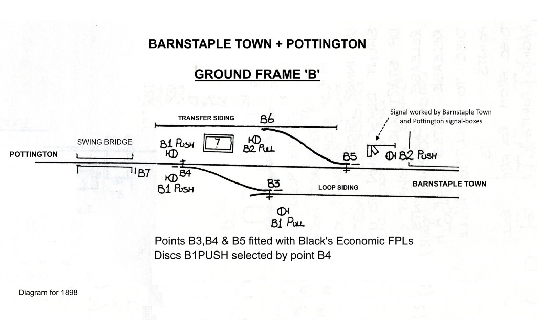
Immediately in front of the SB was a connection, facing to Down trains, into a loop siding on the Down side of the line. The west end of that siding had another connection to the single-line, facing to Up trains, immediately before the swing-bridge. At the Pottington end of the platform there was a connection on the Up side of the line, facing to Down trains, which served a transfer siding with the adjacent L&BR. Both sets of connections at the west end of the station and their associated ground-signals were worked from a new Ground Frame 'B', which had a ground-level 7-lever frame housed in a ground-level hut of the contemporary L&SWR pent-roof style (see diagram here). Although all the equipment worked by GF 'B' was located on the Town side of the swing-bridge, it was in fact released by Pottington SB. There are various references to GF 'B' in the records for both Barnstaple Town and Pottington, but most notifications of alterations list it under the former location. For the purpose of this page therefore GF 'B' will be discussed primarily in this section on Barnstaple Town rather than Pottington.
| Signal Diagrams for initial 1898 installation | ||
 |
 |
|
| Ground-Frame 'B' | Barnstaple Town Signal-Box | |
| Click any diagram thumbnail for a larger image | ||
In his Inspection Report Col Yorke expressed some concern about the fact that Down trains could enter the platform road while the swing-bridge at Pottington was unbolted, so he requested the provision of subsidiary 'Calling On' arms below both the Down Outer Home (5) and Down Inner Home (6) signals, with appropriate interlocking with the bridge bolt at Pottington SB. A letter from the L&SWR to the BoT dated 1-July-1898 confirmed that this work had been done, but in fact the L&SWR must have acted very promptly as both new signals were listed in L&SWR Instruction 118/1898 for the opening of the new signal-box on 16th May. (The new subsidiary arms can be seen in the 1898 film). At each of those two 'Home' signals the main and subsidiary arms were worked from the same lever, which was connected by a single wire to a 'selector' (probably a Sykes version) mounted on the signal post; when the signal lever (5 or 6) was pulled, then the selector governed which arm would lower to the 'off' position. The selector itself was controlled electrically by the bridge bolt lever (13) in Pottington SB; if 13 was normal (bridge bolted) then the main arm would be cleared, but if 13 was reversed (bridge unbolted) then the subsidiary arm would clear instead.
The new single-line sections Barnstaple Jcn West - Barnstaple Town - Pottington were equipped initially with Tyer's No 3 instruments, the change from the original single Barnstaple Jcn West - Pottington section actually having taken place on the preceding day (Sunday 15th May); it is probable that one of those sections re-used the instruments from the previous Barnstaple Jcn West - Pottington section but with new or modified tablets. There was also some Sykes interlocking provided with the two sets of ETT equipment to prevent the signalman at Barnstaple Town accepting trains from both Barnstaple Junction and Pottington at the same time. The instruments on the Barnstaple Jcn West - Barnstaple Town section were replaced by the No 6 pattern on 2-January 1910 (L&SWR Instruction 2/1910); that section had 'B' configuration tablets while the Barnstaple Town - Pottington section had 'A' configuration tablets.
 Later Alterations. On 8-January-1911 (L&SWR Instruction 23/1911) the existing Down
Distant signal (4) was abolished and replaced by a Distant arm mounted below
the Barnstaple Jcn West Down Advanced Starting signal and the Up Starting
signal (12) was replaced on a new post close by which also now carried the
Barnstaple Jcn West Up Branch Distant (its predecessor being abolished).
According to SR Signal Instruction (SI) 11/1923 the Up Starting signal
(together with the lower Distant arm for Barnstaple Jcn West) was moved 10½' closer to the SB on 30-May-1923 (SR
SI 11/1923) and eventually this signal was replaced by a new
rail-built post 18½' high close to its predecessor on 19-December-1949 (BR(SR) Notice P/EW 45W). Both Up and Down Distant signals
for Barnstaple Town were altered to have yellow arms and lights on 16-March-1928 (SR SI 9/1928).
Later Alterations. On 8-January-1911 (L&SWR Instruction 23/1911) the existing Down
Distant signal (4) was abolished and replaced by a Distant arm mounted below
the Barnstaple Jcn West Down Advanced Starting signal and the Up Starting
signal (12) was replaced on a new post close by which also now carried the
Barnstaple Jcn West Up Branch Distant (its predecessor being abolished).
According to SR Signal Instruction (SI) 11/1923 the Up Starting signal
(together with the lower Distant arm for Barnstaple Jcn West) was moved 10½' closer to the SB on 30-May-1923 (SR
SI 11/1923) and eventually this signal was replaced by a new
rail-built post 18½' high close to its predecessor on 19-December-1949 (BR(SR) Notice P/EW 45W). Both Up and Down Distant signals
for Barnstaple Town were altered to have yellow arms and lights on 16-March-1928 (SR SI 9/1928).
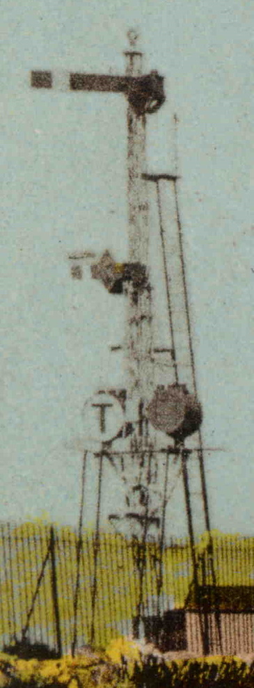
The Down Outer Home (5) was renewed on 21-July-1925 (SR SI 23/1925), at which time its subsidiary 'Calling On' arm was abolished. The previous lattice-post signal post (illustrated here, click for larger image) had carried circular 'C' and 'T' indicators for the permanent speed restriction over the Taw viaduct and these were re-fixed to the new post, but later abolished on 15-April-1931 (SR SI 13/1931). The Down Outer Home was renewed again on 5-October-1948 (SR SI 37/1948) on a 14½' high rail-built post. [Note: there is some undated photographic evidence which shows a second spectacle plate lower down on the post in the BR period. The reason for this is unclear, as there is no evidence to show that this signal ever carried any second arm after the 'Calling On' arm was abolished in 1925; one may speculate that it was preparatory work for some 1960s alterations which were never implemented.]
At GF 'B' there had been two ground-signals facing to Up trains, one each side of the single-line, which were both worked by lever 1PUSH in the GF (see 1898 diagram). These signals were 'selected' by the lie of the facing point leading into the loop siding; the right-hand signal read into the siding, the left-hand signal ahead towards the platform. According to SR SI 38/1926 on 14-November-1926 one signal was abolished and the other then worked for both routes; confusingly the SI wording is contradictory as to which actual signal remained, but the inference seems to be that it was the left-hand disc (on the Up side) which was removed. Subsequently SR SI 14/1945 (issued on 24-May-1945) recorded that the remaining ground-signal 1PUSH and also ground-signal 1PULL 'have been' abolished, but the exact date of change was not specified.
After the closure of the L&BR in 1935 the Transfer Siding served little purpose and eventually it was abolished on 3-April-1940 (SR SI 6/1940), along with its two ground-signals (2PULL and 2PUSH). Although GF 'B' point 6 was abolished, point 5 and its FPL were retained to act as a 'safety trap' whenever the swing-bridge was open, this point now leading to a new 40' sand-drag. [Note: some published drawings show the sand-drag in place at the same time as the transfer siding, but that is incorrect.]
There is photographic evidence that at some unknown date (if not in fact an original item) an additional 'flap' ground-signal, facing to Down trains and reading forward on the single line towards the swing-bridge, was installed in the 'six-foot' between the platform line and loop siding level with the Down Starting signal. This signal was fitted with slotting gear, indicating that it was controlled from two locations. Although it is possible that one of the slots was worked by the nearby GF 'B', there is circumstantial evidence to suggest that in fact it was worked by Barnstaple Town lever 7 (in addition to the Down Starting) and slotted by Pottington lever 14. This ground-signal was abolished on 8-July-1945 (SR SI 18/1945).
To be completed...
|
|
 |
|
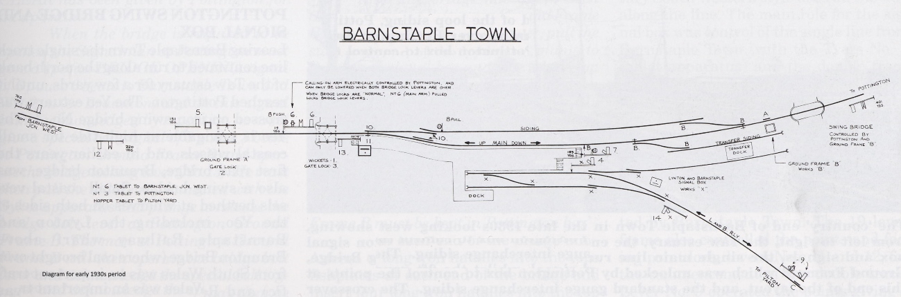
| Barnstaple Town diagram 1898 | Barnstaple Town diagram circa-1930s | |
 |
 |
|
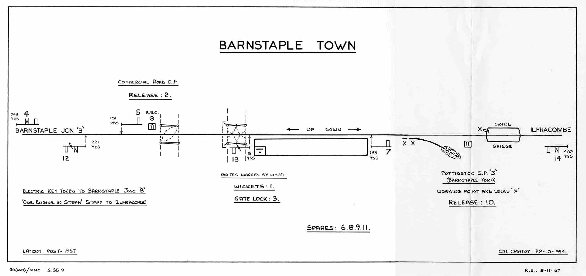
| Barnstaple Town diagram circa-1950s | Barnstaple Town diagram post-1967 | |
| Click any diagram thumbnail for a larger image | ||
1890 Installation. In 1890 Pottington was provided with a L&SWR Type 3B signal-box, with a timber superstructure on a stone base, which contained a 19-lever Stevens-pattern interlocking frame. It stood on the Down side of the line immediately west of the swing-bridge over the River Yeo, and it was opened on 4-August-1890 in conjunction with the doubling of the line from there to Braunton. The points for the single-to-double connection were located a short distance west of the SB, beyond which the access to Rolle Quay siding was altered to pass across the Up line by a diamond crossing and then trail into the Down line. Further down the line there was a level-crossing (for access to the foreshore of the River Taw), which was controlled by an adjacent ground-frame (later known as GF 'A'), and beyond that was a crossover also controlled by the GF. The GF had a 6-lever ground-level frame housed in a ground-level hut (similar to the L&SWR Type 3B style) located on the Down side of the line immediately on the west side of the level-crossing. It is unfortunate that there is no known signal diagram for 1890, but it is considered unlikely to have been very much different for the installation shown in the later 1898 diagram (except that GF 'B' did not exist yet). The new work was inspected for the BoT by Maj Gen Hutchinson and in his Report dated 21-August-1890 he requested that "No 4 semaphore signal at Pottington should be replaced by a ground disc", which would suggest that originally signal 4 had been provided as some form of main running signal. He asked also that there should be electrical interlocking to prevent the signalman from accepting a train from Wrafton when the swing-bridge was open, in the same way that existed already to prevent acceptance from Barnstaple Town (the former Quay box).
1898 Alterations. When the new Barnstaple Town signal-box and station were opened in 1898 some changes were made to the installation at Pottington, so the SB was inspected for the BoT by Lt Col Yorke on 5-May-1898 and the relevant diagram can be seen here. It would appear that GF 'A' had been extended to 7 levers, although the precise nature of the change is unknown, and that GF was released mechanically by levers in Pottington SB; lever 6 was the release for the crossover road, whilst lever 7 was the release for the level-crossing gates. Levers 4 and 6 in GF 'A' are not marked specifically on the diagram, but were the 'release levers' in the GF for the crossover road and the level-crossing gates respectively; for example, in order to use the crossover the signalman at Pottington would pull his lever 6, which would release lever 4 in the GF, which in turn would release crossover lever 2. A new 7-lever GF 'B' had been added to control various points and ground-signals at the west end of the new Barnstaple Town station, as well as taking over from the old Barnstaple Quay SB the control of the bolt on the east end of the swing-bridge. Although this new GF was on the Town side of the swing-bridge, it was released by electric plungers in Pottington SB; detailed information about this GF and its subsequent alterations can be found in the section on Barnstaple Town SB.
Block Working. When Pottington SB was opened in 1890 block working on the new Barnstaple Jcn West - Pottington block section was by TS&T (with a round red staff), but this was changed to ETT using Tyer's No 3 instruments in due course (probably in 1895 as described above). With the opening of the new Barnstaple Town SB in 1898 the ETT section was split then into two new sections Barnstaple Jcn West - Barnstaple Town - Pottington and the latter section was now worked by Tyer's No 3 instruments with 'A' configuration tablets. There was some Sykes interlocking provided with the ETT instrument to prevent acceptance of Down trains from Barnstaple Town when the swing-bridge was unlocked.
[Note: L&SWR Instruction 84/1892 provided information about the TS&T working on the Barnstaple Jcn - Pottington section. L&SWR Instruction 118/1898 dealt with the opening of the new Barnstaple Town station and signal-box and the two new single-line sections. It is curious that in both Instructions the Pottington location is described specifically as 'Pottington Level Crossing' but it unclear what, if any, significance should be given to that fact.]
Block working on the double-line section to Wrafton from 1890 onwards was probably by Preece's 3-wire 2-position instruments. However as part of the May 1898 alterations block working on the Up line only was changed to Sykes 'Lock & Block', with the appropriate Sykes 'plunger lock' instrument provided at Pottington for the purpose of accepting Up trains. The Sykes equipment provided the necessary electrical interlocking between the block system and the swing-bridge, to ensure that the signalman at Pottington could not accept an Up train from Wrafton if the bridge was unlocked. The Down line to Wrafton continued to be worked by Preece's 3-wire 2-position block, but with no switch-handle being provided at Pottington as this was the 'sending' end only. The mixed installation of Preece 3-wire and Sykes Lock & Block equipment was provided also on the Wrafton - Braunton section, so that the SB at Wrafton could be 'switched out' when not required as a block post, with the block section then becoming Pottington - Braunton without affecting the method of working.
Bridge Operation.
To be completed...
Later Alterations. At some unknown date the 'slots' worked by levers 1 and 7 in GF 'A' (on Pottington's Up Inner Home (3) and Down Advanced Starting (16) respectively) were abolished. Also at an unknown date the level-crossing gates were disconnected from the GF and simply padlocked across the roadway, with the result that Pottington lever 7 then became a spare. It is not known if both those changes occured concurrently, or at different times, but certainly they had taken place by 1947. On 24-January-1965 GF 'A' and its crossover points were taken out-of-use and its discs recovered (BR(WR) Weekly Notice K2/3/65).
As described in the section on Barnstaple Town above, there is photographic evidence of a ground-signal in the ‘six-foot’ between the platform line and loop siding at Barnstaple Town, level with Pottington's Down Home. This signal faced Down trains and controlled movements forward on the single line towards the swing-bridge; it was fitted with slotting gear, indicating that it was controlled from two locations. There is circumstancial evidence to suggest that it was worked by Pottington lever 14 and slotted by Barnstaple Town lever 7 (which also slotted Pottington's Down Home). This ground-signal was abolished on 8-July-1945 (SR SI 18/1945).
Both Up and Down Distant signals were altered to have yellow arms and lights on 16-March-1928 (SR SI 9/1928).
The Up Outer Home signal (2) was replaced by a new signal 14' high close to its predecessor on 25-May-1937 (SR SI 23/1937).
The Down Advanced Starting (16) was replaced by a new signal 14' high and 66 yards further from the SB on 28-September-1938 (SR SI 41/1938). On the same day the Up Distant (1) was replaced by a new signal 14' high and 69 yards further away from the SB, now being 800 yards from the Up Outer Home.
On 24-January-1965 Rolle Quay siding and points 9 were taken out-of-use and discs 4, 8 and 10 were recovered ((BR(WR) Weekly Notice K2/3/65).
To be completed...
 |
 |
|
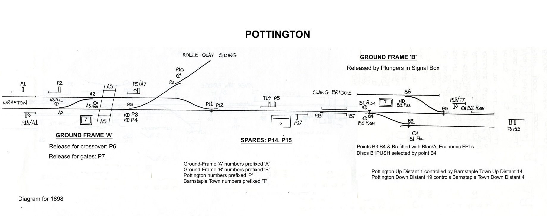
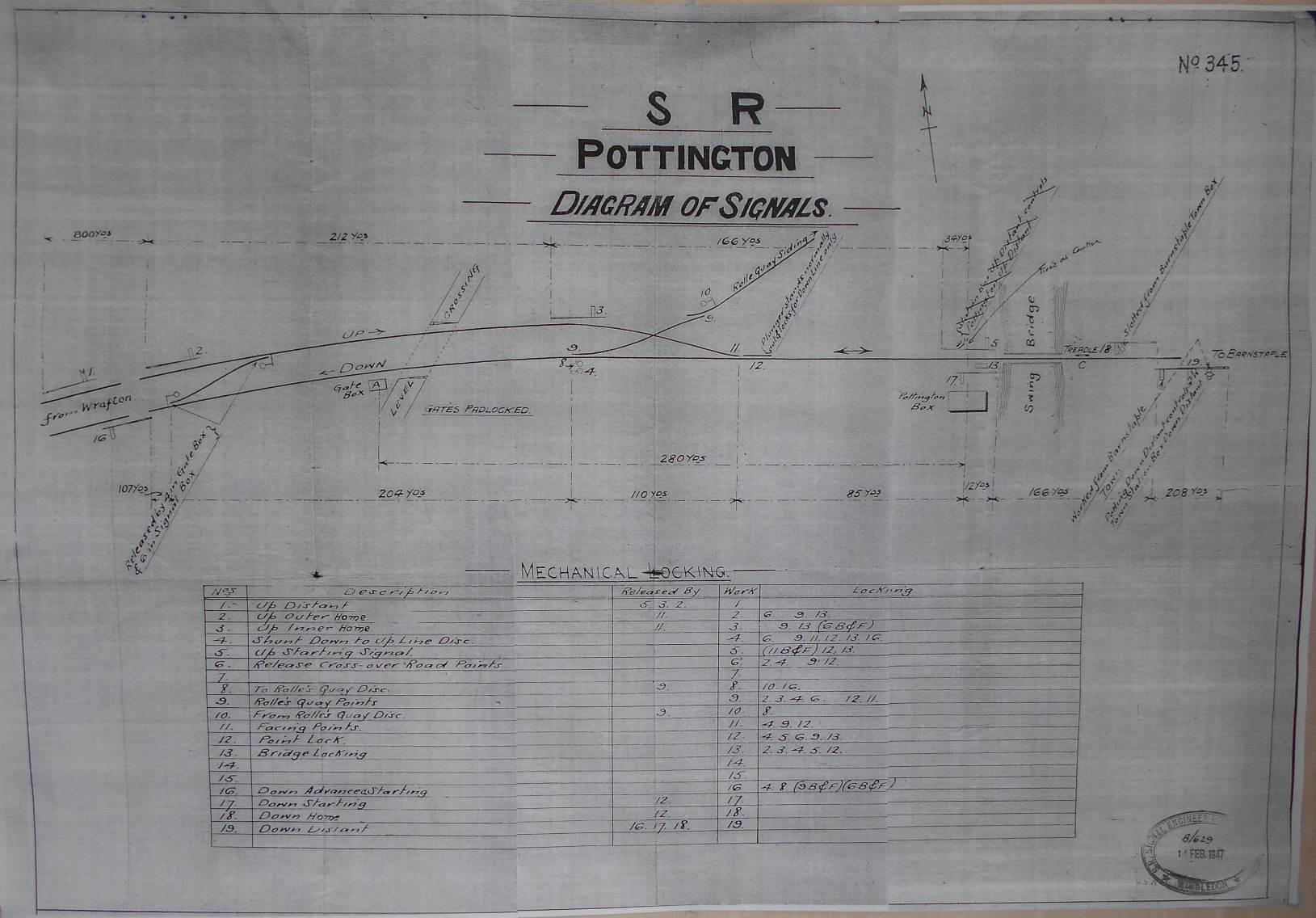
| Pottington diagram 1898 | Pottington diagram 1947 | |
 |
 |
|
| Pottington diagram 1961 | Pottington diagram post-1967 | |
| Click any diagram thumbnail for a larger image | ||
Miscellaneous Research Notes and Queries
1898 Film. In 1898 an unknown photographer shot some cine-film from the front of a train travelling on the line from Barnstaple Junction to Ilfracombe. Two sections of this film are known to exist, both of which can be viewed on YouTube (and possibly elsewhere). One section (viewable here) covers the initial part of the journey from Barnstaple Junction to Pottington, while the other section (viewable here) covers the final part of the journey into Ilfracombe station. The first clip shows a lot of the signalling installation at Barnstaple Town at that time, but often raises a few questions from viewers, so it is hoped that the detailed notes here will provide a useful explanation.
SR Signal Diagram. Some years ago the Signalling Record Society obtained a collection of microfilmed drawings from British Railways (Southern Region), which included a signal-box diagram for Barnstaple Town. At first glance this diagram seems to relate to the early Southern Railway period when the ex-L&SWR signal-box also controlled the L&BR, but a closer examination reveals that it contains various amendments from both the later SR period and also the BR period - long after the L&BR had vanished. There are inconsistencies within the drawing which suggest that it has been subject to incomplete amendments over a period of time, yet at the same time it yields some residual detail about earlier arrangements. It is considered therefore to be a useful resource, but not one on which to rely entirely. A copy of the diagram and a set of detailed comments can be found here.
Unexplained Rodding. All the points and FPLs etc worked by mechanical rodding from Barnstaple Town signal-box were concentrated at the east end of the station, whilst those at the west end were worked by GF 'B'. Therefore there was no known requirement for any rodding running from the signal-box to the west end of the station, as confirmed by most photographic evidence. Yet there are a number of photographs taken circa-1964 which show 4 sets of channel rodding emerging from the signal-box and heading towards the west end of the station on the down side of the line, mostly to the left of the space previously occupied by the loop siding. However photographs of the same area taken about 1960-70 show no sign of that rodding at all. So what was the purpose of this rodding, which seems to have existed only for a short period?
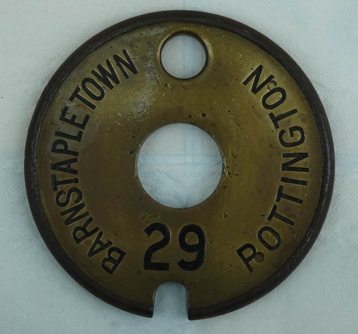
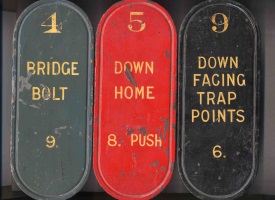
Although the full details are not known, there is some information available which would appear to relate to this mystery and from which a possible explanation can be proposed. On 9-July-1962 six replacement lever description plates for Barnstaple Town SB were ordered from the relevant BR(SR) works, as follows:-
| No | Description | Released By |
 |
|
|---|---|---|---|---|
| 4 | BRIDGE BOLT | 9 | ||
| 5 | DOWN HOME | 8PUSH | ||
| 6 | F.P.L. ON 9 | KEY TOKEN | ||
| 8PUSH | SHUNT TO LOOP SIDING | 11 | ||
| 9 | DOWN FACING TRAP POINTS | 6 | ||
| 10 | SIDING POINTS |
Three of those new plates are illustrated above. The details for levers 4, 6 and 9 would suggest that the intention was for Barnstaple Town SB to have direct control of the bridge bolt, trap point and FPL currently operated by GF 'B. Given the proposed new use for lever 6 then one may assume that the Down Inner Home (and its subsidiary calling-on arm) would be abolished, with shunt signal 8PUSH becoming a 'running shunt' to control movements forward on the platform line as well as into the Loop Siding. Furthermore the reference to lever 6 being released by 'Key Token' would suggest that this alteration was to be made at the same time as, or perhaps was the reason for, the proposed introduction of EKT working on the Barnstaple Town - Pottington section as a replacement for the No 3 ETT instruments. It is probable that the actual token release on 6 was to be done by a mechanical lock on the lever, so that the token would be retained in the lock until the bridge had been re-locked.
However some mysteries still remain about this work. It will be noted that the Loop Siding was to remain in use (points 10), so what was the intention regarding the exit from the siding at the west end? If that connection was still to be worked by GF 'B', then what was the benefit in transferring the other work from GF' B' to the SB itself? By the mid-1960s the swing-bridge was rarely opened, so would it have been worth the expense, especially as the siding connection probably had more use than the swing-bridge? But if the siding was to be disconnected at the west end, then why did the new plate for 8PUSH still refer to 'loop' siding, whereas the new wording for plate 10 now omitted the word 'loop'.
All the known photographs of the new rodding show it in place after the loop siding had been removed. Most of the rodding run is immediately adjacent to the railway's boundary fence, so it is possible that it could have been installed there while the siding was still in place. However there is at least one photograph which clearly shows that the eastern end of the rodding, where there were cranks for the rodding to cross under the single-line towards the SB, was in the space previously occupied by facing point 10. The new usage of levers 4, 6 and 9 would require 3 rods to the west end of the layout, so what was the purpose of the fourth rod that was installed? Was the planned work modified at some stage? It is unfortunate that no photographs are known which show the extreme western end of this rodding, so it is unclear to what it was intended to be connected.
It is presumed that, whatever the nature of the scheme, it was overtaken by the eventual decision to single the line to Ilfracombe. But it would be very nice to know exactly what the original plan had been!
© CJL Osment 2016-19
Acknowledgements to the
Signalling Record Society, Bob Palmer,
Graham Bowring and other contributors for archive information etc.
Train Staff photograph © Keith Jenkin, Tablets and
SR Key Token photographs © Richard Lemon, WR Key Token photograph courtesy
GCR Auctions.
References
|
© West Country Railway Archives 2016 Page last updated: 16 November 2019 |
URL: http://www.railwest.org.uk E-Mail: railwest@bigfoot.com |
||||||


