


 |
Lynton and Barnstaple Railway Signalling at Barnstaple Town |
|
||||||||
|
||||||||||
This page describes the signalling at Barnstaple Town station on the former narrow-gauge Lynton & Barnstaple Railway (L&BR). Please see the separate Introduction to L&BR Signalling page for general background information and details of other pages on RailWest about the signalling of the L&BR. Click here for more general historical details about the L&BR and a Bibliography.
 |
 |
|
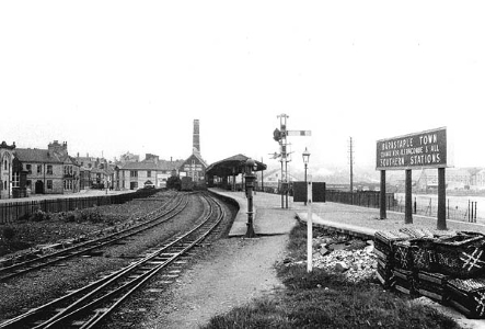
| Barnstaple Town station looking east - L&BR side on the left, L&SWR side on the right | ||
Barnstaple Town station was shared between the L&BR and the London & South Western Railway (L&SWR), which had a standard-gauge line from Barnstaple Junction to Ilfracombe. The station was opened by the L&SWR on 16-May-1898 in connection with opening of the L&BR, replacing an earlier L&SWR station of the same name (but originally called Barnstaple Quay) located a short distance nearer to Barnstaple Junction. In 1923 the new Southern Railway (SR) took over both the L&BR and the L&SWR, and the whole station came under common ownership.
Note: this page deals only with the narrow-gauge L&BR side of the station. There is a separate page in RailWest which deals with the standard-gauge L&SWR side of the station.
 The new Barnstaple Town station had a single long platform, which was on a
roughly south-east to north-west alignment. The south face of the platform served
the standard-gauge L&SWR line, whilst on the north face there was a long bay at
the west end which served the narrow-gauge L&BR line. L&BR trains ran 'Up' to
Barnstaple and 'Down' to Lynton. Alongside the bay
line there was a run-round loop, whilst a single siding - accessed from the bay
line by a point facing to Down L&BR trains - served a transfer location with an
adjacent standard-gauge siding off the L&SWR line. Some additional land adjacent
to the run-round line was earmarked apparently for a potential second L&BR
platform, but this was never constructed. The L&SWR and L&BR lines each had
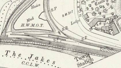
their own separate signal-box; the L&BR box is marked 'S.B' on the map, but the
L&SWR box was off the map to the right. The L&BR line to Pilton
curves away off the top of the map.
The new Barnstaple Town station had a single long platform, which was on a
roughly south-east to north-west alignment. The south face of the platform served
the standard-gauge L&SWR line, whilst on the north face there was a long bay at
the west end which served the narrow-gauge L&BR line. L&BR trains ran 'Up' to
Barnstaple and 'Down' to Lynton. Alongside the bay
line there was a run-round loop, whilst a single siding - accessed from the bay
line by a point facing to Down L&BR trains - served a transfer location with an
adjacent standard-gauge siding off the L&SWR line. Some additional land adjacent
to the run-round line was earmarked apparently for a potential second L&BR
platform, but this was never constructed. The L&SWR and L&BR lines each had
their own separate signal-box; the L&BR box is marked 'S.B' on the map, but the
L&SWR box was off the map to the right. The L&BR line to Pilton
curves away off the top of the map.
<<< A partial map of Barnstaple Town station surveyed in 1903
The original signalling equipment was installed by Evans O'Donnell (EoD), who were the L&BR's initial signalling contractor, although after 1922 some alterations or replacements were done by the SR using equipment of L&SWR or SR design. (Click here for more general information about L&BR signals.) On 4-May-1898 Lt Col HA Yorke inspected the L&BR on behalf of the Board of Trade and his subsequent Inspection Report contains some brief details about the signalling at Barnstaple, but unfortunately no numbered signal-diagram for Barnstaple (L&BR) has come to light yet so a number of un-answered questions remain about some features. The Inspection Report stated that there was a signal-box (SB) with an interlocking frame of 9 levers (7 working and 2 spares). The lever-frame worked the points and trap-points at each end of the run-round loop, the siding point and associated trap-point, and the three L&BR signals. During the independent L&BR period the SB also housed the Tyer's Electric Train Tablet (ETT) instrument for the single-line section to Pilton.
Signal Box.
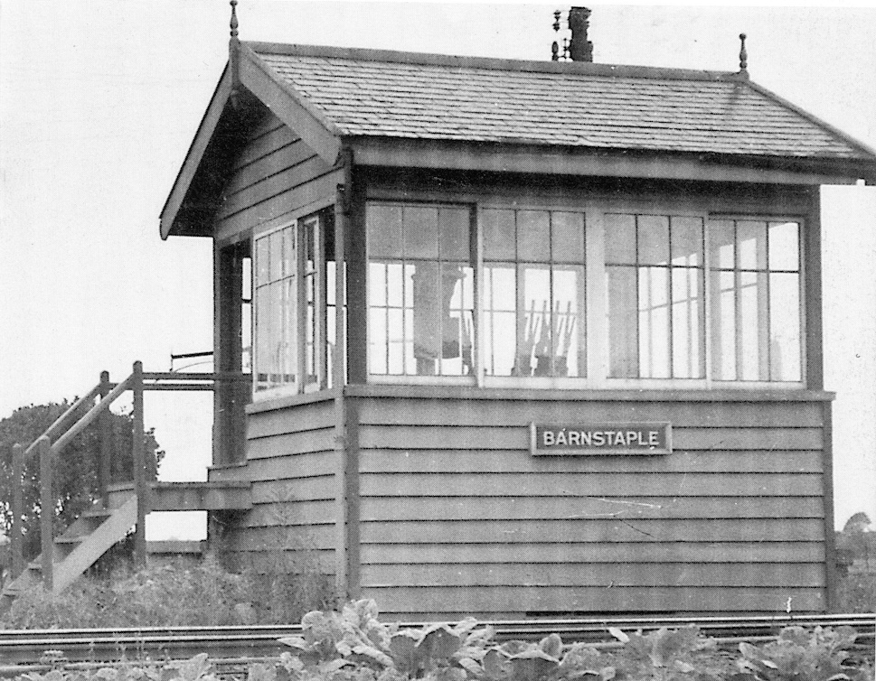 The L&BR SB at Barnstaple Town was an elevated wooden structure
to an EoD design (similar to the superstructure of the signal-box at
Pilton) and the picture shows the SB in 1935 (click for larger image).
There is some evidence to suggest that it was intended originally to build the signal-box
as a timber superstructure on a stone base, but in practice an all-timber
building was constructed which was supported on long piles sunk into the ground.
Somewhat unusually the upper part of the structure was fully glazed on all four
sides, which may have made it rather uncomfortable for the signalman on a hot
sunny day! One can only presume that the rear wall (facing the L&SWR
line) was glazed in order for the signalman to have a good view of the transfer
siding. The door was in the back left-hand corner, nearest to the station, and a
stove was sited in the rear right-hand corner. There was also a rectangular trapdoor in
the floor close to the middle of the rear wall which provided access to the 'void' under the operating floor.
Photographic evidence from 1909 suggests that the ETT instrument for the
single-line section to Pilton was placed against the middle of the wall at the Pilton end.
The L&BR SB at Barnstaple Town was an elevated wooden structure
to an EoD design (similar to the superstructure of the signal-box at
Pilton) and the picture shows the SB in 1935 (click for larger image).
There is some evidence to suggest that it was intended originally to build the signal-box
as a timber superstructure on a stone base, but in practice an all-timber
building was constructed which was supported on long piles sunk into the ground.
Somewhat unusually the upper part of the structure was fully glazed on all four
sides, which may have made it rather uncomfortable for the signalman on a hot
sunny day! One can only presume that the rear wall (facing the L&SWR
line) was glazed in order for the signalman to have a good view of the transfer
siding. The door was in the back left-hand corner, nearest to the station, and a
stove was sited in the rear right-hand corner. There was also a rectangular trapdoor in
the floor close to the middle of the rear wall which provided access to the 'void' under the operating floor.
Photographic evidence from 1909 suggests that the ETT instrument for the
single-line section to Pilton was placed against the middle of the wall at the Pilton end.
Lever-frame. The SB was equipped with a 9-lever EoD interlocking frame, mounted directly on the operating floor near the front of the box and supported by two large transverse joists. This lever-frame was essentially of the same EoD pattern as those supplied for installation at ground-level in the wooden huts used as SBs elsewhere on the L&BR and it was mounted directly onto the operating floor and supported by two large transverse joists. However, unlike the lever-frames actually used at ground level, the levers at Barnstaple Town had right-angled tails at their bottom ends, so that the down-rods to work the points and the wires for the signals could go vertically downwards through a long rectangular hole in the floor sited between the lever-frame and the front wall of the SB. It is presumed that the down-rods were attached to vertically-mounted pedestal cranks fixed to the ground in the 'void' under the operating floor, to which would be attached the horizontal rodding to the various points. Similarly the wires from the signal levers would have passed around vertical pulleys at ground level and then onwards to the various signals. It is not known if this hole was provided with any form of cover.
Signal Diagram. In the absence of any known official signal diagram, the outline diagram sketch below is intended to provide a general view of those features of the L&BR signalling which are known to have existed at Barnstaple Town. An Up Home signal was provided (marked UH on the diagram), as well as a Down Starting (DS) signal at the end of the platform and a Down Advanced Starting (DAS) signal further down the line towards Pilton. (Note: the lower ringed arm shown on the Down Advanced Starting was a later addition in 1927 - see the RailWest page about Pilton for more information.) The Down Advanced Starting was located close to Braunton Road Crossing and also served as the Down Home for Pilton SB, so it was 'slotted' by that SB - in other words, both the Barnstaple and Pilton signalmen had to pull their respective levers in order for the signal to come 'off'.

L&BR Signalling at Barnstaple Town
Note: The signal and point numbers and letters shown on the diagram are purely arbitrary and have been included solely for identification purposes within RailWest. Points given the same prefix letter (eg A1, A2) are assumed to have been worked from the same lever. It is known from surviving records that in the SR period lever 4 worked points 'A' and lever 8 worked the Down Advanced Starting (DAS).
In common with the rest of the L&BR the facing points on passenger lines were fitted with 'economic' Facing Point Locks (FPL), so at Barnstaple Town there were economic FPLs on points A1 and B1. There is detail in a diagram dating from the SR period to suggest that an economic FPL was fitted also to point C1, although the reason for that is unknown and there is a lack of any photographic evidence for it. The known features of the signalling at Barnstaple Town as depicted in the diagram above only account for 6 working levers (not 7 as stated in the 1898 Inspection Report), so the precise arrangement of the lever-frame remains a mystery. It is reputed that spare land was reserved alongside the loop line for a possible second platform, so it may be the case that the two spare levers were provided to cater for additional Up Home and Down Starting signals for that line, but the numbers of those spare levers are not known.
In 1923 the SR took over both the L&BR and the L&SWR. As far as it has been possible to determine, there had been very little change to the original signalling provided at Barnstaple Town prior to that date. Photographic evidence does show that, at some unknown date in L&BR days, the Down Starting signal was re-located to a position outside of the loop line. It remained there until 28-August-1929, when it was replaced by a new signal on the platform, which had a lower-quadrant (LQ) arm on a 12' high SR-style rail-built post (SR Signal Instruction No 33 of 1929). Also at an unknown date (before August 1926, but possibly after the SR take-over in 1923) the Down Advanced Starting was renewed as a L&SWR-style LQ arm on a wooden post with a ball-and-spike finial. The Up Home was replaced on 20-January-1925 (SR Signal Instruction No 2 of 1925) by a new lattice-post signal 11 yards nearer to Pilton.
It would appear that the SR embarked on a limited programme of rationalisation at Barnstaple Town after taking over the L&BR, mainly aimed at eliminating the need for two manned signal-boxes at the station, but no precise date for those changes has yet been determined. The Tyer's Electric Train Tablet instrument for the single-line section to Pilton was transferred from the former L&BR SB to the ex-L&SWR 'main line' SB, apparently by early 1925 (SR Instruction 4a of 1925), and the L&BR SB was down-graded to ground-frame (GF) status. Alterations to the standard-gauge signalling freed-up 3 levers in the ex-L&SWR SB, which were used then to work 'slots' on all three ex-L&BR signals, so that the 'main line' signalman now had control over the movements of L&BR trains to/from Pilton.
Under normal interlocking rules the lever for the Up Home signal would have locked the levers for the Down Starting and Down Advanced Starting signals and vice-versa, thereby preventing the signalling of conflicting movements. This interlocking was applied to the three new 'slot' levers in the main-line SB. It is assumed that the corresponding interlocking in the GF was removed, so that its three signal levers could be left in the reverse position when the GF was not in use and hence all its slots would normally be 'off'. Although it was now possible to send trains to, or receive trains from, Pilton without the GF being manned, it was still necessary to operate the GF lever-frame in order to work the various L&BR points (eg to run-round a train), as these were not connected to the main-line SB. It is recorded in a 1930 SR Appendix that the points for the loop and siding were unlocked by the tablet for the section to Pilton, and it known from other SR records that by late 1926 lever 1 in the GF was being used as a Release Lever (unlocked by the tablet) for the points.
In 1934 the Special Instructions for Barnstaple Town SB contained the following entry:-
| ||||||||
The same instructions also recorded that, for Block Regulation 4 purposes for the acceptance of trains from Pilton Yard, there was a modified clearing point 100 yards ahead of the L&B Up Home signal.
One other change which took place under SR ownership was the addition on 30-August-1927 (SR Signal Instruction No 22 of 1927) of a ringed arm below the main arm of the Down Advanced Starting signal (which also functioned as the Pilton Down Home). This signal was provided in conjunction with changes in working at Pilton rather than Barnstaple Town, and it is assumed to have been slotted from Barnstaple Town by the same lever as the main arm (it was the arrangements at Pilton which determined which arm came 'off'). It is believed that both arms had three slots, being worked jointly by Barnstaple Town (SR), Barnstaple Town (L&B) and Pilton signal-boxes, but the precise arrangements are unknown in the absence of any relevant records for that period.
There is evidence from various SR records that by 1927 there was an electric treadle located some distance in advance of the Down Advanced Starting signal towards Pilton; unfortunately there is no information available as to the purpose of that treadle or the date of its installation. Purely as speculation, it is possible that it was provided after the SR rationalisation (see above) to indicate to the SR signalman when a Down train had passed beyond the Down Advanced Starting and/or to release a back-lock on the relevant signal 'slot' lever. Unlike his predecessor in the L&BR SB, the signalman in the 'main line' SB would not have had sufficient visibility of the Down Advanced Starting signal to know when a departing Down train had passed beyond it towards Pilton, so he would need to know when it was safe to replace his 'slot' (and hence return Pilton's Down Home to 'on') without forcing the Down train to stop suddenly. There is some additional coverage of this matter in the RailWest page which deals with the standard-gauge L&SWR side of the station (see the comments about Treadle 'C' in the section about the SR signal diagram).
Postscript...
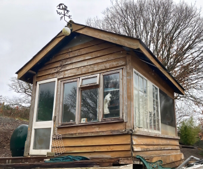 After
the closure of the L&BR in 1935 the wooden structure of the SB was sold to a private buyer and for many years it was used as a garden shed at a private
house in Umberleigh. During that during time it underwent various modifications,
including the removal of glazing in the rear wall. In 2023 the owner kindly donated the building to the
Lynton & Barnstaple Railway Trust (L&BRT) and its condition at that time can be seen in the photo on
the right here (click for larger image). The L&BRT are now restoring it as far as possible to its original form for display as a non-operational heritage relic
at a suitable location somewhere on the former railway. Occasional progress reports on this work can be found on the L&BRT's website
'blog'.
After
the closure of the L&BR in 1935 the wooden structure of the SB was sold to a private buyer and for many years it was used as a garden shed at a private
house in Umberleigh. During that during time it underwent various modifications,
including the removal of glazing in the rear wall. In 2023 the owner kindly donated the building to the
Lynton & Barnstaple Railway Trust (L&BRT) and its condition at that time can be seen in the photo on
the right here (click for larger image). The L&BRT are now restoring it as far as possible to its original form for display as a non-operational heritage relic
at a suitable location somewhere on the former railway. Occasional progress reports on this work can be found on the L&BRT's website
'blog'.
© CJL Osment 2004-25
Acknowledgements to Michael Bishop and the
Signalling Record Society
for archive information.
Colour photograph of the old SB in 2023 courtesy
Lynton & Barnstaple Railway Trust, OS map
extract reproduced with permission of the National Library of Scotland,
all other images WCRA collection.
| Interested in
the Lynton & Barnstaple Railway? Then why not join the Lynton & Barnstaple Railway Trust and help to re-build England's premier narrow-gauge line? |
| Introduction | Station Layout | Signalling | Signal Box | Lever Frame | Signal Diagram | Southern Railway Period | Treadle |
|
© West Country Railway Archives 2004 Page last updated: 03 July 2025 |
URL:
E-Mail: |
||||||


