


During the late 1960s, Hamilton city planners realized that a serious transportation bottleneck was in danger of forming. The rising population living in the new subdivisions on top of the escarpment (known to locals as Hamilton Mountain) would eventually overwhelm the limited number of routes connecting the southern part of the city with the downtown core. The completion of the Claremont Access in the early 1970s delayed this, but with only limited additional improvements and road widening possible due to the terrain, predictions showed all routes crossing the escarpment reaching maximum capacity in the early 1990s. As well, the bus routes crossing the escarpment would reach maximum practical capacity at around the same time. As the 1970s wore on, city planners began looking at mass transit options to prevent this gridlock. In 1976 They recommended the creation of a high volume transit corridor crossing the escarpment, connecting the downtown core with a suburban centre on the mountain.
In the early 1970’s, the Province of Ontario began work on a new type of transit system, the Intermediate Capacity Transit System, or ICTS. The ICTS was envisioned both as a method of filling in the capacity gap between low capacity buses and high capacity subways, and as a way to create a new industry in Ontario. Originally designed as a maglev on an elevated track, it evolved into married pairs (two cars permanently coupled together and sharing equipment, rather than each car being totally self-contained) of steel wheeled vehicles joined together in trains, with linear induction motors instead of the more traditional electric motors powered by an electrified third rail or overhead wire. The vehicles were driverless, and were controlled from a central facility. Testing, construction and sales of the ICTS was managed by the crown corporation Ontario Transportation Development Corporation (OTDC), later renamed UTDC (U standing for Urban).
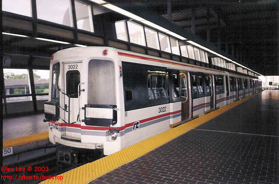
This four car train of the Toronto Transit Commission's Scarborough RT line shows what the Hamilton ICTS would have looked like. One major difference is the driver's cab, as the TTC did not want vehicles without drivers. (Photo by Alex Lee, used with permission)
By the late 1970s, UTDC and the province of Ontario had reached the point that a functioning large scale demonstration of the new technology was required in order to sell the ICTS to potential clients. (A prototype track would be built near Kingston in 1978) With the backing of the province, UTDC offered several large cities in Ontario the opportunity to be the home of the first ICTS, cities such as Hamilton and Toronto. UTDC took an early interest in Hamilton, because of the challenge of crossing the Niagara Escarpment. Studies undertaken in the mid 1970s by UTDC confirmed that ICTS was capable of crossing the escarpment.
On October 1 1978, at the opening of the Kingston test track, the Provincial government proposed that an ICTS system be built in both Toronto and Hamilton. The 6 kilometre line in Hamilton was originally estimated to cost $70 Million ($304 million in 2024 dollars). The federal government was approached by the province to contribute $30 million to the project, with the region of Hamilton-Wentworth paying $5 million and the province paying the remainder. Initial interest was high, and on December 19 the Hamilton-Wentworth regional transit commission sought a $3.5 million rapid transit study paid for by the province.
However federal funding for the proposal was not soon forthcoming, and the change of government after the election of a minority Conservative government in May 1979 caused the restarting of efforts. The fall of this government in December 1979 and the new election in March 1980 returning the Liberals to power delayed things yet again. And so on January 3 1980 the Province agreed to fully fund the $3.5 Million required for the study, claiming that it had received verbal promises from both parties. On August 12, 1980, the Regional Municipality of Hamilton-Wentworth entered into an agreement with Metro Canada Limited, a subsidiary of UTDC, to begin pre-implementation planning of a rapid transit system, connecting the downtown core with Hamilton Mountain.
Studies on factors such as ambient background noise, vibration, economic impacts, air pollutants, and transit use were conducted. Perhaps most interesting to the modern urban planner was a study comparing transit modes, to confirm the ICTS was the best one. A comparison was made between the proposed ICTS, an ICTS Subway, a Canadian Light Rail Vehicle (CLRV) in both mixed traffic and on a semi-exclusive right-of-way, regular buses in mixed and with rush hour bus priority lanes, trolley buses, and articulated buses. (Author's note: As this study was done by a company attempting to sell their own product, the fact that the proposed ICTS was ranked the best of all transit modes by the study should be taken with a grain of salt). These studies were estimated to take 15 months to complete.
It was decided early on that the then under construction Limeridge Mall would be the southern terminus for the ICTS. At the time, Limeridge Mall was fairly close to the east-west '50-50' line, with 50% of Hamilton Mountain's population living to the west of it, and 50% to the east. Hamilton's official plan had placed the HSR's then future bus terminal at Limeridge Mall, in order to act as a regional centre for the existing neighbourhoods, as well as the future subdivisions to the south. As well, a proposed football stadium was to be placed nearby at Upper Wentworth and Limeridge.
The initial phase of the planning study involved the creation of possible routes between downtown Hamilton and Limeridge Mall which was limited by the presence of the Niagara Escarpment. This resulted in the alignment options being split into three sections: Central, Escarpment and Mountain, with the boundaries being the TH&B tracks and the brow of the escarpment. Possible routes in one section would be joined with other possibilities in the other sections to form a complete route, but due to location not all combinations were possible.
All North-South routes on the mountain followed major roads, as there were no other possible routes that would not have major impacts on residential areas (i.e. expropriation, construction). There were four Mountain routes originally proposed:
As crossing the escarpment was the most difficult portion of the ICTS from an engineering point of view, 12 different routes were examined:
Routes E1, E7 and E10 were all eliminated before the selection process began: E1 had a maximum grade that was too steep, preliminary soil testing revealed that E7 passed through a section of the escarpment with poor soil conditions that would have made construction expensive, and E10 would have required a very long and expensive tunnel.
In the central Business District, emphasis was put on identifying potential station sites, rather than on route alignments. Using existing and planned land use patterns, commercial, residential and institutional uses, six locations were decided on in the CBD:
It was realized early on that it was not feasible for all of these locations to be serviced. Therefore it was decided to concentrate on the first four locations. The Jackson Sq/Gore Park area was selected as the priority, with all route options serving at least two of the four locations. The presence of large buildings and narrow streets limited the potential routes, resulting in 13 routes segments for the CBD.
Detailed analysis of these routes was performed with an eye on the following:
Support of Regional Planning Policies
Support of Goals and Objectives
Development Criteria-minimize impact on heritage areas, pedestrians, support development goals
Transportation Criteria-integration with existing bus and trolley routes, and with intercity buses and trains
Physical Criteria-not to exceed maximum slopes or minimum curve sizes, etc.
Engineering Criteria-costs, will the structures fit between existing buildings
Environmental Criteria-minimize impact on Niagara Escarpment, trees, groundwater, etc
The detailed analysis resulted in the following routes being eliminated:
Input was sought from the public, via multiple open houses. It was hoped that the detailed analysis would reduce the number of routes down to approximately 12, but this was not to be. Instead, a network of major alignment segments with multiple paths was created. In January 1981 the region of Hamilton-Wentworth accepted these generated routes. For further analysis, the routes were broken down into segments, in order for direct comparisons between one another. The segments were renamed, with no relation to the previous route labels. Segments L1 and L2 were added as a request from regional council due to public pressure, even though routes along Fennell had been eliminated at the initial stage.
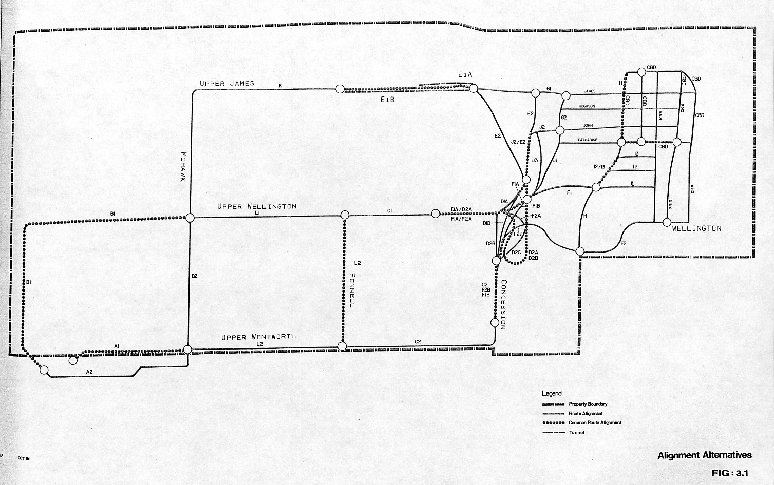
Map of Analyzed Segments. The white circles indicate attachment points between segments. (From Hamilton-Wentworth Rapid Transit Project, Draft Environmental Assessment, Metro Canada Limited, October 1981)
The segments were analyzed using 4 major criteria: Transportation, land use and environment, capital costs, and staging. The detailed analysis selected the following segments:
While the studies were being worked on, the region of Hamilton-Wentworth continued to press the federal government to contribute funding, as inflation had increased the estimated cost of the ICTS from $70 Million to $100 Million but the federal government had yet to openly state if they were going contribute
From the analysis 4 routes were created, which were approved by the Region on March 3, 1981:
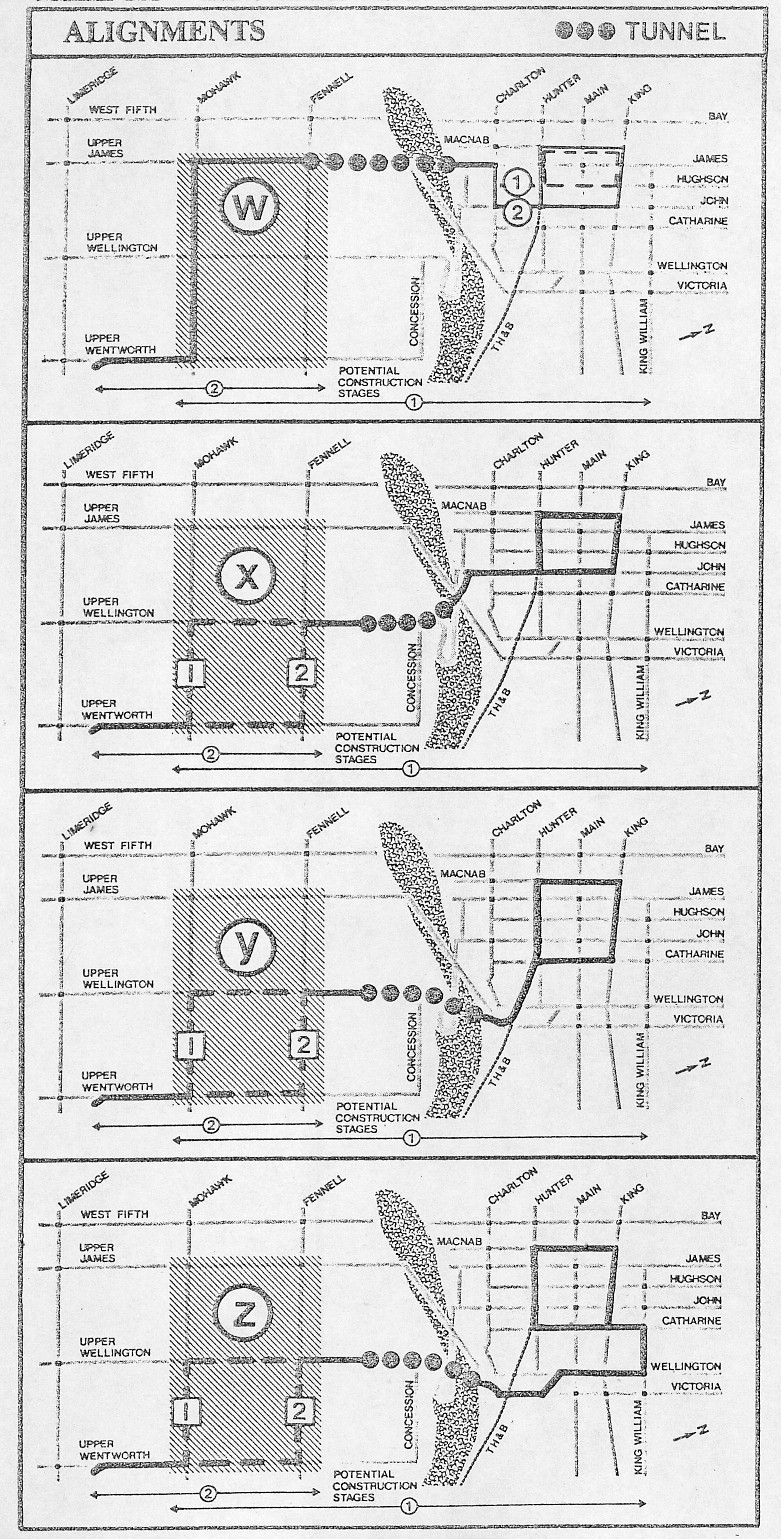
The 4 proposed routes, as approved in March 1981. (From Hamilton-Wentworth Rapid Transit Project, Draft Environmental Assessment, Metro Canada Limited, October 1981)
In all cases the CBD loop ran counter-clockwise, running along either John (routes W & X) or Catharine (routes Y & Z), and then King, MacNab and along the TH&B tracks back to the start point. Construction was proposed in two stages: The CBD one-way loop and escarpment crossing south as far as either Fennel or Mohawk, followed by an extension to Limeridge Mall.
Now with concrete plans for the ICTS on the table, local opposition to the proposed line began to gather. At the same meeting as the granting of approval of the 4 routes Flamborough Mayor Betty Ward objected, on the grounds that there was insufficient information and the population did not look like it would be high enough to warrant the line.
A series of open houses was held in Hamilton in mid-March to display the four options to the public and to gauge support. 57% of participants supported the ICTS project, with 26% opposed and 13% undecided. Of those who listed a preference for a route, 32% were in favour of W, 9% in favour of X, 20% in favour of Y, and 17% in favour of Z, with 22% having no preference or illegible. The meetings drew both supporters and opponents of the project, with many local residents concerned about the need for it, loss of property value and the use of Hamilton as a guinea pig for the ICTS.
On April 28 came the first serious knock against the ICTS, in the form of the Transportation Capital Facilities Plan, which stated that the population demand for an ICTS would not exist until the mid 1990s. On May 6 Connor Development Services, the company in charge of open houses and public outreach quit, stating that Metro Canada was failing to properly inform the public and politicians by not providing information on costs and environmental impacts. These two events resulted in several members of the regional council turning against the proposed route.
By May, further analysis had recommended that Route W be run along Hughson, and that routes X, Y and Z run along Mohawk. These recommendations did not eliminate the other options from selection. As well, the CBD one-way loop was routed over the city hall parking lot and over Jackson Sq to King William, and then south on Catharine in all cases. A followup series of open houses was held in late June 1981 to gather additional public opinion. At both the open houses and through a flyer mailed out to 50 000 homes, residents were asked to vote on their 1st and 2nd choice for preferred route, or on none of the above. Of 725 usable replies, 46% voted none of the above, 17% voted for W, 5% for X, 10% for Y, 14% for Z, and 8% gave no reply for their first choice. For their second choice, 47% voted for none of the above, 3% for W, 8% for X, 11% for Y, 10% for Z, and 21% gave no reply.
On June 16 a report by Metro Canada raised the estimate cost to between $131 and $143 Million depending on which of the 4 routes were chosen, with the additional track to Limeridge Mall costing between $18 and $32 Million of the total. A few properties would be required to be expropriated, including 1.4 hectares of parking lots. Of greater concern were the privacy issues caused by the elevated track, affecting 200 homes and 3 hotels
On July 16, 1981, Metro Canada made its final recommendation; that the ICTS be built along route W, and that the first stage of the construction end at Mohawk Ave. Route W was found to be the cheapest, have the lowest social impact on the mountain, and the only one to service the St Joseph's hospital/south James St Area. However, there were some construction impacts on the escarpment and the lower city that would have to be resolved. Total cost (land, construction, vehicles, etc) was estimated to be $111.1 million (approx. $353 million in 2024 dollars), with completion in late 1985/early 1986. The Hamilton regional Council accepted this recommendation on July 21, 1981.
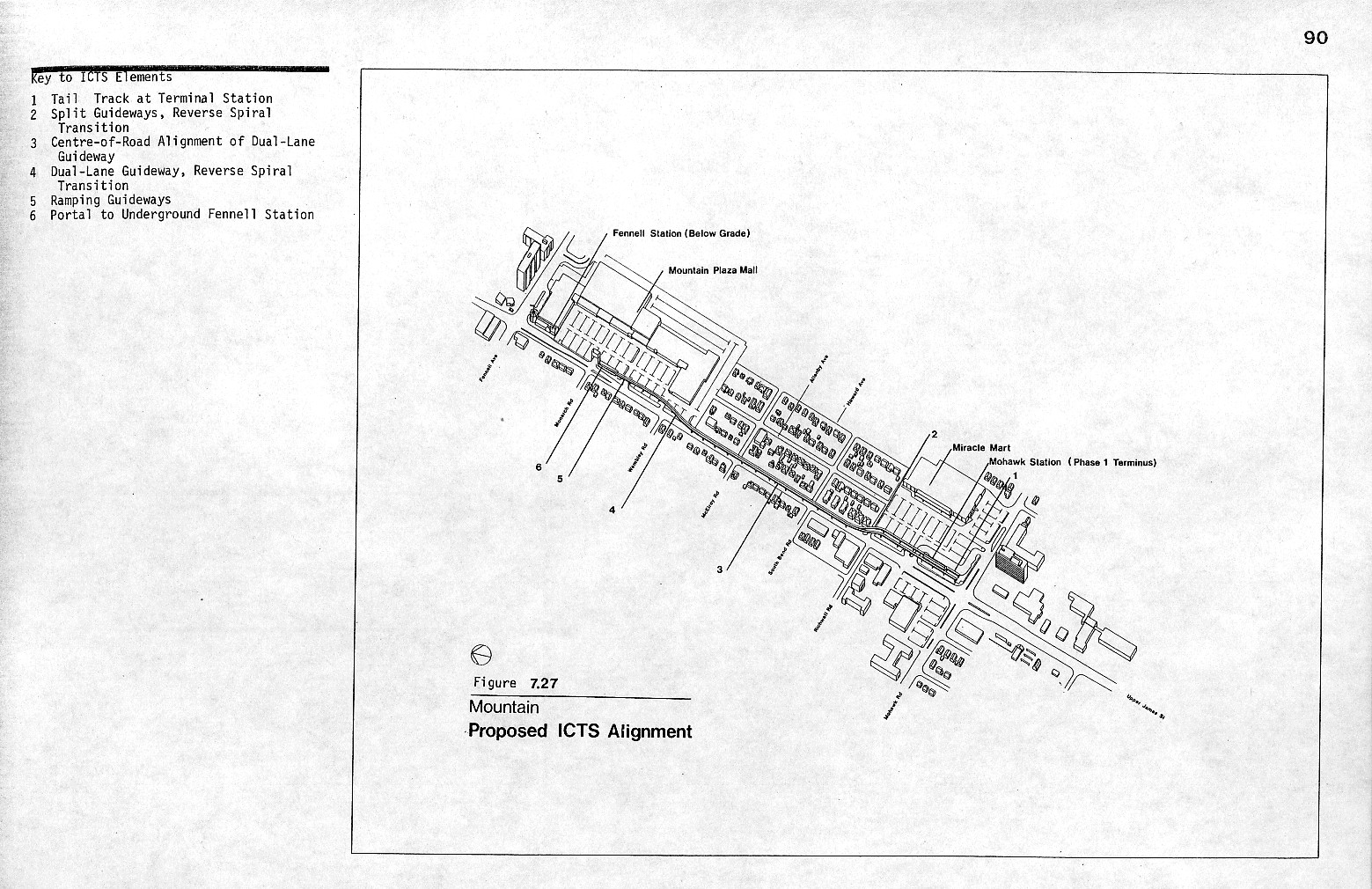
The ICTS line would have begun at the corner of Upper James and Mohawk, with Mohawk station on the northeast corner elevated above Mohawk Plaza. The line would head north on Upper James along the centre of the roadway, and then swing onto the side of the roadway, gradually descending until passing underground near the intersection of Upper James and Monarch Rd, on the parking lot of Mountain Plaza. Fennell Station would be located underground on the southeast corner of the intersection of Upper James and Fennell. North of Fennell station the ICTS would continue to descend until it emerged from the side of the Niagara Escarpment at the site of the old James St Incline, where the James St stairs are today.
View of ICTS along Upper James. (From Hamilton-Wentworth Rapid Transit Project, Functional Plans, Metro Canada Limited, October 1981)
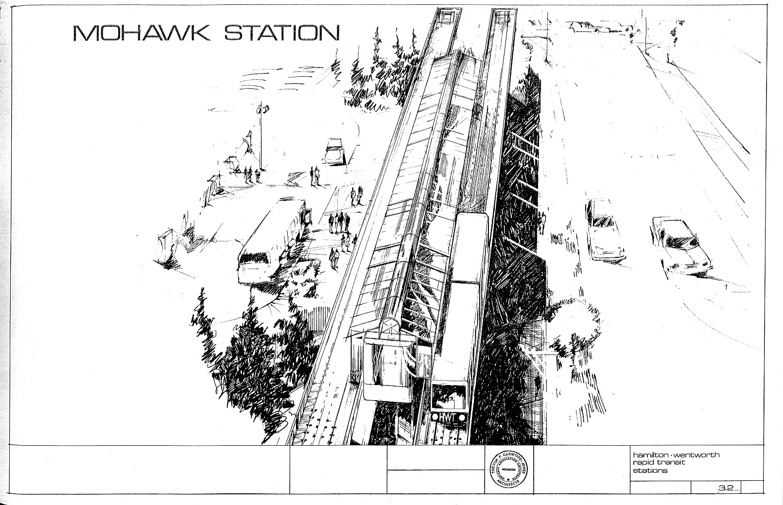
Artist's rendition of Mohawk Station. (From Hamilton-Wentworth Rapid Transit Project, Functional Plans, Metro Canada Limited, October 1981)
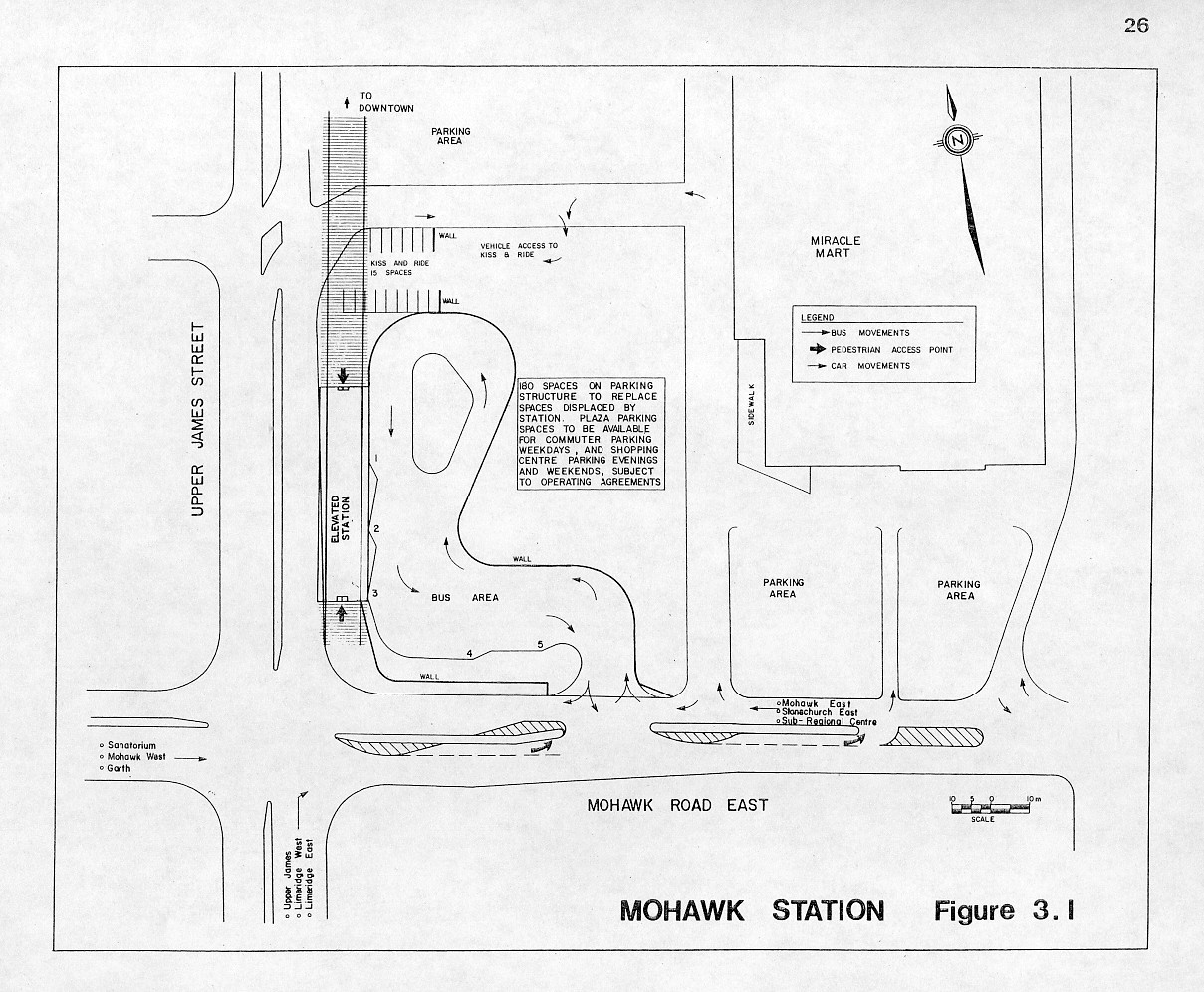
The intersection of Mohawk and Upper James, showing the station and the bus terminal in relation to the neighbourhood. (From Hamilton-Wentworth Rapid Transit Project, Functional Plans, Metro Canada Limited, October 1981)
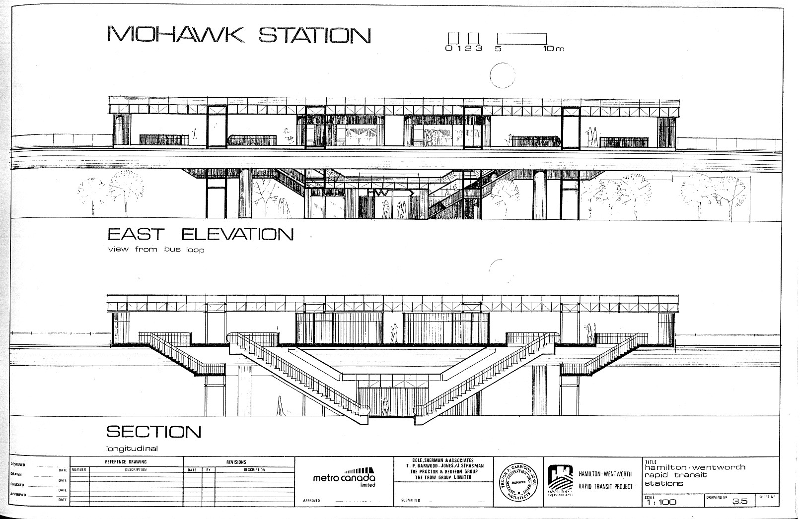
East Elevation View of Mohawk Station. (From Hamilton-Wentworth Rapid Transit Project, Functional Plans, Metro Canada Limited, October 1981)
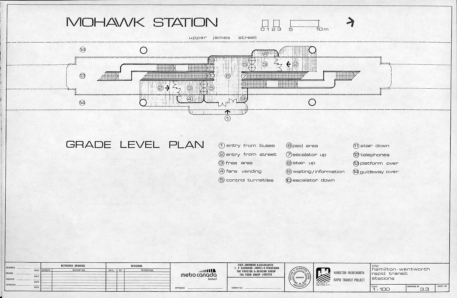
Plan of Mohawk Station at Ground Floor. (From Hamilton-Wentworth Rapid Transit Project, Functional Plans, Metro Canada Limited, October 1981)
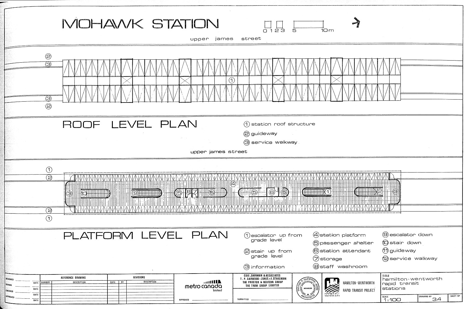
Plan of Mohawk Station at Platform and Roof Level. (From Hamilton-Wentworth Rapid Transit Project, Functional Plans, Metro Canada Limited, October 1981)
Now again on an elevated track, the line would have swung slightly east, to parallel James St South on the east side. The elevated line would have jumped from James to Hughson Street, either by cutting across the St. Joseph’s Hospital parking lot, or by making a sharp turn from James onto Charlton, and then another sharp turn from Charlton onto Hughson. St. Joseph’s station would have been located either on the southeast corner of James St and Charlton, or above Hughson Street at Charlton. These two sets of options were presented as St. Joseph’s hospital had not decided whether or not to allow the ICTS to cut across the property. At Hughson and Haymarket, right behind the TH&B station on Hunter St, the ICTS would have its maintenance facilities and storage yard, oriented east-west. This is also the location where the downtown one-way loop would begin.
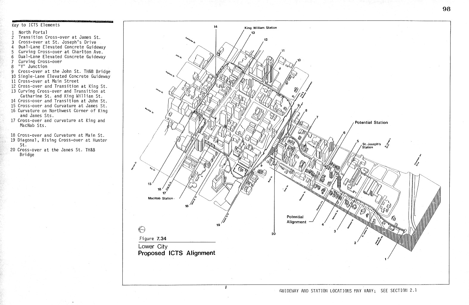
View of ICTS route in downtown core. (From Hamilton-Wentworth Rapid Transit Project, Functional Plans, Metro Canada Limited, October 1981)
Turning east, the one-way line would turn from Hughson, follow and pass over the TH&B tracks, and would head down Catherine St. It would turn onto King William St, and would run along King William to John St, where King William Station would be located. This first loop station was intended to serve the then Hamilton intercity bus terminal at John and Rebecca streets, and the east side of the downtown core. The line would continue on King William to James, where it would make a sharp turn to the south, running down James St on top of Jackson Square. It would turn sharply west at King, and then leave Jackson Square with another sharp turn onto MacNab and enter MacNab Station. MacNab station would be placed above the existing bus platforms at MacNab and Main, and would serve as the transfer point between the ICTS and the buses coming from the West end, as well as serving City Hall, Jackson Square, Copps Coliseum, and the Art Gallery of Hamilton. Heading south, then line would curve around Whitehern by passing over the Canadian Football Hall of Fame and the City Hall parking lots where it would turn east, cross over the TH&B tracks, and head up Hughson heading for St Joseph’s station.
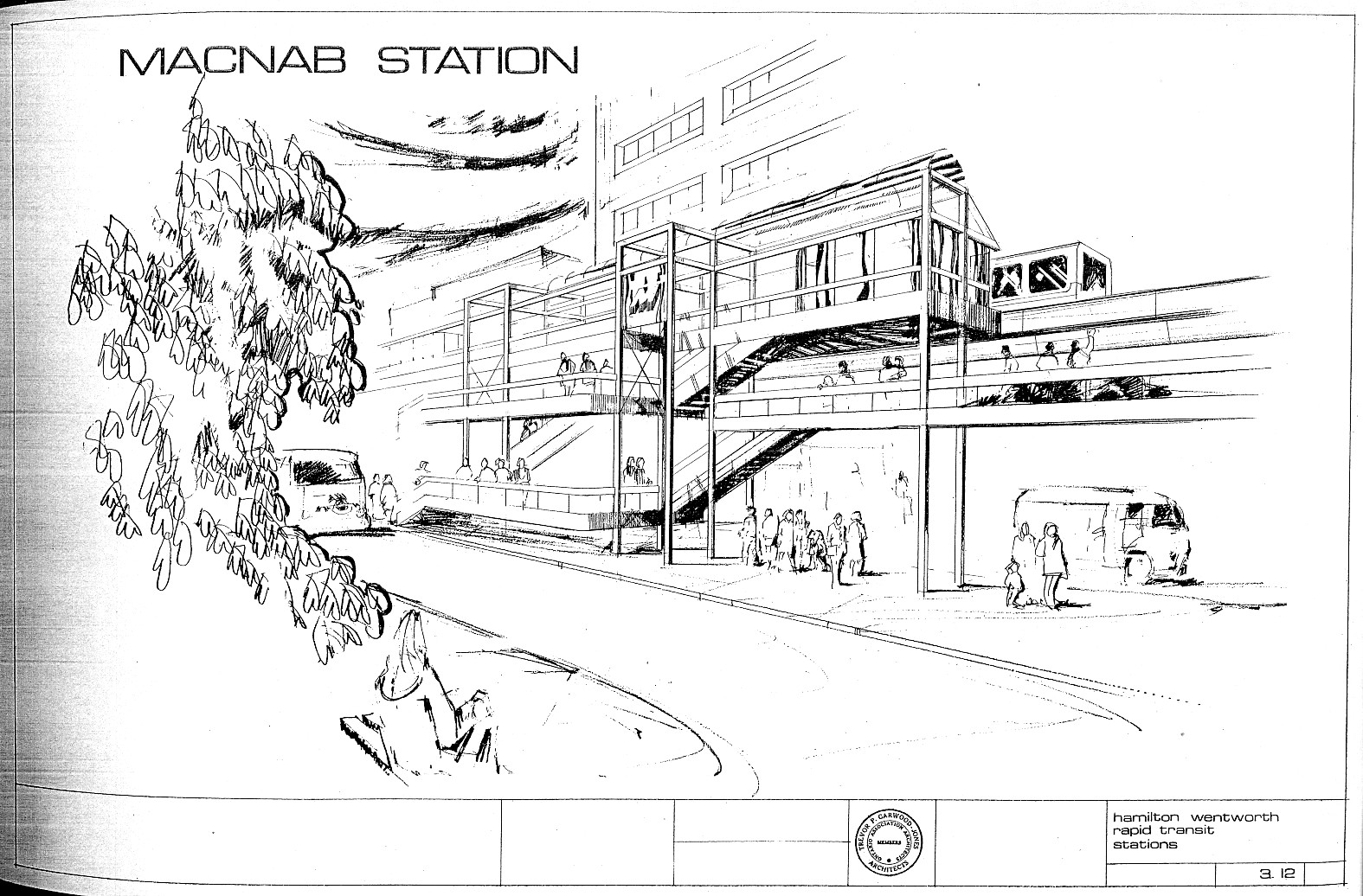
Artist's rendition of MacNab Station. (From Hamilton-Wentworth Rapid Transit Project, Functional Plans, Metro Canada Limited, October 1981)
The maintenance facilities and storage yard would be a two-storey affair, located right behind the TH&B Hunter St station. Heavy maintenance and vehicle delivery would occur at ground level, and at track level would be the storage yard and light maintenance (cleaning). A huge elevator, capable of moving a pair of ICTS cars, would lift or lower cars between the two levels. (As a side note, the presence of the ICTS yard would have meant that the Hamilton intercity bus terminal could not have been relocated behind the Hunter St station as it was in the 1990s)
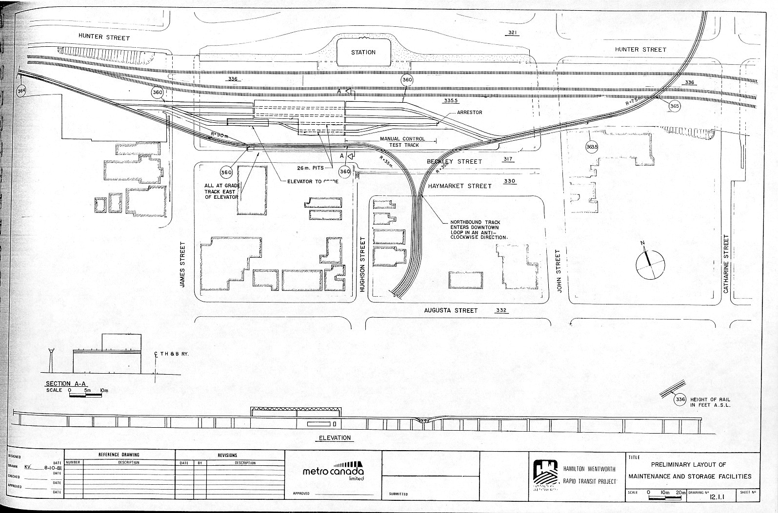
Map of ICTS Yard. (ASL stands for Above Sea Level) (From Hamilton-Wentworth Rapid Transit Project, Functional Plans, Metro Canada Limited, October 1981)
The creation of the ICTS would have altered the bus network on Hamilton Mountain dramatically, with most buses being routed towards an ICTS station, rather than the downtown core. Mohawk station would have had the largest bus station, with 7 routes redirected to the Mohawk station bus terminal. These would have included 27B UPPER JAMES, 32 GARTH, 33 SANATORIUM, 41 MOHAWK, and 45 LIMERIDGE, as well as a new STONECHURCH EAST route. Fennell Station would see the 27A UPPER JAMES, 31 FENNELL, 34 UPPER PARADISE, and 35 COLLEGE being rerouted to the new station, as well as new QUEENSDALE, UPPER WENTWORTH, and UPPER WELLINGTON routes created. St. Joseph station would have had no bus platforms, and MacNab station would have served all the routes that passed by Main & MacNab. King William station would see the 4 BAYFRONT rerouted via Wellington.
The announcement of the planned line resulted in the previous public opposition intensifying. Small businesses feared the impact to their bottom line due to construction. This opposition resulted in a decline in political support, as the July 21, 1981 acceptance only passed by one vote. Interestingly, much of the political support came from the rural parts of Hamilton-Wentworth. On August 18, Beak Consultants and B.W. Gillespie Associates took over the public outreach roll that Connor Development Services had walked away from.
On August 20 the Coalition on Sensible Transit (COST), a coalition of nine groups opposed to the ICTS, held their first public meeting. A fact sheet issued by Metro Canada on August 24 received heavy criticism as being biased and misleading in a council meeting on September 14. On September 18 the region's Social Planning and Research Council decided to oppose the ICTS on the grounds that the information provided was insufficient and the public participation was poor.
On September 29, a new regional planning document was released that now predicted that Hamilton-Wentworth would have a population of 445,000 by the year 2000, a decline from previous forecasts of 19%. This decline was large enough for politicians to not only call for the cancellation of the ICTS, but the highways now called the Red Hill Creek Parkway and the Linc. This prompted the environmental assessment for the ICTS to be restarted based on much lower population numbers. On October 17 an open meeting at the Hamilton Convention Centre draw large crowds criticizing the project and the political manoeuvring at the regional level.
Not everyone was opposed to the ICTS at this point however. The Hamilton Chamber of Commerce came out in support, and a survey released on October 22 put approval of the ICTS at 61%, but with most opposition coming from the areas closest to the proposed route. But on October 28 the federal government finally responded to months of funding requests, by saying that they would not commit to funding until after the region of Hamilton-Wentworth made a firm decision on the ICTS.
In early November the rapid transit study was completed and presented. It claimed that the ICTS will not cause an economic boom, but would make the city's future growth easier, with 600 jobs created as part of the construction. Noise levels would be noticable but not excessive. Property expropriation costs would be around $6 million, as much of the route would be on city property. One challenging feature would be the tunneling, due to the slope and potential instability. The study was quickly criticized because it was done using the previous population estimates
On November 5, St Joseph's hospital announced that the ICTS would interfere with the construction of a new hospital wing that was already in the advanced design stages, and requested that changes to the ICTS design be made. This was followed on November 27 with a formal letter stating that they did not want any part of the ICTS route crossing their property.
With multiple sources of opposition against the ICTS, political support for the project waned, to the point that the Hamilton Spectator reported on November 30 that it looked like the regional council would reject it. On December 10th the transit steering committee voted down the project 6-3, followed by the regional council voting no on December 15, 18-8.The province accepted the decision, and the allocated funds were returned to the general coffers.
The province of Ontario would go on to convert the proposed Scarborough LRT into the Scarborough RT, which ran from 1985 to 2023. ICTS technology would be also sold to Vancouver and Detroit. UTDC would eventually become part of Bombardier, and descendants of the original ICTS would end up in operation in Kuala Lumpur, NYC, and Beijing among others.
In the end the need for an ICTS or even additional roads down the mountain never materialized, as Hamilton's population never climbed as high as predicted in the 1960s and 70s. Planners in 1960 expected that what is now the old city of Hamilton would have a population of 438,000 by 1980. Instead it was 307,000 in 1981, and 40 years later in 2021 it was 343,000. With the drop in employment in the 1980s in Hamilton's industrial north, even less traffic than expected was going up and down the mountain.
Newspapers
Hamilton Spectator
"Horner silent on $135m transit plan" October 3, 1978, pg 8
"Valeriano welcomes transit experiment" October 11, 1978, pg 7
"Rapid transit project needs federal funds" October 18, 1978, pg 7
"The Mountain Express" October 28, 1978, pg 59
"City's transit 'showcase'" November 22, 1978, pg 7
"Transit study funds assured-Controller" December 21, 1978, pg 10
McGuinness, Eric "Beautiful whoosh replaces noisy clatter in new train" January 19, 1979, pg 7
"Ottawa may pay part of $70m" January 19, 1979, pg 7
"Province repeating plea for transit $" June 12, 1979, pg 7
McGuinness, Eric "Rapid transit decision soon: Foley" Novmeber 20, 1979, pg 10
"$3.5m approved for rapid transit study" January 3, 1980, pg 7
"Ottawa promised cash-Snow" January 4, 1980, pg 7
McNulty, Gord "Rapid transit plan promised" January 25, 1980, pg 7
Johnston, Bill "Proposed rail system 'complicated'" February 12, 1980, pg 8
McGuinness, Eric "Full speed ahead on transit plan says MacDonald" March 8, 1980, pg 7
"Office for transit project gets green light" April 17, 1980, pg 8
"Region is next stop for transit study" July 31, 1980, pg 7
"Rapid transit study pact official" August 13, 1980, pg 8
"3 plans for sports facilities" September 16, 1980, pg 7
"Rail line may be Christmas gift" October 4, 1980, pg 7
"What do you think about rapid transit?" October 22, 1980, pg 13
"Wheels turning on rapid transit plan" October 31, 1980, pg 10
Johnston, Bill "Decision on transit faces new council" November 7, 1980, pg 10
Johnston, Bill "Rapid transit system still on the track" November 22, 1980, pg 7
"Transit plan has go" December 8, 1980, pg 11
"Travel survey near end" December 20, 1980, pg 8
"Where Should the Rapid Transit Line Go" January 21, 1981, pg 13
"Meetings scheduled on rapid transit line" January 22, 1981, pg 10
"Region wants transit funds from Ottawa" February 13, 1981, pg 10
"Rapid transi system; Panel accepts 4 route plans" February 25, 1981, pg 10
"Tunnel through mountain 'cheaper'" February 27, 1981, pg 7
"Gray says there's no federal cash-yet" February 27, 1981, pg 7
"Rapid transit study off track, Ward warns" March 4, 1981, pg 8
"Residents question need for rapid transit line" March 17, 1981, pg 10
"Report says no urgency on rapid transit" April 29, 1981, pg 7
Sicoli, Florence "Costs come under attack; Transit dazzle fades" May 2, 1981, pg 7
Sicoli, Florence "Company quits rapid transit study project" May 6, 1981, pg 7
Sicoli, Florence "Information on transit plan withheld, consultant says" May 7, 1981, pg 7
Johnston, Bill "Public hearings suggested; Transit study change urged" May 9, 1981, pg 7
"Snow not aware of resignation" May 9, 1981, pg 7
"Transit plan hits rough road" May 15, 1981, pg 7
"Rapid transit load will fall on city" May 20, 1981, pg 7
"...But he has rapid transit warming up" May 21, 1981, pg 7
"Rapid transit study: A progress report to the people of Hamilton-Wentworth" May 21, 1981, pg 12
"Developers want to drive rapid transit point home" May 28, 1981, pg 10
"City's rapid transit still showpiece" May 30, 1981, pg 10
Hallman, Mark "Sloat claims public misled on transit" June 3, 1981, pg 7
Sicoli, Florence "Report details impact; Transit cost at least $131m" June 17, 1981, pg 7
"Rapid Transit Study: Route Choices" June 17, 1981, pg 18
Sicoli, Florence "The report on rapid transit; Costs remain key question over system" June 17, 1981, pg 21
Sicoli, Florence "Rapid transit information termed 'weak'" June 19, 1981, pg 7
Sicoli, Florence "City ratepayers face $11.75 hike for transit" June 22, 1981, pg 7
Sicoli, Florence "Reports jump gun on transit approval" June 24, 1981, pg 7
Allen, Susan & Sicoli, Florence "Rapid transit gets rough ride" June 25, 1981, pg 7
Sicoli, Florence "Rapid transit brochure bad publicity, Jones says" June 27, 1981, pg 8
"Federal transit funding sought" July 7, 1981, pg 8
Hallman, Mark "Report question City plan: Alderman" July 16, 1981, pg 10
Johnston, Bill "Panel picks cheapest rapid transit route" July 17, 1981, pg 7
"Survey results negative" July 17, 1981, pg 8
Harris, Wendy & McNeil, Mark "'Going to be a nightmare'; Transit route worries residents" July 18, 1981, pg 7
Johnston, Bill "Negative impact wasn't a factor, says consultant" July 18, 1981, pg 7
Sicoli, Florence "Transit route wins go-ahead by single vote" July 22, 1981, pg 8
Johnston, Bill "Projects will add $53 plus to tax bill" August 4, 1981, pg 7
"Transit study stays on track despite furor" August 19, 1981, pg 10
Sicoli, Florence "Coalition trying to put brakes on transit plan" August 20, 1981, pg 7
"Jones makes no apologies for transit system support" August 21, 1981, pg 7
Sicoli, Florence "Rapid transit; UTDC head surprised by dissent in Hamilton" September 3, 1981, pg 31
"Answer urged to transit fears" September 10, 1981, pg 10
Sicoli, Florence "Rapid transit study under attack" Septermber 11, 1981, pg 8
Sicoli, Florence "Transit fact sheet 'incredibly biased'" September 14, 1981, pg 7
Hallman, Mark "Rapid transit data a disgrace, McCulloch says" September 16, 1981, pg 10
Sicoli, Florence "Social planning council may move against transit plan" September 18, 1981, pg 10
Johnston, Bill "No support for rapid transit system" September 19, 1981, pg 8
Hallman, Mark "'We've been had'; Region predicts stunted growth" September 30, 1981, pg 1
"Transit foes renew fight with report" October 1, 1981, pg 10
"Population doubt; Transit projects studdied again" October 6, 1981, pg 7
"Chamber favors elevated system" October 6, 1981, pg 7
Sicoli, Florence "Transit survey called unreliable" October 9, 1981, pg 7
Pettapiece, Mike "Angry transit foes call meet a 'smokescreen'" October 19, 1981, pg 10
"Public in dark-transit report" October 22, 1981, pg 7
Mayers, Adam "Transit proposal favored by 61 per cent, says study" Ocotber 23, 1981, pg 7
McNulty, Gordon "Munro urges region to put transit on track" October 29, 1981, pg 10
Mayers, Adam "Transit surgery urged to take pressure off St. Joes" November 5, 1981, pg 10
Mayers, Adam "Impact study says: Transit system will boost future growth" November 6, 1981, pg 7
"'We have been flim-flammed'" November 6, 1981, pg 7
"Transit plan called the best" November 13, 1981, pg 7
Mayers, Adam "Transit noise no problem, study claims" November 13, 1981, pg 10
"Figures in reports on transit outdated citizens' group say" November 14, 1981, pg 7
"Rapid transit necessary, says developer" November 20, 1981, pg 8
"...Not so, labor says" November 20, 1981, pg 8
"Panel meets hostile audience on transit" November 23, 1981, pg 7
"Hospital has last word: No" November 27, 1981, pg 8
Mayers, Adam "Transit system may be axed survey shows" November 30, 1981, pg 7
"Alderman heckled for backing rapid transit" December 1, 1981, pg 10
"We don't want rapid transit council told" December 3, 1981, pg 10
Stewart, Bruce "No second chance on transit system" December 9, 1981, pg 7
Stewart, Bruce "It's now or never on transit-minister" December 9, 1981, pg 10
Mayers, Adam "Panel votes 6-3 to reject rapid transit" December 11, 1981, pg 7
"Munro regrets transit rejection" December 16, 1981, pg 1
Hallman, Mark "Rapid transit runs off track" December 16, 1981, pg 7
Pitkeathly, Doreen "What's next after rejection?" December 16, 1981, pg 7
Stewart, Bruce "Definite 'no' on other use for transit money" December 17, 1981, pg 7
Hallman, Mark "$3.5m study not a waste says Snow" December 17, 1981, pg 7
"Funding 'only for transit'" December 21, 1981, pg 7
Reports
Hamilton-Wentworth Rapid Transit Project
Task A-1: Rapid Transit Rationale. Marshall Macklin Monaghan Limited, Hatch Associates, Barton Myers Associates. December 1980
Analysis of Public Comments, Initial Open house Connor Development Services Limited, March 12, 1981
Task A-2: Generation of Feasible Alignments. Marshall Macklin Monaghan Limited, Hatch Associates, Barton Myers Associates. December 1980
Generation of Feasible Alignments, Cole Sherman & Associates. March 1981
Alignment Generation Criteria and the Generated Alignments, Metro Canada Limited March 13 1981
Alignment Evaluation Methods and Criteria for Shortlisting Alignments, M.M. Dillon Lmt, March 12 1981
Analysis of Public Comments and Ranking of Evaluation factors Connor Development Services Limited, March 12, 1981
Recommended Alignments and Summary Evaluation, Metro Canada Limited February 13 1981
Analysis of Public Ranking of Selected Alignments, Metro Canada Limited October 1981
Summary Evaluation of Rapid Transit Routes and Recommendation of Preferred Route, Metro Canada Limited, July 10 1981
Comparison of Alternate Modes. Marshall Macklin Monaghan Limited. November 5, 1981
Draft Environmental Assessment, Metro Canada Limited, October 1981
Functional Plans, Metro Canada Limited, October 1981


