


 |
Lynton and
Barnstaple Railway Electric Train Tablet Instruments |
|
|||||||
|
|||||||||
This page describes the Electric Train Tablet instruments used to control the single-line sections of the former narrow-gauge Lynton & Barnstaple Railway (L&BR). Please see the separate Introduction to L&BR Signalling page for general background information and details of other pages on RailWest about the signalling of the L&BR. Click here for more general historical details about the L&BR and a Bibliography.
When the L&BR was opened in 1898 the railway was divided into six separate single-line sections Barnstaple - Pilton Bridge - Chelfham - Bratton - Blackmore - Wooda Bay - Lynton, with a signal-box provided at each of those locations. [Note: sometime after opening Bratton was renamed Bratton Fleming, Blackmore became Blackmoor and Wooda Bay became Woody Bay. Pilton Bridge was known also as Pilton Yard or just Pilton.] From the outset all the single-line sections were worked by the Electric Train Tablet (ETT) system, which had been invented by Edward Tyer in 1878. At each end of each section there was an ETT instrument, the two instruments at opposite ends of an individual section being connected together electrically by a 'line wire' on a telegraph pole route alongside the track (the ground was used for an 'earth return'). Normally these instruments would be located in the signal-boxes at each end of the section, but because of the small size of most L&BR signal-boxes the ETT instruments were housed instead in the station buildings, except at Barnstaple and Pilton. After the Southern Railway (SR) gained control of the L&BR in 1923 the ETT instrument at Barnstaple Town was moved from the L&BR signal-box to the separate former London & South Western Railway (L&SWR) signal-box, which controlled the SR standard-gauge line to Ilfracombe.
The L&BR was equipped with the very rare Tyer's No 7A pattern of ETT instrument. Each instrument contained a number of 'tablets' - round metal discs engraved with the names of the signal-boxes between which they applied. No train was permitted to enter a single-line section unless the driver was in possession of a tablet for that section. The tablets were locked electrically within the instruments and a signalman could remove one to give to a driver only with the co-operation of the signalman at the other end of the section. Once a tablet had been removed from one instrument then both instruments for that single-line section were locked, so that no further tablets could be removed from either instrument until the first tablet had been replaced. This ensured that only one tablet for a section could be removed at any one time and therefore only one train could be in a single-line section at a time - obviously a critical safety factor. Normally when a tablet was taken out it would be carried through the section on the engine and then placed into the instrument at the far end, but in the event of a train failing to proceed then it was possible to return the tablet to the same instrument from which it had been removed.
Edward Tyer patented a series of different models of ETT instrument from 1878 onwards and at first the different patterns were identified by numbers:- 1, 2, 3 etc. Some patterns were modified at a later date and these variations were given letter suffixes, eg 5A, 6A etc. Tyer's instruments were sturdy, quality items well-suited to their purpose and it is a tribute to their design and construction that many still survive in the UK in private collections, on some heritage railways, and even a few in use by Network Rail (as at 2023). (Tyer's instruments were sold also to railways in other countries and it is believed that many still remain in use there.) However the early patterns were not cheap and it would appear that, with an upsurge in the construction of minor railways, Tyer turned his attention to producing designs that were mechanically and electrically simpler.
 After the introduction of the No 6 design
in 1892 Tyer started using different descriptions for his instruments
and this is where the identification situation gets confusing. In 1895 he
applied for Patent No 21,831 (granted in 1896) for an instrument which he
introduced in due course as an 'Automatic
Tablet Instrument', but this term - or variations of
it - was used subsequently also for other patterns of instruments. Then he
designed the No 7 instrument, which was based on the 'Automatic' but
intended for more general use, and this was patented by late-1898. Two sets of the
'Automatic' instruments were supplied to the Isle of Wight Central Railway by
1898 and these were described there as 'No 7A', even though in fact the No 7A
pre-dated the No 7. The term '7A' therefore has been adopted by most signalling
historians to describe the 1896 patent design in order to
avoid confusion with other 'automatic' instruments and to reflect
its similarity
with the more common No 7 instrument.
After the introduction of the No 6 design
in 1892 Tyer started using different descriptions for his instruments
and this is where the identification situation gets confusing. In 1895 he
applied for Patent No 21,831 (granted in 1896) for an instrument which he
introduced in due course as an 'Automatic
Tablet Instrument', but this term - or variations of
it - was used subsequently also for other patterns of instruments. Then he
designed the No 7 instrument, which was based on the 'Automatic' but
intended for more general use, and this was patented by late-1898. Two sets of the
'Automatic' instruments were supplied to the Isle of Wight Central Railway by
1898 and these were described there as 'No 7A', even though in fact the No 7A
pre-dated the No 7. The term '7A' therefore has been adopted by most signalling
historians to describe the 1896 patent design in order to
avoid confusion with other 'automatic' instruments and to reflect
its similarity
with the more common No 7 instrument.
Photographic evidence and surviving official records confirm that the L&BR was equipped with the No 7A pattern. Apart from the two sections on the Isle of Wight (later replaced by different equipment), the six sections on the L&BR are the only other sections known to have been fitted with this equipment. (There were a few single-line sections of the L&SWR recorded as having "automatic tablet instruments", but no firm evidence exists to prove that the L&SWR equipment was the No 7A pattern and all those sections had different instruments in later years.) The L&BR ETT instruments were described in a 1930 SR Appendix as 'Hopper No 1' instruments, but this was not a term known to have been used by Tyer. It is probable that, after the L&BR was taken over by the SR in 1923, this term was invented by someone in the SR simply in order to describe a type of machine previously unknown to them - it is unlikely that railway staff in Devon would have been familiar with equipment on the Isle of Wight.
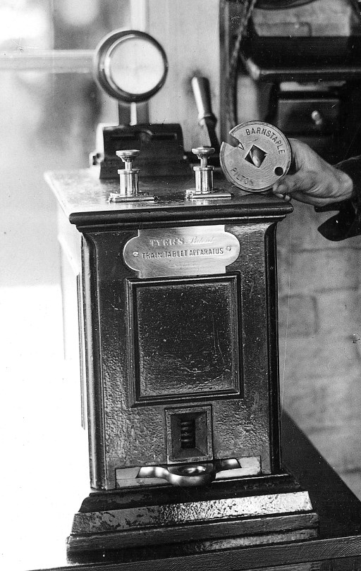
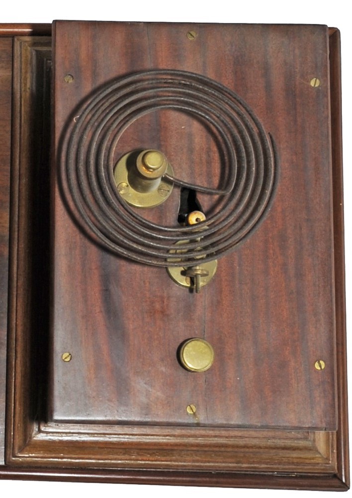
 The tablets
were stored within a vertical cylinder inside the front of the instrument
and the bottom tablet in the stack sat in a recess in a large horizontal
slide, which could be pulled out to release that tablet. There was a small
vertical 'window' in the front of the instrument so that the signalman could
see that there were tablets stored inside. Tablets were replaced into the
instrument through a slot at the rear of the top, inside which was a movable
half-drum - when this drum was rotated forwards and downwards by means of a
side lever the tablet was tipped out and slid down an inclined chute back to
the storage cylinder. On the top of the machine at the front were two plungers; the
'BELL' plunger (on the right) was used by the signalman for communication, while the 'SWITCH' plunger
(on the left) controlled the electro-magnetic lock on the slide. Unlike Tyer's
other designs of ETT instrument there was no indication provided of the
state of the instrument
(ie tablet 'in' or 'out').
The tablets
were stored within a vertical cylinder inside the front of the instrument
and the bottom tablet in the stack sat in a recess in a large horizontal
slide, which could be pulled out to release that tablet. There was a small
vertical 'window' in the front of the instrument so that the signalman could
see that there were tablets stored inside. Tablets were replaced into the
instrument through a slot at the rear of the top, inside which was a movable
half-drum - when this drum was rotated forwards and downwards by means of a
side lever the tablet was tipped out and slid down an inclined chute back to
the storage cylinder. On the top of the machine at the front were two plungers; the
'BELL' plunger (on the right) was used by the signalman for communication, while the 'SWITCH' plunger
(on the left) controlled the electro-magnetic lock on the slide. Unlike Tyer's
other designs of ETT instrument there was no indication provided of the
state of the instrument
(ie tablet 'in' or 'out').
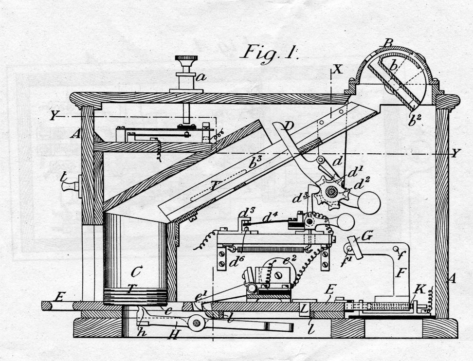
There was a polarised relay in the control circuit for the slide lock which is not shown in the patent drawings, so it is assumed that it was incorporated within the separate bell in a similar fashion to Tyer's earlier No 5 and later No 7 designs. The patent does not mention any galvanometer (to indicate the passage of electric current between the two machines), but an illustration of the instruments in an Instruction issued by the L&BR in 1898 does show one located behind the drum, as can be seen in the photograph above. It may be the case therefore that the actual instruments provided to the L&BR differed in some detail from the design shown in the patent. Click here to see more of the 1896 patent drawings.
 The bell was a separate item from the actual ETT instrument
and on other railways it was mounted usually on the wall, or a shelf, close to the ETT
instrument. (The author is not aware of any photographs which show a L&BR
installation.) It was Tyer's practice, at signal-boxes which communicated with
two adjacent signal-boxes (eg passing-loops), to provide a bell in one
direction and a gong in the other direction for easy distinction between
the sounds of the two devices. (A 'gong' had a large coiled spring rather
than a dome as the sounding device; the picture shows a typical example,
although not of L&BR origin.) It would appear that Tyer's normal
practice was to install a gong at the Down end of a section and a bell at
the Up end of the same section, so for example at Chelfham
there would have been a gong working to a bell at
Pilton and a bell working to a gong at
Bratton Fleming. An early L&BR document states
simply that "...the bell applies to Up trains and the gong to Down trains...",
although of course both the bell and gong would have been
involved in the passage of a train through a passing-loop from one section to the next.
The bell was a separate item from the actual ETT instrument
and on other railways it was mounted usually on the wall, or a shelf, close to the ETT
instrument. (The author is not aware of any photographs which show a L&BR
installation.) It was Tyer's practice, at signal-boxes which communicated with
two adjacent signal-boxes (eg passing-loops), to provide a bell in one
direction and a gong in the other direction for easy distinction between
the sounds of the two devices. (A 'gong' had a large coiled spring rather
than a dome as the sounding device; the picture shows a typical example,
although not of L&BR origin.) It would appear that Tyer's normal
practice was to install a gong at the Down end of a section and a bell at
the Up end of the same section, so for example at Chelfham
there would have been a gong working to a bell at
Pilton and a bell working to a gong at
Bratton Fleming. An early L&BR document states
simply that "...the bell applies to Up trains and the gong to Down trains...",
although of course both the bell and gong would have been
involved in the passage of a train through a passing-loop from one section to the next.
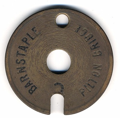
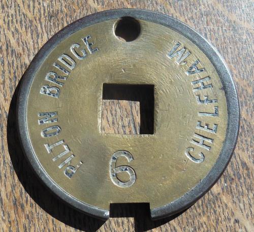
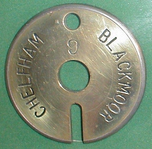
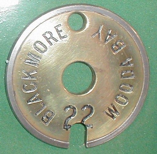
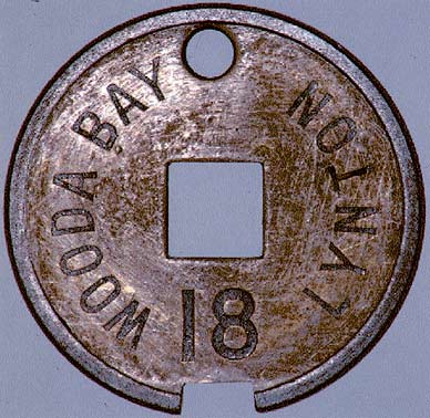
The tablets for Tyer's No 7A instruments were round metal discs approximately 4" in diameter, engraved with the names of the signal-boxes between which they applied. (Typically the tablets were either solid brass, or steel with a brass face-plate.) To ensure that a tablet for one section could not be placed incorrectly into the instrument for an adjacent section, each tablet had a 'configuration' which was achieved by a shaped notch in the edge of the tablet. This notch engaged with an equivalently-shaped nib at the back of the slot inside the receiving drum of the tablet instrument. In the centre of each tablet there was a hole, whose shape denoted the configuration for easy recognition:- round for 'A', square for 'B', triangular for 'C'. There was also a smaller hole (about 5/8" diameter) diametrically opposite the notch, although this appears to have served little function other than for the signalman to insert a finger when trying to get the tablet out of the instrument slide! The 1896 Patent does show a small 'knob' on the front of the instrument on which a tablet could be hung by that small hole after removal from the slide, but it appears to have been omitted from the L&BR machines. In each section the tablets were numbered individually from 1 upwards, with the number being stamped into the face of tablet, although as will be seen from the photographs some of those numbers had been affected by later alterations to the tablets. It is not known if the numbers served any purpose other than for recording individual tablets removed or replaced for maintenance purposes etc. According to an Instruction issued by the L&BR in 1898 there were 24 tablets provided for each single-line section.
 |
 |
 |
 |
 |
||||
| Examples of L&BR
Tyers 7A tablets Click thumbnails to see larger images |
||||||||
Although the L&BR had six single-line sections it did not need six different configurations, as it was necessary only to ensure that adjacent sections used different configurations. Consequently the L&BR used only the 'A' and 'B' configurations, alternating them down the line as follows:-
| Barnstaple | Pilton | A |
| Pilton | Chelfham | B |
| Chelfham | Bratton Fleming | A |
| Bratton Fleming | Blackmoor | B |
| Blackmoor | Woody Bay | A |
| Woody Bay | Lynton | B |
In 1931 the passing-loop at Bratton Fleming was taken out of use and the signal-box there ceased to be a block-post, the single-line section now extending from Chelfham to Blackmoor. This caused a slight problem with regard to tablet configuration, as the tablets for the new section had to be distinguishable from both 'B' tablets at Chelfham (for the section to Pilton) and 'A' tablets at Blackmoor (for the section to Woody Bay). Although the 'obvious' answer might have been to provide 'C' configuration tablets, in fact the Southern Railway provided a set of 'A' tablets with a notch cut much longer and narrower than normal (click here for picture).
Operation of the ETT Instruments
There are two aspects to the operation of the L&BR ETT instruments, firstly the internal working of the machines themselves and secondly the actions of the signalmen when using the equipment. Although the 1896 Patent gives some detailed information about the mechanical and electrical functions of No 7A instruments, there is no known circuit diagram, so it has been necessary to make a few assumptions (based on the available patent information and comparison with the principles of the later No 7 design) in order to provide a detailed explanation of the probable internal operation of the instruments.
In May 1898 the L&BR issued a set of "Instructions for Signalling Trains..." (National Archives file MT6/876/8) which described variously the operation of the ETT instruments, the bell codes and various other procedural information relating to block working on the single-line sections. The Southern Railway subsequently issued Instruction No 4a of 1925, which included a description of the 'Mode of Signalling on Tyer's Hopper Pattern Instruments', and the method of working described therein was still very similar to that used in 1898. Based on those two documents the following information is believed to be a reasonable description of the original operation of the No 7A ETT instruments on the L&BR; a note at the end describes some later changes in operating practice during the SR period.
Imagine therefore a single-line section between two signal-boxes 'A' and 'B', worked by ETT with a No 7A instrument in each signal-box connected together by a line wire through the section, with an earth return. When there was no train in the section and both instruments were 'normal', then all the tablets would be inside the two instruments and the slides of both instruments would be pushed in. If signalman 'A' wished to send a train to 'B', then first he would use his 'BELL' plunger to send the appropriate 'Warning' bell-code to 'B'. (In 1898 the L&BR's Warning code for a passenger train was 4 beats, given 2 pause 2, and the code for goods trains or light engines was 5 beats, given 2 pause 3.) Signalman 'B' would acknowledge the message by using his 'BELL' plunger to repeat the code back to 'A'.
Each depression of the BELL plunger would cause an electric current to flow through the galvanometer of the local instrument, down the line wire, through the galvanometer of the remote instrument and then through its polarised relay, before passing to the earth return. Operation of the polarised relay would close a set of contacts and cause the bell (or gong) to ring at the remote location. The usual practice was for each ETT instrument to have a 'line' battery, which would supply the current for signals sent down the line wire to the remote instrument, and a 'local' battery to operate the bell and lock coils at the local instrument. The galvanometer and relay drew relatively little current, but more would be required by the bell and lock coils.
Signalman A then would use his BELL plunger to send the 'Release Tablet' signal of 5 beats. Provided that the line was clear to, and at, B and the signalman there was ready to accept the train, he would use his BELL plunger to repeat the signal back to A, but holding down on the last beat for about 5 seconds. When A saw the needle of his galvanometer stay deflected then he would press his 'SWITCH' plunger, which would connect his local battery to a second set of contacts on his polarised relay (separate from those which worked the bell). Provided that the correct polarity of current was being received down the line wire from B, then those contacts on the polarised relay would connect the local battery to an electro-magnetic lock on the slide. This lock would lift a hook pawl out of a slot in the slide, enabling A to pull out his slide and take out the tablet from its recess, after which he then pushed the slide fully back into the instrument. He then sent 1 beat on the bell plunger to B to confirm that he had taken a tablet out of his instrument.
Two things happened when the slide was pulled out. Firstly, it opened a pair of contacts in the line wire circuit, which broke the electrical communication between A and B until such time as the slide had been pushed fully home again. (The '1 beat' acknowledgement sent by A after removing his tablet also served to confirm to B that electrical communication had been restored.) The temporary interruption in the electrical circuit between the two instruments meant that the galvanometer needles in both instruments returned to their normal position, so signalman B would know that the slide had been withdrawn at A and he could cease to hold down on his plunger. Secondly, withdrawal of the slide also rotated a commutator within the instrument at A which reversed the polarity of the connections to the bell plunger and the polarised relay, so that the instrument at A was now 'out of phase' with the instrument at B. This meant that, if B were to send a further 'plunge' to A, the polarised relay at A would not then close the contacts required to release the slide lock, so A could not incorrectly remove a second tablet. Also, if A were now to plunge to B, the current being sent down the line wire from A would be of the wrong polarity to enable the signalman at B to withdraw a tablet as well. The action of pushing the empty slide back into the instrument had no effect on the commutator, whilst a hinged bar underneath the slide, which projected up into the tablet recess, ensured that the slide could not be pushed back into the instrument with a tablet in the recess.
The signalman at A then would clear his signals for the train to leave and hand the tablet (usually in a leather pouch) to the driver. Once the train was leaving then A would send the 'Departure' signal 2 beats to B, who would acknowledge it by repetition. (Because the two instruments had been put 'out of phase' by the withdrawal of the tablet at A, these signals had no effect on either machine other than to sound the bell.) When the train had arrived complete at B then the signalman there would retrieve the tablet from the driver, insert it into the slot of the drum in his instrument (face downwards, with the configuration notch towards the back of the slot), and pull the side lever to tilt the drum so that the tablet slid down into the storage cylinder within the machine. As the tablet passed down the chute it activated a lever which rotated the commutator at B and therefore put the two instruments back 'in phase' again. Signalman B then gave the 'Train Arrived' signal 3 beats to A, who would acknowledge by repetition. Both instruments were now returned to their normal state ready for the next train.
The Tyer's No 7A instrument was a 'returnable' machine, which meant that a tablet could be replaced in the instrument from which it had been drawn rather than having to be taken through the section to the remote instrument. If (say) signalman A withdraw a tablet in the normal way for a train which then was cancelled, he would insert the tablet into the slot in the drum of his machine and pull the side lever. The passage of the tablet down the chute would rotate the commutator and therefore put A's instrument back 'in phase' with the one at B. Although not specified in the surviving instructions, based on the L&BR bell-code notes it is probable that A then sent the 'Error' signal 8 beats to B, who would acknowledge it by repetition.
Note: By the time of the 1925 SR instructions the 'hold down' time on the last beat of the 'Release Tablet' signal had been reduced to 3 seconds and the 'Departure' signal was now described as the 'Train Entering Section' signal. At some date between 1925 and 1930 the SR revised their ETT instructions for the L&BR and brought them more into line with their practice elsewhere. The main change was that the use of separate 'Warning' and 'Release tablet' signals was abolished and replaced by 'Is Line Clear' bell-codes. If A wished to send a train to B then he sent just the appropriate 'Is Line Clear' bell-code to B who, if the line to B was clear and he could accept the train, would acknowledge the signal and hold down on his bell plunger on the last beat, after which A could withdraw his tablet as before. The revised instructions were included in a set of new Special Instructions issued to all the L&BR signal-boxes in 1930 (click here to see the example for Woody Bay); these instructions were generic in nature and described the method of working at a passing-loop, but were issued unchanged to Barnstaple Town and Lynton boxes anyway! It is known that those revised instructions were still in use in 1934.
The later SR instructions do not specify the actual bell-codes for each signal, instead referring simply to the 'prescribed signal', so it is presumed therefore that the L&BR then used the bell-codes listed in the contemporary SR "Standard Regulations for Train Signalling". In the 1930 edition the 'Is Line Clear' codes included 3 pause 1 for passenger trains, 3 pause 2 for goods trains and 4 pause 1 for light engines. The 'Train Arrived' signal (3 beats) had become 'Train Out of Section' and probably was given now as the standard 2 pause 1 beats, and it may be the case also that the 'Error' signal (8 beats) had been replaced by the 'Cancel' signal of 3 pause 5.
Some railways (such as the L&SWR and subsequently the SR) adopted the practice that a signal which controlled the entrance into a single-line block section (commonly known now as a 'section signal') could not be cleared unless a tablet for that section had been withdrawn by the relevant signalman. Such 'tablet out' releases required either a mechanical or electrical connection between the ETT instrument and the lever for the relevant section signal. In the case of (say) the passing-loops at the intermediate L&BR stations then this would have involved the Up and Down Starting signals at each location. There is no known relevant L&BR record, but an informed assessment based on circumstantial evidence would suggest that the L&BR did not provide 'tablet out' releases.
At most locations (other than Barnstaple Town and Pilton) the ETT instruments were in the station ticket-office and not the signal-box, so a mechanical interlocking arrangement between the two locations would have been impractical. An electrical interlocking would have required additional contacts fitted in the ETT instruments and electric locks on the section signal levers, but there is no obvious evidence of any electrical cabling to the various signal-box 'huts' at Lynton or any of the intermediate passing-loop stations. It was L&SWR/SR practice to provide details of any 'tablet out' releases on the relevant signal-box diagram, but there is no such information on the diagram produced by the SR in 1923 for Chelfham. The L&BR had a modest train service controlled by a very basic signalling infrastructure and it is doubtful that they would have sanctioned the additional expense needed to install and maintain such an 'extra' function.
Although the details of tablet usage on the L&BR may appear to be fairly straightforward, there do remain some mysteries arising from the limited available evidence. For example, as the tablets for the later Chelfham - Blackmoor section were a modified version of configuration 'A', then one might assume that the Southern Railway would simply re-use those from the Chelfham - Bratton section and engrave the word 'Blackmoor' in place of 'Bratton'. However there is no evidence of that in the example illustrated and it is clear also that the notch is much narrower than that of the other 'A' tablet shown (Blackmore - Wooda Bay). But if these were in fact new tablets, then why not provide 'C' configurations?
On the 'Blackmore - Wooda Bay' tablet the notch intrudes on the tablet number, which suggests a later modification - but why? There are tablets known to exist for the first section on the line engraved 'Barnstaple - Pilton Bridge', and also at least one for 'Barnstaple - Pilton', but the latter has a square centre hole ('B' configuration) despite having a round notch ('A' configuration) - so why the difference? It may be that the latter was a later replacement, but for what reason and why the conflicting configuration details?
In recent years a solitary 'A' configuration 'Pilton - Bratton' tablet has come to light, apparently passed down through the family of an ex-L&BR employee. As there is no knowledge of there ever having been a Pilton - Bratton section at any time, and the use of 'A' configuration would have clashed at Pilton with the 'A' section to Barnstaple, then the background to this item remains a complete mystery.
All the various versions of the Instructions for operating the L&BR's ETT instruments stated quite specifically that tablets had to be inserted face downwards, but the reason for this is unknown. It has been suggested that this was to minimise wear on the engraved face, but that seems unlikely given that the face would be rubbing on the inclined chute as the tablet slid down inside the instrument. It is known that in Tyer's original No 1 pattern instruments the arrangement for correctly detecting the configuration of tablets was dependant upon them being inserted face downwards, but the configuration arrangements for No 7A machines were different and in theory it ought not to have mattered which way up a tablet was inserted - so was this perhaps just an unintentional 'left over' from an older practice?
Apart from the 1931 alteration at Bratton Fleming the basic working of the single-line sections on the L&BR remained virtually unchanged throughout the life of the railway. When the L&BR was closed in 1935 the Tyer's No 7A pattern of ETT equipment became extinct. Sadly it is reported that the machines were smashed open by the demolition men in order to retrieve the tablets and therefore it is very unlikely that an original No 7A instrument will be seen again. However a set of L&BR tablets survive at the National Railway Museum in York and various others are known to be in private collections.
© CJL Osment 2001-23
Acknowledgements to David Stirling for information on Tyer's equipment,
Michael Bishop for additional L&BR information, Russell
Burridge for both Blackmoor tablet photographs, David Holden for Pilton-Chelfham
tablet photograph, and GW Railwayana Auctions for Barnstaple and
Lynton tablet pictures.
| INFORMATION
WANTED Additional information on L&BR tablet working is always welcomed, especially any pictures of L&BR tablets or Tyer's No 7A instruments. Please contact with any details. |
|
| Interested in the Lynton
& Barnstaple Railway? Then why not join the Lynton & Barnstaple Railway Trust and help to re-build England's premier narrow-gauge line? |
|
| Introduction | Instruments | Tablets | Operation | 'Tablet Out' Release | Mysteries | Conclusion |
|
© West Country Railway Archives 2002 Page last updated: 14 April 2023 |
URL:
E-Mail: |
||||||


