


 |
Lynton and
Barnstaple Railway An Introduction to L&BR Signalling |
|
| Introduction | Original Signalling | Economic FPLs | Detectors | Hand-Levers | Treadles | Telephones | Electric Repeaters | Later Changes |
This page provides a general introduction to the Signalling of the former Lynton and Barnstaple Railway (L&BR). Other pages in RailWest cover specific L&BR signalling topics in more detail; click here for an L&BR Index, or click here for more general historical details about the L&BR and a Bibliography.
By the time that the L&BR was opened in 1898 railway photography was becoming quite common, so there is a reasonable photographic coverage of the early signalling installations before any significant changes were made. However the signalling was not usually the main focus of any photographer's attention, so much of it appears in pictures only by chance and views of signal-box interiors and associated equipment are almost non-existent. A small number of official paper records have come to light, but not in sufficient quantity to give more than a brief glimpse into this complex subject. Consequently there remain many gaps in the author's knowledge of L&BR signalling, but it is hoped that the various pages in RailWest will provide a useful reference on the subject.
The L&BR was opened at a relatively late date in terms of railway construction in Great Britain. The whole line was opened at the same time and it was signalled throughout at the beginning by a single contractor, which meant that all the original signalling installations conformed to a consistent style. The firm of Evans O'Donnell (EoD) of Chippenham were chosen as the signalling contractor for the L&BR and so all the original signalling equipment reflected the practice of that company. The railway was never extended nor subject to major alterations, so the L&BR did not have a variety of signalling installations added intermittently over the years by different contractors to different styles. However after the takeover of the line by the Southern Railway (SR) in 1923 some different equipment did appear as a result of minor alterations and general maintenance.
Evans O'Donnell erected signals and signal-boxes at the two terminal stations at Barnstaple and Lynton, at the intermediate passing-loops at Chelfham, Bratton Fleming, Blackmoor and Woody Bay stations, and also at the passing-loop adjacent to the L&BR's works at Pilton. There were two public road level-crossings with gates on the line, both of which came under the control of Pilton signal-box. One crossing was across Pilton Causeway immediately next to the signal-box, while the other one was at Braunton Road (a short distance up the line towards Barnstaple Town station), where a crossing-keeper was provided. The line was regarded as 'Up' to Barnstaple and 'Down' to Lynton and it was divided into six different single-line sections, for which the operating arrangements are described in more detail in a separate RailWest page about the Electric Train Tablet (ETT) instruments. The L&BR ordered their ETT instruments from EoD as part of the overall signalling contract for the railway, but as EoD did not make any ETT instruments they in turn sub-contracted the supply to Edward Tyer. The contract for signalling equipment maintenance was awarded by the L&BR to JB Saunders, who did similar work for many other railway companies.
There was a fairly standard provision of signals across all the installations and further details are given in other RailWest pages about the actual signals and the various individual locations mentioned above. The RailWest page about the signal-boxes (SB) and ground-frames (GF) also provides information about the lever-frames, their description plates, and the signal diagrams. One feature of all the installations was the use of 'economic' Facing Point Locks (FPLs) and these are described below, along with the signal detectors fitted at facing points. There are also brief notes on other miscellaneous items such as treadles, railway telephones and the hand-levers provided for siding points etc.
The use of 'economic' Facing Point Locks was a feature of the original signalling on the L&BR which merits further comment. It is a requirement of signalling installations for any points over which passenger trains pass in a facing direction to be properly secured to prevent accidental movement under the train. For convenience and ease of operation this is achieved usually by means of a device called a 'Facing Point Lock' (FPL), which usually takes the form of a large bolt located between the rails which engages with a notch in a stretcher bar between the point blades to prevent them moving. Normally a FPL would be operated from the controlling signal-box by a separate lever and rodding from that which worked the points themselves, but as that adds to the cost of a signalling installation some railways (including the L&BR) saved money by using 'economic' FPLs. The basis of an economic FPL was that it was worked by the same lever and rodding as that which worked the associated points, thereby saving money (hence the term 'economic') by avoiding the need for the second lever and additional rodding.
 There
were a number of different designs of economic FPL used on various UK railways,
but in most cases they employed some form of cam mechanism to enable a single
movement of the rodding from the signal-box lever to withdraw the bolt, move the
points, then re-insert the bolt. Unfortunately it is not known whose pattern of economic FPL was used by the L&BR,
because the few available photographs show a design unlike any others known to the author
or described elsewhere. Although Evans O'Donnell were the signalling contractors, it would
have been quite possible for them to have used under licence some specific item of
equipment such an economic FPL which had been patented by another engineer. Because of the narrow gauge used by the L&BR the operating
mechanism for their economic FPLs was located outside of the running rails, rather than between them as was normal on standard-gauge lines.
There
were a number of different designs of economic FPL used on various UK railways,
but in most cases they employed some form of cam mechanism to enable a single
movement of the rodding from the signal-box lever to withdraw the bolt, move the
points, then re-insert the bolt. Unfortunately it is not known whose pattern of economic FPL was used by the L&BR,
because the few available photographs show a design unlike any others known to the author
or described elsewhere. Although Evans O'Donnell were the signalling contractors, it would
have been quite possible for them to have used under licence some specific item of
equipment such an economic FPL which had been patented by another engineer. Because of the narrow gauge used by the L&BR the operating
mechanism for their economic FPLs was located outside of the running rails, rather than between them as was normal on standard-gauge lines.
 Part of the FPL operating mechanism was the 'lock bar' (sometimes
colloquially called a 'fouling bar'), which was a long, narrow bar fixed on
hinges to the side of a rail close to the 'toe' of a point. When the FPL
lever (or combined FPL+point lever for economic FPLs) was pulled or
replaced, then the lock bar was lifted up and then lowered again as the
point was locked or unlocked. If a locomotive or item of rolling-stock was
stood at the point then its wheels would obstruct the movement of the lock
bar, thereby preventing the operation of the FPL. Early FPL installations
tended to have the lock bar on the outside face of the rail, where it
interacted with the tread of any wheel, but in later years it became the
custom to locate locking bars on the inside face of the rail to interact with the wheel flange. Photographic evidence suggests that
initially the L&BR's lock bars were on the inside of the rail, but at some
later date they were moved to the outside. By the time that the railway
closed at least some may have been re-located back to the inside face
again.
Part of the FPL operating mechanism was the 'lock bar' (sometimes
colloquially called a 'fouling bar'), which was a long, narrow bar fixed on
hinges to the side of a rail close to the 'toe' of a point. When the FPL
lever (or combined FPL+point lever for economic FPLs) was pulled or
replaced, then the lock bar was lifted up and then lowered again as the
point was locked or unlocked. If a locomotive or item of rolling-stock was
stood at the point then its wheels would obstruct the movement of the lock
bar, thereby preventing the operation of the FPL. Early FPL installations
tended to have the lock bar on the outside face of the rail, where it
interacted with the tread of any wheel, but in later years it became the
custom to locate locking bars on the inside face of the rail to interact with the wheel flange. Photographic evidence suggests that
initially the L&BR's lock bars were on the inside of the rail, but at some
later date they were moved to the outside. By the time that the railway
closed at least some may have been re-located back to the inside face
again.
If there was a facing point in advance of a signal, then the operating wire from the signal-box to that signal would pass through a 'detector' adjacent to that point. Although the lever-frame interlocking prevented the signal lever from being reversed unless the point lever was in the correct position, that was no guarantee that the point itself was properly closed in the corresponding position. The purpose of the detector was to ensure that, when the signal was pulled to the 'off' position, the point was indeed closed fully and locked in the correct position. The detector contained a horizontal metal slide, positioned parallel to the track; one end was connected to the wire from the signal lever, the other end to the wire onward to the signal. At right-angles to that slide would be one or more slides connected to the point mechanism; notches were cut in appropriate places in all the slides, such that the signal wire slide was free to move only when all the point slides were in the correct position. It is common now to have three point slides - one for the left-hand switch-blade, one for the right-hand switch-blade and one for the FPL plunger - but photographic evidence suggests that many older installations had only one slide for the two switch-blades, especially at points where only one route actually had an associated signal. Furthermore it would appear that points with 'economic' FPLs often did not have a separate FPL slide, probably because it was inherent in the design of the 'economic' mechanism that the FPL had to be in the 'locked' position for the switch-blades to be detected as closed.
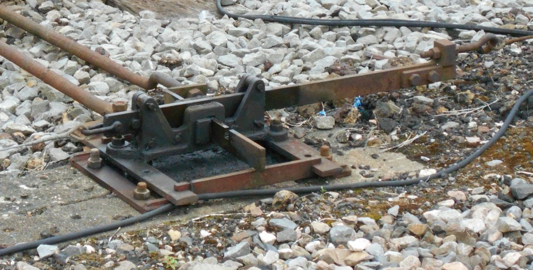 This picture (click for larger image), although of a modern item, illustrates the basic arrangement
that would have existed in a L&BR detector. The signal slide runs from left
to right and the signal wires are attached at each end; at right-angles to this
slide is a single point slide, with the rod that connects it to the switch-blade. Only when the switch-blade is properly closed will the notch seen
in the slide align correctly with the signal slide and allow that slide to move
for the signal to be cleared. There is a similar notch (out of sight) underneath
the signal slide, which allows the point slide to move only when the signal is
in the 'on' position. To the left of the point
slide rod is an additional fixed rod connecting the frame of the detector to
the point to maintain the correct separation distance necessary for accurate
operation of the detector.
This picture (click for larger image), although of a modern item, illustrates the basic arrangement
that would have existed in a L&BR detector. The signal slide runs from left
to right and the signal wires are attached at each end; at right-angles to this
slide is a single point slide, with the rod that connects it to the switch-blade. Only when the switch-blade is properly closed will the notch seen
in the slide align correctly with the signal slide and allow that slide to move
for the signal to be cleared. There is a similar notch (out of sight) underneath
the signal slide, which allows the point slide to move only when the signal is
in the 'on' position. To the left of the point
slide rod is an additional fixed rod connecting the frame of the detector to
the point to maintain the correct separation distance necessary for accurate
operation of the detector.
 Most facing points on the L&BR had a signal for one route only, for
example a Home signal for the left-hand route at the entrance to a
passing-loop, and hence there was only one signal wire slide in the
detector. One exception was the point between the main and bay
platform lines at Lynton, where the Down Home
had arms for both routes, so there were two signal slides;
clearly only one of those would be free to move at any one time, depending
upon the route set at the point. (The other probable exception would have
been the point at Pilton leading from the Down
Loop into the Yard after the addition of the second arm to the Down Home in
1927.) There are few close-up photographs of L&BR detectors, but (apart from the
exceptions mentioned with two signal slides) most appear
to consist simply of one signal slide and one switch blade slide, apparently also with a thick fixed rod connecting the detector
casting to the near rail. Many L&BR detectors seem to be covered by some form
of 'box' enclosure, although in SR days those at Lynton appeared to have been
replaced by an 'open' framework and similar replacements may have occured at
other locations.
Most facing points on the L&BR had a signal for one route only, for
example a Home signal for the left-hand route at the entrance to a
passing-loop, and hence there was only one signal wire slide in the
detector. One exception was the point between the main and bay
platform lines at Lynton, where the Down Home
had arms for both routes, so there were two signal slides;
clearly only one of those would be free to move at any one time, depending
upon the route set at the point. (The other probable exception would have
been the point at Pilton leading from the Down
Loop into the Yard after the addition of the second arm to the Down Home in
1927.) There are few close-up photographs of L&BR detectors, but (apart from the
exceptions mentioned with two signal slides) most appear
to consist simply of one signal slide and one switch blade slide, apparently also with a thick fixed rod connecting the detector
casting to the near rail. Many L&BR detectors seem to be covered by some form
of 'box' enclosure, although in SR days those at Lynton appeared to have been
replaced by an 'open' framework and similar replacements may have occured at
other locations.
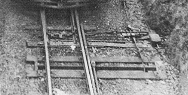
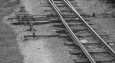
There were a number of places on the L&BR where points were worked on the ground by adjacent hand-levers, rather than by rodding from a signal-box or ground-frame. Such hand-levers were not really a signalling item, but as they are mentioned elsewhere in some RailWest pages about the L&BR it seems appropriate at least to record what little is known about them. These levers were of a pattern described variously as 'turn-over' or 'throw-over', having a large circular weight on the shaft which kept the lever in one position or the other.
 |
 |
 |
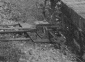
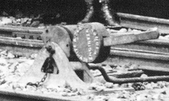
In 1897 the L&BR ordered 11 'lever boxes', of which 8 were destined for 'Barnstaple Yard' (presumably Pilton), 1 for Bratton Fleming and 2 for Lynton. The order was divided into 3 patterns of 'lever box':- Parallel, Square and Underground Box. At Pilton there were to be 2 'underground', 2 'square' and 4 'parallel' examples, whilst those at Bratton Fleming and Lynton were all to be of the 'parallel' type. (Quite what the difference was between the three types, and what governed the choices, is unknown.) The order was placed with James Nuttall, the contractor responsible for building the railway, but no doubt they sourced them from a suitable manufacturer; at least one of the levers at Pilton was cast with the legend 'White & Sons Ltd, Engineers, Widnes' as can be seen in the image on the left above.
The 8 levers for Pilton are presumed to be for the eight sidings which connected into the 'yard loop' line on the Down side. The one for Bratton Fleming would have been destined for the point which connected the two sidings in the goods yard there. It would seem probable that the 2 for Lynton were intended for the engine release crossover between the main platform line and the adjacent run-round loop, which would add weight to the theory that the Lynton release crossover was always worked by hand-levers even in the early days when the signal-box was on the station platform. There would have been another hand-lever in the goods yard at Blackmoor, to control the point for the siding which served the goods shed, but there is no known record of when that was provided and it appears to have escaped the photographic record, so its origin and pattern is unknown.
The left-hand image above was taken in Pilton yard in 1898 and shows that originally the levers were simply a dark colour all over (possibly black?). The middle image above was taken in 1934, also in Pilton yard, but shows a colour scheme known to have been in use there in 1912, where half of each weight was painted in a light colour (white?) and the other half was still a dark colour (black or maybe red?). It may be that the white (?) paint was added to give an indication of the 'lie' of the points and/or to make them more prominent to staff working alongside the track. It is not known if the same colour scheme was applied to any of the levers at other locations.
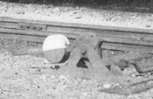
The right-hand image above shows a different pattern of lever photographed at Lynton circa-1935. Although a further hand-lever would have been required when a second siding was added in the goods yard at Lynton circa-1910, it is unclear whether that is the one shown in the photograph - click here for more details.
In simple terms a 'treadle' was an electrical switch located in the track and operated by a passing train. Older types of treadle were fixed usually to the outside of, or underneath, a rail and operated by the deflection of the rail under the weight of the train, so by their nature treadles tend to be elusive items in any photographic record. A treadle would be depressed by a wheel on the first axle of a passing train and continue to be operated by each successive axle until the complete train had passed. The initial depression was usually the important operation, as this activated the relevant circuit and registered the fact that the train had reached the location of the treadle, any subsequent current passing in the circuit would have no further effect. There is no known evidence that any treadles were provided as part of the original L&BR signalling installation, but there is evidence that one existed in SR days on the single-line between Barnstaple Town and Pilton, as described here. Sadly there are no known records regarding its purpose or date of installation and it appears to have escaped the photographic record.
Although telephones might not be regarded as signalling equipment, they were an important means for signalmen to contact other signal-boxes or railway offices. In the days before the use of multi-core cables buried at the side of the track, a traditional feature of older railways was the 'pole route', a line of telegraph poles alongside the track carrying wires for various circuits. (Although telegraph poles were usually wooden, a number of concrete poles were installed in later years.) Photographic evidence suggests that in most places the L&BR pole route carried just two wires, although that number may have increased in the proximity of such places as Pilton. It is presumed that one of those wires was for the single-line ETT instruments, the other being for an 'omnibus' telephone circuit. (Note: early railway electrical systems were designed to use the earth itself as a return path, thereby saving on wire installation and maintenance costs, so a single circuit from A to B would require only one actual 'line' wire.) Given the limited number of known line wires, it is probable that there was a single 'omnibus' telephone circuit on the L&BR, which would have connected all the station booking-offices, as well the manned SBs at Barnstaple Town and Pilton. (It is possible that at larger places such as Pilton there may have been some local telephone circuits, such as between the SB and the yard offices.) There is no evidence that the smaller SBs at the intermediate passing-loops had telephones, as those boxes were normally unmanned and the telephone would have been in the booking-office along with the single-line ETT instruments.
 The only
known view of a L&BR telephone is a poor-quality image inside the booking-office at Chelfham.
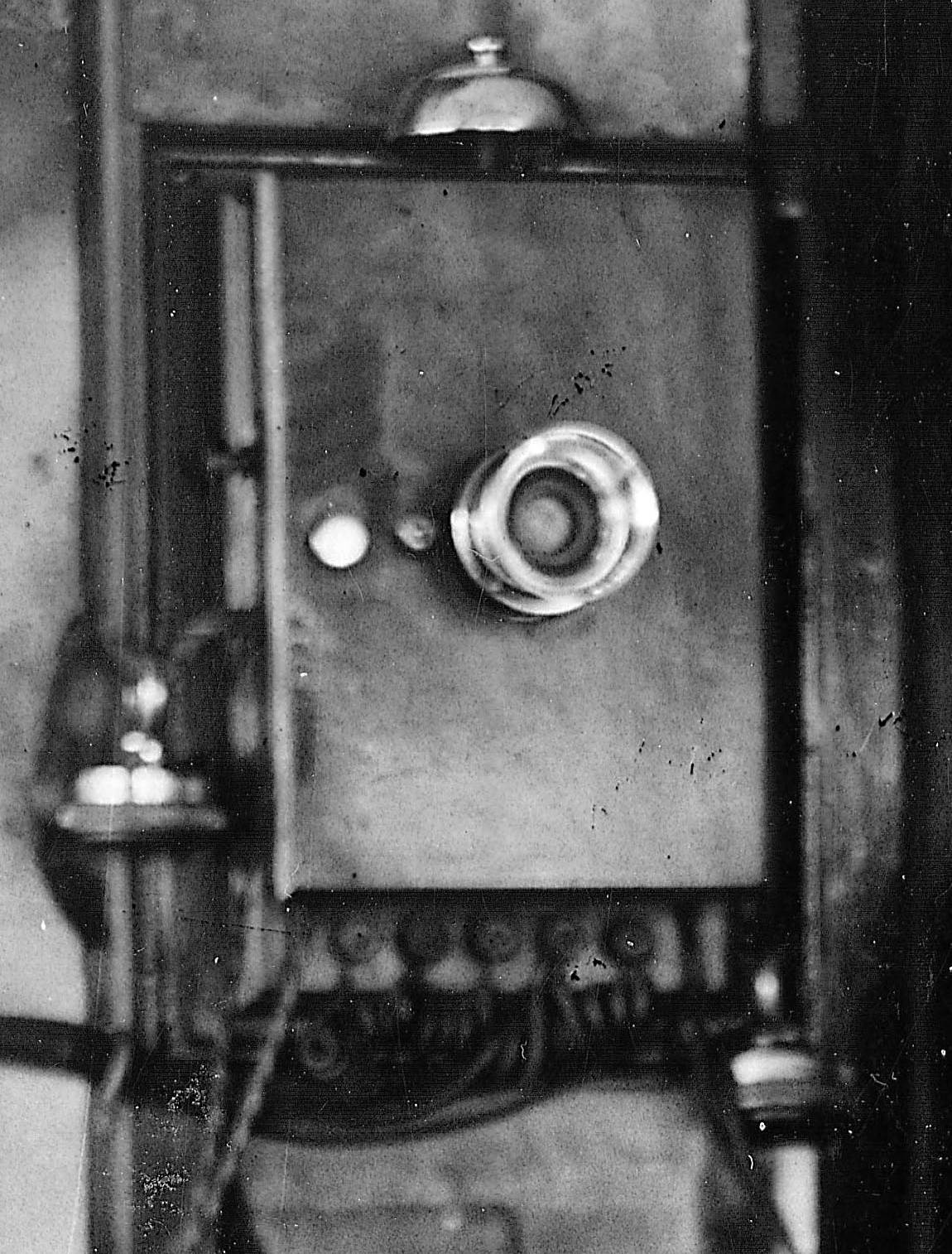
Because of the better picture quality,
the photograph on the right (click for larger image) shows a very
similar instrument in the ex-L&SWR
SB at Barnstaple Town in SR days. This telephone was located above the ETT
instrument for the section to Pilton, so it is assumed that it was
connected to the L&BR omnibus circuit rather than any circuit for the Ilfracombe
line. (It is possible that originally it had been the instrument in the
L&BR SB, relocated after the SR rationalisation in
the 1920s, but would that not have been retained to allow communication
between the signalman and the ground-frame operator?) The telephone was a wooden
box with a hinged front, fixed to the wall. On the top is the bell, in the
middle on the front is a fixed transmitter (mouth-piece), while at the bottom
are the terminals for connecting the various battery and line wires. Hanging on
the 'hook' on the left-hand side is a receiver (ear-piece), connected by a
flexible cable into the case. (There appears to be a second receiver - a common
practice - hanging off the bottom right-hand corner; this would only operate
when the other receiver was 'off-hook'.) Also on the left-hand side of the case,
above the 'hook', was the small push-button which operated the 'ringing'.
The only
known view of a L&BR telephone is a poor-quality image inside the booking-office at Chelfham.
Because of the better picture quality,
the photograph on the right (click for larger image) shows a very
similar instrument in the ex-L&SWR
SB at Barnstaple Town in SR days. This telephone was located above the ETT
instrument for the section to Pilton, so it is assumed that it was
connected to the L&BR omnibus circuit rather than any circuit for the Ilfracombe
line. (It is possible that originally it had been the instrument in the
L&BR SB, relocated after the SR rationalisation in
the 1920s, but would that not have been retained to allow communication
between the signalman and the ground-frame operator?) The telephone was a wooden
box with a hinged front, fixed to the wall. On the top is the bell, in the
middle on the front is a fixed transmitter (mouth-piece), while at the bottom
are the terminals for connecting the various battery and line wires. Hanging on
the 'hook' on the left-hand side is a receiver (ear-piece), connected by a
flexible cable into the case. (There appears to be a second receiver - a common
practice - hanging off the bottom right-hand corner; this would only operate
when the other receiver was 'off-hook'.) Also on the left-hand side of the case,
above the 'hook', was the small push-button which operated the 'ringing'.
All the telephones on an 'omnibus' circuit were wired in parallel, so when someone pressed the call button on his telephone then the bells would ring on all the other telephones on the circuit. Each location would be allocated a 'ring code', comprising a mixture of short and long rings (for example, station A might be '1 Long 2 Short', station B might be '1 Short 1 Long 1 Short' etc), so the caller would ring the code for the destination that he required and the intended recipient would recognise 'his' code and answer the phone. (It was common practice for a 'code list' for the circuit to be displayed near each telephone, but sadly no L&BR list appears to have survived.) It was usually the custom to 'listen before ringing', in case the circuit was in use already for another call. Of course, anyone could 'listen in' to calls on an omnibus circuit, so conversations were not private, but it was useful if you wished to speak to more than one station at the same time.
Note: this is a topic which in fact may not have any relevance to the L&BR, but it would seem worthwhile to provide some brief notes about it here as it has been discussed on occasions elsewhere. It must be stressed that much of the content in this section is a matter of speculation and had been provided here primarily in the hope that it may lead to more specific evidence coming to light in the future.
Arm & Lamp Repeaters. It was important that a signalman could be sure that the arms of semaphore signals under his control were in their correct 'on' (stop/caution) or 'off' (proceed) positions depending upon whether the relevant levers in the signal-box lever-frame were in their 'normal' or 'reverse' positions. Similarly it was important to be sure that the oil lamps used to illuminate the signal aspects at night were indeed alight. Although many signals would be within sight of their controlling signal-box, that was not always the case, so it became a common practice on many UK railways to provide some form of 'Arm' and/or 'Lamp' electric repeater in the signal-box.
Arm repeaters were controlled by a 'circuit controller' (a form of electric switch) attached to the signal arm and the movement of the arm from 'on' to 'off' or vice-versa would cause the indicator to show 'OFF' or 'ON' as appropriate; if the arm failed to move fully from one position to the other than the electric current would be interrupted and the indicator would show 'WRONG'. Lamp repeaters would show simply whether the lamp was alight or not (usually described as the lamp being 'IN' or 'OUT') and these were controlled by a heat-sensitive switch mounted in the top of the lamp casing. If the lamp was alight then the heat from its flame would keep the switch closed and current would flow though the repeater, which would show 'IN', but if the flame went out then the switch would cool down and open to cut the current and the repeater would show 'OUT'.
Repeater Styles. Many different styles of repeater were used by different signalling contractors and railway companies. Some arm repeaters took the form of a miniature representation of a semaphore signal, whereas others used some form of vertical needle moving from side to side between 'ON' or 'OFF' legends. As a very broad generalisation earlier forms of repeaters tended to be in rectangular wood or metal cases, whereas later models were in circular brass cases fixed usually on the front of a shelf or wall (click here for some typical examples). A circular brass pattern with a vertical needle became very common on the Southern Railway (click here to see three examples).
The only known reference to 'repeaters' on the L&BR can be found in National Archives file MT6/876/8, which includes a report for the BoT compiled by W Gamble (apparently an employee of the railway company) providing information in advance of a forthcoming BoT Inspection. This report includes a (proposed) requirement for the Up Distant and Down Distant signals at Bratton Fleming to be 'repeated', which is presumed to mean the provision of electrical indicators in the signal-box; whether the reference was to Arm or Lamp repeaters (or both) is unclear. Given that the two Distant signals existed for less than a year it is not known if such indicators were actually provided at Bratton Fleming nor, if so, of what pattern.
With the exception of the short-lived Distant signals at Bratton Fleming most L&BR signals were visible from their controlling signal-boxes and so there would have been no need for any arm and/or lamp repeaters. However it would seem very likely that at Pilton both the Up and Down Home signals were out of sight of the signalman, so it is possible that arm repeaters (style unknown) may have been provided for them. It should be noted also that at Barnstaple Town after the SR took over the L&BR in 1923 the ex-L&SWR signal-box was provided with 'slots' on the signals already worked from the former L&BR signal-box. Given the location of the L&SWR signal-box, it is clear that the SR signalman would have had no visibility of the L&BR Up Home or Down Advanced Starting signals (and maybe not even the Down Starting), so one may speculate whether arm repeaters were provided for any of those signals, but sadly no relevant records have yet come to light.
During the L&BR's 25 years of independent existence very little of any significance happened on the line that would have required substantial changes to the signalling installations. It was not until a few years into the period of Southern Railway ownership from 1923 onwards that noticeable changes began to occur:-
© CJL Osment 2002-26
Acknowledgements to Michael Bishop and the
Signalling Record Society
for archive information. All images from WCRA collection.
| Interested in
the Lynton & Barnstaple Railway? Then why not join the Lynton & Barnstaple Railway Trust and help to re-build England's premier narrow-gauge line? |
| Introduction | Original Signalling | Economic FPLs | Detectors | Hand-Levers | Treadles | Telephones | Electric Repeaters | Later Changes |
|
© West Country Railway Archives 2002 Page last updated: 11 February 2026 |
URL:
E-Mail: |
||||||


